GEOSYNTHETICS ENGINEERING: IN THEORY AND PRACTICE
|
|
|
- Annabella Poole
- 5 years ago
- Views:
Transcription
1

2 GEOSYNTHETICS ENGINEERING: IN THEORY AND PRACTICE Prof. J. N. Mandal Department of civil engineering, IIT Bombay, Powai, Mumbai , India. Tel


3 Module - 4 LECTURE- 16 Geosynthetics for filtrations, drainages and erosion control systems
4 Recap of previous lecture.. Introduction Mechanism of filtration function Geosynthetics filtration and drainage criteria Geosynthetic drainage applications Subsurface drainage
5 Example: Site conditions: Less critical condition. Stone riprap slope protection with geotextile needed. Step 1: Determine grain size distribution of soil D 60 = 0.18, D 10 = 0.040, D 85 = 0.40, D 15 = 0.05 Step 2: Determine retention criteria C u D C u 8; B = 8/C u = 8/ 4.5 = 1.78 D B D 85 = 1.78 x 0.40 = mm For retention criteria in steady flow condition to be satisfied, A.O.S or O mm
6 Step 3: Determine permeability criteria k soil = (D 10 ) 2 = (0.04) 2 = 1.6 x 10⁻³ cm/sec For less critical and less severe applications, k geotextile 1k soil Therefore, k geotextile 1.6 x 10⁻³ cm/sec Step 4: Determine permittivity criteria For percent in-situ passing mm sieve < 15%, Permittivity (Ψ) 0.5 sec -1 (AASHTO T88)
7 Step 5: Selection of drainage aggregates Range of Coefficient of Permeability (k s ) for materials of different sizes Type Size (mm) Permeability (k s ) (m/sec) Coarse Gravel ~ Medium Gravel ~ Fine Gravel ~ Coarse Sand ~
8 Step 6: Determine clogging criteria For less critical and less severe conditions, O 95 (geotextile) 3 D 15 (soil) for C u > 3 Here, C u = 4.5 > 3 Therefore, O 95 3 D 15 3 x mm Nonwoven geotextile: Porosity 50 % Woven geotextile: Percent open area 5%
9 DESIGNING FOR FILTRATION Geosynthetics can effectively perform the filtration function in different Civil engineering applications like retaining walls, pavement, erosion control, silt fence etc. In a conventional rigid concrete retaining wall, water can pass through the vertical drainage layer to the under drain system or weep holes and consequently, development of hydrostatic pressure behind the retaining wall can be reduced. However, drainage sand layer can become clogged after a passage of time causing the wall to collapse due to generation of high hydrostatic pressure. The problem can be overcome by providing geosynthetics behind reinforced concrete wall or using gabion wall (consisting of wire baskets filled with stones of 100 mm size).
10 Geosynthetic design for filtration: The major criteria for filtration is the cross-plane permeability and apparent opening size of geosyntetic. Step 1: Draw the flow nets behind retaining wall. Determine quantity of flow using the following equation, q k h N N f d q = Flow rate (m 3 / sec/ m), k = Permeability of soil (m/sec) Δh = head lost (m), N f = Number of flow lines, and N d = Number of potential lines

11 Step 2: Determine required permittivity or cross plane permeability When water passes perpendicular or across the plane of the candidate geosynthetics, it is called permittivity or cross plane permeability. Concept of cross plane permeability
12 From Darcy s equation, q = k n. i. A = k n. (h/t g ). A Permittivity (ψ) = k n t g q A. h Ψ = permittivity (sec -1 ) q = flow rate calculated using flow net (m 3 /sec), k n = hydraulic conductivity (Normal to geosynthetic) (m/s), A = area of geosynthetics = W x L (m 2 ), h = head lost (m), and t g = thickness of geosynthetic (m)
13 Slope representation of permittivity
14 Step 3: Determine the ultimate permittivity of geosynthetic (Ψ ult ) from laboratory tests. a) Constant head method Permittivity (ψ) = k n t g q A. h Q = total water collected after time t Hence, flow rate = q = Q/ t A = cross-sectional area of geosynthetic = (W x L) k n = cross-plane permeability of geosynthetic t g = thickness of geosynthetic
15 b) Falling head method K t g n a 2.3 At log 10 h h 0 f a = area of stand pipe (m 2 ) A = area of geosynthetic (m 2 ) t = time change between h 0 and h f (sec) h 0 = head at beginning of the test (m) h f = head at end of the test (m)
16 Step 4: Determine the allowable permittivity of geosynthetic (Ψ allow ) using the following equation in case of flow related problems (Koerner, 1995), ult ψ allow = cum ulative reduction factors ψ The range of recommended reduction factors depends on the type of application (Koerner, 1995) such as, retaining wall, erosion control, pavement, landfill, gravity drainage, and pressure drainage etc
17 Step 5: Determine the factor of safety (FS) F.S. A llow able perm ittivity of candidate geosynthetic R equired perm ittivity of candidate geosynthetic = allow reqd Step 6: If the factor of safety is adequate, the candidate geosynthetics is acceptable, otherwise try a different candidate geosynthetic.
18 Step 7: Determine all parameters such as, Effective diameter of soil, d 10 (mm) Coefficient of uniformity of the soil, C u Coefficient of permeability of the soil (m/ sec) Relative density of soil (DR)%, and d 85 (mm) from the grain size distribution curve of the site specific soil
19 Step 8: Check the required apparent opening size of candidate geosynthetics (AOS or O 95reqd ) to prevent the soil loss based on the soil retention criteria. Four methods can be used for soil retention criteria: Task force 25 (1991) Carroll method, (1983) Giroud method (1982), and Luettich et al. (1992) Carroll method can be used for non-critical cases, whereas Giroud method can be used for critical case.
20 Task force 25 (AASHTO, 1991) a) For particles 50 % passing the No. 200 sieve (0.075 mm), O 95 No 30 sieve (0.60 mm) b) For particles > 50 % passing the No. 200 Sieve, O 95 No. 50 Sieve (0.30 mm)
21 Carroll Method (1983) This method can be used for noncritical cases. O 95 < (2 or 3) d 85 i.e. O 95 < 2.5 d 85 d 85 = particle size at percentage finer of 85%
22 Giroud Method (1982) The required apparent opening size of geotextile varies for different relative densities of soil as reported in the Table. Type of soil Loose granular soil Medium granular soil Dense granular soil Relative density of the soil (D R ) Plasticity Index (PI)< 5 Liner coefficient of uniformity of the soil (C u ) 1 < C u < 3 C u > 3 D R < 50 % O 95 < C u d 50 O 95 <(9 d 50 )/C u D R < 80 % O 95 <1.5C u d 50 O 95 <(13.5 d 50 )/C u D R > 80 % O 95 <2 C u d 50 O 95 <(18 d 50 )/C u
23 Luettich et al. (1992) Soil retention criteria for geotextile filter design under steady-state flow conditions
24 d x = the particle size of which x percent is smaller I D = relative density of the soil PI = plasticity index of the soil DHR =double-hydrometer ratio of the soil O 95 = geotextile opening size C C u c d d d d 30 d d' 100 and d' 0 are the extremities of a straight line drawn through the particle size distribution as directed above and d' 50 is the midpoint of this line.
25 Soil retention criteria for geotextile filter design under dynamic flow conditions. (After Luettich et al., 1992) C u d d 60 10
26 Step 9: Determine the allowable apparent opening size of geosynthetics (O 95 allow ) from the laboratory sieve test. Step 10: Determine the factor of safety of geosynthetic against apparent opening size. F.S. O O 9 5 req d 9 5 a ct Step 11: If the FOS is not adequate (i.e. opening size of the candidate geosynthetic is larger enough and fails to retain soil), try with another candidate geosynthetics. It must satisfy the permittivity and soil retention criteria.
27 Step 12: Clogging criterion (long-term flow compatibility) Gradient ratio test (GRT) should be conducted. Check that gradient ratio 3. In that case, the geosynthetic is free from clogging.
28 Applications: I. Geosynthetics behind retaining walls In a conventional reinforced concrete retaining wall, granular soil is used as vertical drainage layer to allow the water from backfill soil to the under drains or weep holes. Over the passage of time, sand drain may become excessively clogged due to the retained backfill soil. As a result, excessive hydrostatic pressure builds up in the backfill zone causing failure of the structure. A layer of geosynthetic filter, introduced at the back of the retaining wall, will retain the backfill soil and allow only water to filter into the granular drainage layer.
29 Geosynthetic behind retaining wall for filtration

30 A gabion wall is made of galvanized wire baskets filled with stones of size nearly 100 mm or larger stones. It is a flexible wall with its free draining system. It also requires a geosynthetic filter at the back as shown in Figure below. Geosynthetic as filter behind gabion wall
31 Giroud (1988) reported the typical hydraulic gradients: 1) If the drainage is for embankment, road and slope etc, the hydraulic gradient will be less than one. 2) If the drainage is for wall and trenches, the hydraulic gradient will be 1.5.

32 Example: A flexible retaining wall of 4.5 m height is made of gabion which consists of 1 m 1 m 4 m baskets. It rests on a 0.5 m 2 m 4 m mattress as shown below.
33 Properties of silty sand Particle size finer than 85% = d 85 = 0.12mm, Particle size finer than 50% = d 50 = 0.06 mm Effective particle size = d 10 = 0.02 mm Relative density =R D = 85% Coefficient of uniformity = C u = 2.7 Coefficient of permeability of soil (k) = m/sec Candidate Geotextile: (Non woven needle punched) Apparent opening size (A.O.S.) = 0.25 mm Permittivity of geotextile = Ψ = 1.1/sec Cumulative reduction factor (R.F.) = 12 Check suitability of geotextile.
34 Solution: Two stages of design Flow factor of safety Opening size of geotextile, i.e. retention criteria Flow factor of safety Step 1: Calculate actual flow rate using flow net. q k h N N f d q = Flow rate, k soil = m/sec, Δh = 4.5, N f = 4, N d = 5 q m 3 /sec/m
35 Step 2: Required permittivity of geotextile (Ψ reqd ) reqd k t n g q h.a L q = m 3 /sec/m, k n = Coefficient of permeability normal to the geotextile Δh = Hydraulic head = 4.5, t g = Thickness of the geotextile, and A L = Area of geotextile per meter length= (4.5 1) m 2 reqd (4.51) sec
36 Step 3: Allowable permittivity of geotextile Ψ ult = 1.1 /sec (Given) allow ult R.F /sec Step 4: Factor of safety F.S allow Re qd F.S (Ok)
37 Step 5: Geosynthetics opening size, i.e. retention criterion As it is not critical, apply Carroll s criteria O 95 < 2.5 d 85. O 95 = 0.25 mm 2.5 d 85 = = 0.3 mm Hence, O 95 < 2.5 d 85 Therefore, soil retention criterion is satisfied.
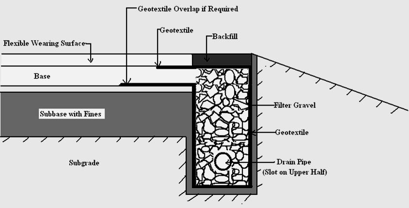
38 II. Geosynthetic filters around under-drains in high way Generally, crushed stones and/or perforated pipes are conventionally used as under-drains for filtration in highways, railways and airfields. However, after a passage of time the under-drain systems become clogged due to seepage of water through native soil to the crushed stones. Therefore, layers of geosynthetics surrounding the stones/ aggregates are to be provided to protect the aggregates from fine soil contamination. Some applications of geosynthetics in under-drains without and with perforated pipe are shown here.


39 Conventional aggregate drain with perforated pipe Geosynthetics around aggregates with perforated pipe Geosynthetic wrapped aggregate without pipe

40 Use of geosynthetics in different pavement under-drains:
41
42
43 Installation procedure of geosynthetics in under drain: Sequential procedure for under drain construction with geosynthetic
44 Step 1: Excavate the sub grade soil to form a required size of trench as shown in Figure (a). Step 2: Place the geosynthetic such as there should not be any void space behind the geosynthetic. Avoid any kind of folding or wrinkling on the geosynthetic as shown in Figure (b). Step 3: Place granular aggregates at the bottom of trench as a bedding layer up to minimum 10 cm height before the placement of perforated pipe or collector pipe (if required) as shown in Figure (c).
45 Step 4: Remaining portion of the trench should be filled up with granular material under proper compaction as shown in Figure (d). Generally, compaction is done by vibratory equipment. The minimum compaction should be 95% standard proctor. Step 5: When compaction is over to the required depth of the trench, overlap the geosynthetic on the top of the granular materials as shown in Figure (e). The minimum overlap should be 30 cm to 60 cm for drain. The overlap helps to protect the drainage aggregate from surface contamination.
46 Step 6: The remaining part (minimum 30 cm) of the trench should immediately be filled up with loosely excavated materials and compacted [Figure (f)]. It is preferable not to expose the geosynthetic to sunlight, dirt or any kind of damage. Geosynthetics will prevent the soil from migrating into the aggregates while allow the water to flow. As transmissivity of open graded stones is adequate, there is no need for a perforated pipe in the drainage system.

47 Example: A geotextile filter is provided around the under-drain in a highway. Design the geotextile filter. Geosynthetics around highway under-drain
48 Size of drain = (350 mm x 550 mm) Δh = 500 mm Soil Properties: Coefficient of curvature, C c = 1.8, Coefficient of uniformity, C u = 4, Particle size finer than 50%, d 50 = 0.03 mm Relative density, R D = 75% Geotextile properties: Apparent opening size, A.O.S. = 0.20 mm q ult = 12 m 3 /day/m Permittivity = Ψ = 1.2/sec Cumulative reduction factor, R.F. = 20
49 Solution: Permittivity criterion Step 1: Calculate required permittivity (Ψ reqd ) reqd k t n g q h.a L reqd / day= /sec q = Maximum flow rate coming from the top aggregates = 12 m 3 /day/m, Δ h = 0.5 m, A L = Area of geotextile per meter length = (0.35 x 1) m 2
50 Step 2: Calculate allowable permittivity of geotextile Given, Ψ ult = 1.2 /sec Ψ allow = (1.2/ R.F.) = 1.2 / 20 = 0.06 / sec Step 3: Factor of safety F.S allow Reqd F.S (Ok)
51 Retention criterion Step 4: Apparent opening size of geotextile According to Luettich et al. (1992), under steady-state flow conditions for R D = 75 % and C u = 4, we can write, O 95 = Apparent opening size < 18 d 50 / C u 18 d 50 / C u = 18 x 0.03/4 = Given, Apparent opening size (A.O.S.) = O 95 = 0.20 Therefore, F.S. = 0.135/ 0.2 = (Not acceptable)
52 The candidate geosynthetic is not acceptable. Soil will not be retained as opening size is too big. So, alternative geosynthetics with tight pore structure is needed. As the permittivity factor is too high, tighter geosynthetics can reduce the factor of safety for permittivity. Then both permittivity and retention criteria will be satisfied. Similarly, we can apply geosynthetics in the following areas: Geosynthetics as silt fences Geosynthetics beneath erosion control structure
53 Please let us hear from you Any question?

54 Prof. J. N. Mandal Department of civil engineering, IIT Bombay, Powai, Mumbai , India. Tel
Application of Geotextiles in Pavement Drainage Systems
 International Journal of Civil Engineering Research. ISSN 2278-3652 Volume 5, Number 4 (2014), pp. 385-390 Research India Publications http://www.ripublication.com/ijcer.htm Application of Geotextiles
Providing proper drainage system
 Environment Friendly and Cost Effective Alternative to Conventional Graded Filters Providing proper drainage system for structures such as earth retaining structures, pavements, water front structures,
GEOSYNTHETICS ENGINEERING: IN THEORY AND PRACTICE
 GEOSYNTHETICS ENGINEERING: IN THEORY AND PRACTICE Prof. J. N. Mandal Department of civil engineering, IIT Bombay, Powai, Mumbai 400076, India. Tel.022-25767328 email: cejnm@civil.iitb.ac.in Module - 9
GEOSYNTHETICS ENGINEERING: IN THEORY AND PRACTICE
 GEOSYNTHETICS ENGINEERING: IN THEORY AND PRACTICE Prof. J. N. Mandal Department of civil engineering, IIT Bombay, Powai, Mumbai 400076, India. Tel.022-25767328 email: cejnm@civil.iitb.ac.in Module-5 LECTURE-
GEOSYNTHETICS ENGINEERING: IN THEORY AND PRACTICE
 GEOSYNTHETICS ENGINEERING: IN THEORY AND PRACTICE Prof. J. N. Mandal Department of civil engineering, IIT Bombay, Powai, Mumbai 400076, India. Tel.022-25767328 email: cejnm@civil.iitb.ac.in Module-5 LECTURE-
SPECIFICATIONS FOR PRECAST MODULAR BLOCK RETAINING WALL SYSTEM (revised 5/8/7)
") Page 1 of 7 STONE STRONG SYSTEMS SPECIFICATIONS FOR PRECAST MODULAR BLOCK RETAINING WALL SYSTEM (revised 5/8/7) PART 1: GENERAL 1.01 Description A. Work includes furnishing and installing precast modular
Page 1 of 7 STONE STRONG SYSTEMS SPECIFICATIONS FOR PRECAST MODULAR BLOCK RETAINING WALL SYSTEM (revised 5/8/7) PART 1: GENERAL 1.01 Description A. Work includes furnishing and installing precast modular
GEOSYNTHETICS ENGINEERING: IN THEORY AND PRACTICE
 GEOSYNTHETICS ENGINEERING: IN THEORY AND PRACTICE Prof. J. N. Mandal Department of civil enineerin, IIT Bombay, Powai, Mumbai 400076, India. Tel.022-25767328 email: cejnm@civil.iitb.ac.in Module - 3 LECTURE-
SPECIFICATIONS FOR PRECAST MODULAR BLOCK RETAINING WALL SYSTEM (revised 9/17/18)
") Page 1 of 8 STONE STRONG SYSTEMS SPECIFICATIONS FOR PRECAST MODULAR BLOCK RETAINING WALL SYSTEM (revised ) PART 1: GENERAL 1.01 Description A. Work includes furnishing and installing precast modular blocks
Page 1 of 8 STONE STRONG SYSTEMS SPECIFICATIONS FOR PRECAST MODULAR BLOCK RETAINING WALL SYSTEM (revised ) PART 1: GENERAL 1.01 Description A. Work includes furnishing and installing precast modular blocks
GEOSYNTHETICS ENGINEERING: IN THEORY AND PRACTICE
 GEOSYNTHETICS ENGINEERING: IN THEORY AND PRACTICE Prof. J. N. Mandal Department of Civil Engineering, IIT Bombay, Powai, Mumbai 400076, India. Tel.022-25767328 email: cejnm@civil.iitb.ac.in Module - 6
Subject Index ASTM D , 28, 57, 63, 67, 83-86, 98, 111, ASTM D , 57
 STP952-EB/JUI. 1987 Subject Index Abrasion resistance, 120, 168-169 Apparent opening size, 7, 21, 29-30, 172-173 defined, 30 versus equivalent opening size, 9-12 Apparent slope height, 96 Approved list,
MagnumStone Specifications Gravity
 MagnumStone Specifications Gravity SPECIFICATION FOR MAGNUMSTONE GRAVITY MECHANICALLY STABILIZED EARTH SYSTEM PART 1: GENERAL.01Description The work consists of supplying and installing all aspects of
Landfill design General principles
 Landfill design General principles Average height of a landfill should be at least 15 m Each section (cell) should accommodate waste to be landfilled during 5 years period Sections/cells should be hydraulically
Michigan State University Construction Standards SEGMENTAL CONCRETE RETAINING WALLS PAGE SECTION SEGMENTAL CONCRETE RETAINING WALLS
 PAGE 323223-1 SECTION 323223 PART 1 - GENERAL 1.1 RELATED DOCUMENTS A. Drawings and general provisions of the Contract, including General and Supplementary Conditions and Division 01 Specification sections,
PRACTICAL COURSE III CLASSIFICATION & COMPACTION. Res. Assist. İREM KALIPCILAR
 PRACTICAL COURSE III CLASSIFICATION & COMPACTION Res. Assist. İREM KALIPCILAR Group index REMINDER GI = (F 200-35)[0.2 + 0.005 (LL-40)]+0.01(F 200-15)(PI-10) FOR GROUP A-2-6 and A-2-7 GI = 0.01(F 200-15)(PI-10)
SAMPLE CONSTRUCTION AND MATERIAL SPECIFICATIONS FOR THE ULTRABLOCK GRAVITY WALL SYSTEM
 SAMPLE CONSTRUCTION AND MATERIAL SPECIFICATIONS FOR THE ULTRABLOCK GRAVITY WALL SYSTEM The following paragraphs provide general guidelines on developing construction and material specifications for specific
Design and Construction Aids in Advanced Geosynthetics Engineering. J. N. Mandal
 Draft copy Design and Construction Aids in Advanced Geosynthetics Engineering J. N. Mandal About this book: This book is the source of current state-of-the-art knowledge and practice which he has acquired
Standards for Soil Erosion and Sediment Control in New Jersey May 2012 STANDARD FOR RIPRAP. Conditions Where Practice Applies
 STANDARD FOR RIPRAP Definition A layer of loose rock, aggregate, bagged concrete, gabions, or concrete revetment blocks placed over an erodible soil surface. Purpose The purpose of riprap is to protect
Civil Engineering Department College of Engineering
 Civil Engineering Department College of Engineering Course: Soil Mechanics (CE 359) Lecturer: Dr. Frederick Owusu-Nimo What is permeability? A measure of how easily a fluid (e.g., water) can pass through
GEOSYNTHETICS ENGINEERING: IN THEORY AND PRACTICE
 GEOSYNTHETICS ENGINEERING: IN THEORY AND PRACTICE Prof. J. N. Mandal Department of civil engineering, IIT Bombay, Powai, Mumbai 400076, India. Tel.022-25767328 email: cejnm@civil.iitb.ac.in Module-5 LECTURE-
SECTION SPECIFICATION FOR STONEBRIDGE RETAINING WALL SYSTEM
 SECTION 32 32 23 SPECIFICATION FOR STONEBRIDGE RETAINING WALL SYSTEM PART 1: GENERAL 1.01 Scope Work includes furnishing all materials, labor, equipment, and supervision to install a Stonebridge segmental
SOIL MECHANICS I ( SEMESTER - 5 )
") SOIL MECHANICS I ( SEMESTER - 5 ) CS/B.TECH (CE)/SEM-5/CE-501/07/(08) 1. Signature of Invigilator 2. Signature of the Officer-in-Charge Reg. No. Roll No. of the Candidate CS/B.TECH (CE)/SEM-5/CE-501/07/(08)
SOIL MECHANICS I ( SEMESTER - 5 ) CS/B.TECH (CE)/SEM-5/CE-501/07/(08) 1. Signature of Invigilator 2. Signature of the Officer-in-Charge Reg. No. Roll No. of the Candidate CS/B.TECH (CE)/SEM-5/CE-501/07/(08)
GEOGRID CONNECTION DETAIL OLYMPIA RADIUS UNIT
 PLACE TWO STANDARD CONNECTORS IN EACH UNIT AS SHOWN (VERTICAL ORIENTATION) INSERT TWO CONNECTORS PER HORIZONTALLY ORIENTED BLOCK; INSERT ONE CONNECTOR PER VERTICALLY ORIENTED BLOCK SHIM BETWEEN BLOCK COURSES
VERTI-BLOCK - DESIGN MANUAL
 Company Information General Information Verti-Block is the latest innovative forming system from Verti-Crete, LLC. Recognized worldwide for outstanding aesthetics and performance, Verti-Crete s proprietary
CYPRESS Stone Geogrid Reinforced Retaining Wall Installation Specification SECTION CONCRETE SEGMENTAL RETAINING WALL PART 1 GENERAL
 CYPRESS Stone Geogrid Reinforced Retaining Wall Installation Specification SECTION 02832- CONCRETE SEGMENTAL RETAINING WALL PART 1 GENERAL 1.01 Description A) The work covered by this section includes
SECTION MECHANICALLY STABILIZED EARTH RETAINING WALLS
 SECTION 13100 MECHANICALLY STABILIZED EARTH RETAINING WALLS PART 1 -- GENERAL 1.01 THE REQUIREMENT A. Includes all labor, material, equipment, testing and submittals required to design and complete construction
SECTION SUBDRAINAGE
 SECTION 33 46 00 SUBDRAINAGE PART 1 GENERAL 1.01 SECTION INCLUDES A. CONTRACTOR shall furnish all labor, tools, and equipment and perform all Work necessary for, or incidental to, the supply and installation
GEOSYNTHETICS ENGINEERING: IN THEORY AND PRACTICE
 GEOSYNTHETICS ENGINEERING: IN THEORY AND PRACTICE Prof. J. N. Mandal Department of civil engineering, IIT Bombay, Powai, Mumbai 400076, India. Tel.022-25767328 email: cejnm@civil.iitb.ac.in Module-5 LECTURE-
STANDARDIZATION IN GEOTECH SECTOR V.K.PATIL
 STANDARDIZATION IN GEOTECH SECTOR V.K.PATIL BOMBAY TEXTILE RESEARCH ASSOCIATION L.B.S.MARG, GHATKOPAR (W),MUMBAI-400086. WEB : btraindia.com e-mail : btra@vsnl.com What are Standards? Standards are published
CHAPTER 8 SEEPAGE CONTROL IN EMBANKMENTS
 CHAPTER 8 SEEPAGE CONTROL IN EMBANKMENTS 8-1. General. All earth and rock-fill dams are subject to seepage through the embankment, foundation, and abutments. Seepage control is necessary to prevent excessive
Verti-Block Design Manual Section 1 - Gravity Wall (Standard)
") Canadian Version Release 2.0 Verti-Block Design Manual Section 1 - Gravity Wall (Standard) Native gravelly soil, edge of excavation Native soil compacted in place as each course is set Geotextile Filter
Canadian Version Release 2.0 Verti-Block Design Manual Section 1 - Gravity Wall (Standard) Native gravelly soil, edge of excavation Native soil compacted in place as each course is set Geotextile Filter
Rethinking Water Management Systems
 Rethinking Water Management Systems Table of Contents Introduction... 1 PIPE-R Reservoir System Installation Procedure... 2 Product Delivery and Assembly... 2 Site Layout and Excavation... 3 Preparation
SPECIFICATIONS FOR DRAINTUBE DRAINAGE GEOCOMPOSITES
 SPECIFICATIONS FOR DRAINTUBE DRAINAGE GEOCOMPOSITES The following sample specification provides guidance for preparing site-specific specifications for using Draintube as a drainage geocomposite. This
NOTES ON CORRUGATED PLASTIC PIPE SUBSOIL DRAIN CONSTRUCTION SPECIFICATION
 TNZ F/5 Notes: 2000 NOTES ON CORRUGATED PLASTIC PIPE SUBSOIL DRAIN CONSTRUCTION SPECIFICATION These notes are for guidance and must not be included in the Contract Documents In general subdivision numbers
Behavior of Geosynthetic-Reinforced Earth
 Behavior of Geosynthetic-Reinforced Earth Presented by Kousik Deb Assistant Professor Department of Civil Engineering IIT Kharagpur Problems for Foundations on Weak Soils Experience excessive settlement
Redi Rock Specification and Installation Manual
 Redi Rock Specification and Installation Manual 1.0 General Scope This Specification covers the Design, Materials and Installation of Redi Rock modular block Retaining and Freestanding Wall systems as
Section 208. SOIL EROSION AND SEDIMENTATION CONTROL
 208.01 Section 208. SOIL EROSION AND SEDIMENTATION CONTROL 208.01. Description. This work consists of installing and maintaining erosion and sedimentation controls to minimize soil erosion and control
WATER AND DRAINAGE. Drainage Around Walls Water Applications Drainage Structures Water and Drainage Q & A
 WATER AND DRAINAGE Drainage Around Walls Water Applications Drainage Structures Water and Drainage Q & A H CONSTRUCTION H-1 W A T E R A N D D R A I N A G E DRAINAGE AROUND WALLS Poor drainage is a leading
MECHANICALLY STABILIZED EARTH (MSE) WALL SYSTEMS
 WALL SYSTEMS") DRAINAGE SOLUTIONS SINCE 1908 MECHANICALLY STABILIZED EARTH (MSE) WALL SYSTEMS PERMANENT AND TEMPORARY ENGINEERED WALL SOLUTIONS ECONOMICAL DURABLE VERSATILE ARMTEC.COM MSE RETAINING WALLS Armtec Mechanically
DRAINAGE SOLUTIONS SINCE 1908 MECHANICALLY STABILIZED EARTH (MSE) WALL SYSTEMS PERMANENT AND TEMPORARY ENGINEERED WALL SOLUTIONS ECONOMICAL DURABLE VERSATILE ARMTEC.COM MSE RETAINING WALLS Armtec Mechanically
SPECIFICATION FOR MAGNUMSTONE GEOGRID REINFORCED Mechanically Stabilized Earth (MSE) SYSTEM
 SYSTEM") MagnumStone Specifications Geogrid Reinforced SPECIFICATION FOR MAGNUMSTONE GEOGRID REINFORCED Mechanically Stabilized Earth (MSE) SYSTEM PART 1: GENERAL 1.01 Description The work consists of supplying
MagnumStone Specifications Geogrid Reinforced SPECIFICATION FOR MAGNUMSTONE GEOGRID REINFORCED Mechanically Stabilized Earth (MSE) SYSTEM PART 1: GENERAL 1.01 Description The work consists of supplying
Design Manual: Gravity Wall. Section 1
 Design Manual: Gravity Wall Section 1 A Design Manual: Gravity Wall General Information Company Information Verti-Block is the latest innovative forming system from Verti-Crete, LLC. Recognized worldwide
ROADWAY DRAINAGE SYSTEM SYSTEM OVERVIEW
 ROADWAY DRAINAGE SYSTEM SYSTEM OVERVIEW RoaDrain Roadway Drainage System: Enhance Pavement Performance with Synthetic Aggregate Water retention within a pavement layer is a primary cause of pavement failure.
ROADWAY DRAINAGE SYSTEM SYSTEM OVERVIEW
 ROADWAY DRAINAGE SYSTEM SYSTEM OVERVIEW RoaDrain Roadway Drainage System: Enhance Pavement Performance with Synthetic Aggregate Water retention within a pavement layer is a primary cause of pavement failure.
Welded Mesh Gabions and Mattresses River Protection Design Guide Anping County Zhuoda Hardware Mesh Co.,Ltd. Wire Mesh Industrial Zone, Anping
 Welded Mesh Gabions and Mattresses River Protection Design Guide Anping County Zhuoda Hardware Mesh Co.,Ltd. Wire Mesh Industrial Zone, Anping County, Hebei, P. R. China. Tel : 0086-318-7752001 7531068
PROPOSED SEGMENTAL RETAINING WALLS ARGONAUT RETAIL VILLAGE - PHASE I PENSACOLA, FLORIDA
 CERTIFICATE AUTHORIZATION: 2 24 ANCHOR WALL ENGINEERING, LLC MATERIAL NOTES. Concrete Retaining Wall Units: "Anchor Diamond Pro Retaining Wall Units" as manufactured by Block USA under license from Anchor
DRIVABLE GRASS GUIDELINE FOR NON PLANTED DRY INFILL INSTALLATIONS
 DRIVABLE GRASS GUIDELINE FOR NON PLANTED DRY INFILL INSTALLATIONS Please read through this instruction completely before beginning your installation. Be sure the proper equipment, and safety precautions
Apparent Coefficient of Friction, f* to be Used in the Design of Reinforced Earth Structures. Technical Bulletin: MSE - 6
 The Reinforced Earth Company 8614 Westwood Center Drive Suite 1100 Vienna, Virginia 22182-2233 Telephone: (703) 821-1175 Telefax: (703) 821-1815 www.reinforcedearth.com Apparent Coefficient of Friction,
15A NCAC 13B.1624 CONSTRUCTION REQUIREMENTS FOR MSWLF FACILITIES (a) This Rule establishes the performance standards and minimum criteria for
 This Rule establishes the performance standards and minimum criteria for") 15A NCAC 13B.1624 CONSTRUCTION REQUIREMENTS FOR MSWLF FACILITIES (a) This Rule establishes the performance standards and minimum criteria for designing and constructing a new MSWLF unit or lateral expansion
15A NCAC 13B.1624 CONSTRUCTION REQUIREMENTS FOR MSWLF FACILITIES (a) This Rule establishes the performance standards and minimum criteria for designing and constructing a new MSWLF unit or lateral expansion
Chapter 6 Sand Filtration Treatment Facilities
 Sand Filtration Treatment Facilities 6.1 Purpose This chapter presents criteria for the design, construction and maintenance of runoff treatment sand filters. Treatment sand filters are used to collect,
Code No: RR Set No. 1
 Code No: RR320101 Set No. 1 III B.Tech Supplimentary Examinations, Aug/Sep 2008 GEOTECHNICAL ENGINEERING (Civil Engineering) Time: 3 hours Max Marks: 80 Answer any FIVE Questions All Questions carry equal
An Experimental Study on Interfacial Properties of Rock Flour and Design of Reinforced Soil Bed
 An Experimental Study on Interfacial Properties of and Design of Reinforced Soil Bed C Ravi Kumar Reddy 1, G Anugna Sai 2, V Ratna Priya 3, C H Hema Venkata Sekhar 4 1 Professor, Civil Engineering Department,
Typical flow net for the flow beneath the dam with heel cutoff wall [Lambe & R.V. Whitman (1979)]
![Typical flow net for the flow beneath the dam with heel cutoff wall [Lambe & R.V. Whitman (1979)]](/thumbs/86/93193451.jpg "Typical flow net for the flow beneath the dam with heel cutoff wall [Lambe & R.V. Whitman (1979)]") Typical flow net for the flow beneath the dam with heel cutoff wall [Lambe & R.V. Whitman (1979)] Typical flow net for the flow beneath the dam with toe cutoff wall [Lambe & R.V. Whitman (1979)] Exit gradient
Typical flow net for the flow beneath the dam with heel cutoff wall [Lambe & R.V. Whitman (1979)] Typical flow net for the flow beneath the dam with toe cutoff wall [Lambe & R.V. Whitman (1979)] Exit gradient
Gravity Wall. A force to be reckoned with... Gravity (SRW) segmental retaining wall systems are structures
 segmental retaining wall systems are structures") A force to be reckoned with... Gravity (SRW) segmental retaining wall systems are structures lower in height that use the FrogStone unit weight combined with gravel core infill to resist earth pressures
A force to be reckoned with... Gravity (SRW) segmental retaining wall systems are structures lower in height that use the FrogStone unit weight combined with gravel core infill to resist earth pressures
COMPARISON BETWEEN HORIZONTAL DRAINAGE USING NATURAL GRANULAR MATERIAL AND USING INTERDRAIN GEOCOMPOSITES
 COMPARISON BETWEEN HORIZONTAL DRAINAGE USING NATURAL GRANULAR MATERIAL AND USING INTERDRAIN GEOCOMPOSITES CONTENTS: 1. INTRODUCTION 2. FINANCIAL COMPARISON 3. COMPARISON OF DRAINAGE CAPACITIES 1. INTRODUCTION
Prof. B V S Viswanadham, Department of Civil Engineering, IIT Bombay
 49 Module 3: Lecture - 11 on Compressibility and Consolidation Contents Stresses in soil from surface loads; Terzaghi s 1-D consolidation theory; Application in different boundary conditions; Ramp loading;
CW 3120 INSTALLATION OF SUBDRAINS TABLE OF CONTENTS
 December 2010 CW 3120 INSTALLATION OF SUBDRAINS TABLE OF CONTENTS 1. DESCRIPTION...1 1.1 General...1 1.3 Referenced Standard Construction Specifications...1 1.4 Referenced Standard Details...1 2. MATERIALS...1
Evaluation of Structural Performance of Pervious Concrete in Construction
 International Journal of Engineering and Technology Volume 2 No. 5, May, 2012 Evaluation of Structural Performance of Pervious Concrete in Construction S.O. Ajamu 1, A.A. Jimoh 2, J.R. Oluremi 1 1 Department
Features Include: Near Vertical Walls Do it Yourself No Concrete Footings Required
 Features Include: Near Vertical Walls Do it Yourself No Concrete Footings Required Tel: Office: +27 (0)11 964 2995 Fax number: +27 (0)86 601 6692 info@dsmmasonry.co.za www.dsmmasonry.co.za Range three
4.8. Subsurface Infiltration
 4.8. Subsurface Infiltration Subsurface infiltration systems are designed to provide temporary below grade storage infiltration of stormwater as it infiltrates into the ground. Dry wells, infiltration
RetainingWalls. Professor of Geotechnical Engineering and Foundations. Faculty of Engineering - Cairo University. By Dr. Ashraf Kamal Hussein
 RetainingWalls By Dr. Ashraf Kamal Hussein Professor of Geotechnical Engineering and Foundations - 2012 1. Introduction Retaining wall: - a structure which retains from failure a soil mass or other materials
4.8. Subsurface Infiltration
 4.8. Subsurface Infiltration Subsurface infiltration systems are designed to provide temporary below grade storage infiltration of storm water as it infiltrates into the ground. Dry wells, infiltration
Filter Tube Barriers (Instream)
") Filter Tube Barriers (Instream) INSTREAM PRACTICES Flow Control No Channel Flow Dry Channels Erosion Control Low Channel Flows Shallow Water Sediment Control High Channel Flows Deep Water Symbol Photo
Filter Tube Barriers (Instream) INSTREAM PRACTICES Flow Control No Channel Flow Dry Channels Erosion Control Low Channel Flows Shallow Water Sediment Control High Channel Flows Deep Water Symbol Photo
GEOSYNTHETICS ENGINEERING: IN THEORY AND PRACTICE
 GEOSYNTHETICS ENGINEERING: IN THEORY AND PRACTICE Prof. J. N. Mandal Department of civil engineering, IIT Bombay, Powai, Mumbai 400076, India. Tel.022-25767328 email: cejnm@civil.iitb.ac.in Module - 9
Design and Installation Guidelines for Retaining Walls. 1 P age. Geo Products, LLC 8615 Golden Spike Lane Houston, TX Phone:
 Design and Installation Guidelines for Retaining Walls 1 P age Geo Products, LLC 8615 Golden Spike Lane Houston, TX 77086 Phone: 281.820.5493 2011 Geo Products, Fax: 281.820.5499 LLC www.geoproducts.org
MEMORANDUM. TO: STUART OLSON DOMINION CONSTRUCTION LTD. DATE: JANUARY 31, 14 ATTENTION: MR. Dave Bauder, Construction Manager KENNY K. C.KO, P.ENG.
 MEMORANDUM Levelton Consultants Ltd. 150-12791 Clarke Place Richmond, BC V6V 2H9 Canada Tel: 604 278-1411 Fax: 604 278-1042 E-Mail: rhillaby@levelton.com Web Site: www.levelton.com TO: STUART OLSON DOMINION
SECTION FOUNDATION DRAINAGE
 SECTION 33 41 13 SPEC WRITER NOTES: Use this section only for NCA projects. Delete text between // // not applicable to project. Edit remaining text to suit project. PART 1 - GENERAL 1.1 SUMMARY A. Section
General Civil Engineering Applications. International Business Department
 GEOSYNTHETICS BR GNRL 0693-07/2016 Kaymat General Civil Engineering Applications International Business Department Tel: +27 31 717 2300 E-mail: exportsjhb@kaytech.co.za WEB: www.kaytech.co.za Geotextiles
DRIVABLE GRASS GUIDELINE FOR DRIVABLE TURF INSTALLATION
 DRIVABLE GRASS GUIDELINE FOR DRIVABLE TURF INSTALLATION Please read through this instruction completely before beginning your installation. Be sure the proper equipment, and safety precautions are in place.
SPECIFICATION FOR CORNERSTONE GEOGRID REINFORCED SEGMENTAL RETAINING WALL SYSTEM
 CornerStone Specifications Geogrid Reinforced SPECIFICATION FOR CORNERSTONE GEOGRID REINFORCED SEGMENTAL RETAINING WALL SYSTEM PART 1: GENERAL 1.01 Description The work consists of supplying and installing
Pavement materials: Soil
 Pavement materials: Soil Lecture Notes in Transportation Systems Engineering Prof. Tom V. Mathew Contents 1 Overview 1 2 Sub grade soil 2 2.1 Desirable properties................................ 2 2.2
APPENDIX 5: CONSTRUCTION CHECKLISTS
 APPENDIX 5: CONSTRUCTION CHECKLISTS This appendix presents the construction checklists for the various retaining wall mitigation strategies: 10.1 Void Fill 10.2 Surface Bond Overlay 10.3 Reinforced Overlay
LAYING IBSTOCK CLAY PAVERS FOR PERMEABLE PAVEMENTS
 PERMEABLE PAVEMENTS (SUDS) This leaflet highlights the basic requirements for laying Ibstock clay pavers to form a permeable pavement. Ibstock clay pavers are intended for domestic use only i.e. patios
R-TANK SPECIFICATIONS
 TECHNICAL STORMWATER MANAGEMENT R-TANK SPECIFICATIONS PART 1 GENERAL 1.01 Related Documents A. Drawings, technical specification and general provisions of the Contract as modified herein apply to this
HUITEX GEOCELL INSTALLATION MANUAL
 Table of Contents 1 Site Preparation 2 Installation for the Retaining Wall 2.1 Base Preparation 2.2 Footing Installation 2.3 Placement of the Drainage System 2.4 Placement of the HUITEX Geocell panels
SPWA Fall Rural Roads Workshop
 SPWA Fall Rural Roads Workshop Gravel Roads Material Analysis, Surfacing and Maintenance Manoj Jogi Saskatchewan Ministry of Highways & Infrastructure Saskatoon October 19, 2017 Basic Objectives of a Road
PE Exam Review - Geotechnical
 PE Exam Review - Geotechnical Resources and Visual Aids Item Page I. Glossary... 11 II. Parameters... 9 III. Equations....11 IV. Tables, Charts & Diagrams... 14 1. Module 1 - Soil Classification... 14
GEOSYNTHETICS ENGINEERING: IN THEORY AND PRACTICE
 GEOSYNTHETICS ENGINEERING: IN THEORY AND PRACTICE Prof. J. N. Mandal Department of Civil Engineering, IIT Bombay, Powai, Mumbai 400076, India. Tel.022-25767328 email: cejnm@civil.iitb.ac.in Module-13 LECTURE-
SPECIAL SPECIFICATION 4653 Polypropylene Pipe
 2004 Specifications CSJ 2158-01-013, Etc. SPECIAL SPECIFICATION 4653 Polypropylene Pipe 1. Description. Furnish and install polypropylene pipe for constructing polypropylene pipe culverts or polypropylene
CHAPTER 4 GEOTECHNICAL SITE CHARACTERIZATION
 CHAPTER 4 GEOTECHNICAL SITE CHARACTERIZATION Chapter Organization 4.1 Introduction... 4-1 4.2 Applicability... 4-1 4.3 Minimimum Requirements... 4-2 4.3.1 Geotechnical Site Characterization Report... 4-3
Characterizing Engineering Properties of Foundry Sands
 Characterizing Engineering Properties of Foundry Sands Craig H. Benson, PhD, PE Recycled Materials Resource Center University of Washington chbenson@u.washington.edu www.recycledmaterials.org Recycled
Simple Design Alternatives to Improve Drainage and Reduce Erosion at Bridge Abutments
 Simple Design Alternatives to Improve Drainage and Reduce Erosion at Bridge Abutments Mohamed M. Mekkawy Iowa State University 405 Town Engineering Building Ames, IA 50011-3232 meks@iastate.edu David J.
BIG 'O' HDPE Tubing CORRUGATED TUBING FOR AGRICULTURAL, RESIDENTIAL AND HIGHWAY DRAINAGE. Proudly owned and operated in Canada. aquaq.
 BIG 'O' HDPE Tubing CORRUGATED TUBING FOR AGRICULTURAL, RESIDENTIAL AND HIGHWAY DRAINAGE aquaq.ca Proudly owned and operated in Canada. BIG 'O' HDPE TUBING The most recognized brand name for HDPE TUBING
Study was conducted in cooperation with the U.S. Department of Transportation, Federal Highway Administration
 Technical Report Documentation Page 1. Report No, 2. Government Accession No. 3. Recipient's Catalog No. 4. Title and Subtitle Performance Evaluation of Longitudinal Pipe Underdrains 5. Report Date October
DRAINAGE DESIGN AND RUTTING PERFORMANACE GUIDELINES FOR PERMEABLE PAVEMENT
 DRAINAGE DESIGN AND RUTTING PERFORMANACE GUIDELINES FOR PERMEABLE PAVEMENT by Su Ling Cao Daryl Poduska Graduate Assistants Dan G. Zollinger Associate Professor Sponsored by The Uni-Group U.S.A. The Department
LARGE TRIAXIAL TESTS ON FABRIC REINFORCED AND CEMENT MODIFIED MARGINAL SOIL
 IGC 2009, Guntur, INDIA LARGE TRIAXIAL TESTS ON FABRIC REINFORCED AND CEMENT MODIFIED MARGINAL SOIL G.V. Praveen Research Scholar, Faculty, S.R. Engg. College, Warangal, India. V. Ramana Murty Assistant
Leachate Management Leachate Control and Collection
 Leachate Management Leachate Control and Collection Leachate Collection Sanitary landfills have leachate collection and removal system above liner At un-lined landfills and dump sites Perimeter Ditch -
Atterberg limits Clay A Clay B. Liquid limit 44 % 55% Plastic limit 29% 35% Natural water content 30% 50%
 CE 6405 SOIL MECHANICS UNIT I INTRODUCTION Part A 1. Distinguish between Residual and Transported soil. 2. Give the relation between γ sat, G, γ w and e 3. A compacted sample of soil with a bulk unit weight
SECTION TRENCHING
 SECTION 31 23 17 TRENCHING PART 1 GENERAL 1.1 SUMMARY A. Section Includes: 1. Excavating trenches for utilities and utility structures. 2. Bedding. 3. Backfilling and compacting to subgrade elevations.
ITEM 750 ROCK FILTER DAMS
 AFTER MARCH 1, 2012 ITEM 750 ROCK FILTER DAMS 750.1 Description. This work shall consist of the installation of temporary erosion protection and sediment control rock filter dams utilized during construction
SECTION PERMEABLE INTERLOCKING CONCRETE UNIT PAVEMENT
 SECTION 32 14 13 19 PERMEABLE INTERLOCKING CONCRETE UNIT PAVEMENT SECTION 32 14 13 19 PERMEABLE INTERLOCKING CONCRETE UNIT PAVEMENT PART 1 - GENERAL 1.1 SUMMARY A. Section Includes: 1. Permeable Articulating
Table 1. Typical Soil Parameters Description Bulk Density, kn/m 3 Liquid Limit, % Plastic limit, % Natural Moisture Content, % Cohesion, kn/m 2 Compre
 CASE STUDY CONSTRUCTION OF HIGH ROAD EMBANKMENT OVER THICK SOFT SILTY CLAY- A CASE STUDY Radhakrishnan R, Geo-Enviro Engineers P Ltd, Chennai, Tamil Nadu, India, 044-24483522, geoenviro2012@gmail.com.
Geocomposite Edge Drain System Design
 TRANSPORTATION RESEARCH RECORD 1329 Geocomposite Edge Drain System Design JAMES B. GODDARD Since their inception and introduction in the early 1980s, geocomposites have received wide acceptance as edge
BIG O HDPE TUBING HDPE CORRUGATED TUBING FOR AGRICULTURAL, RESIDENTIAL AND HIGHWAY DRAINAGE INCREASE CROP YIELDS LOWER PRODUCTION COSTS
 DRAINAGE SOLUTIONS SINCE 1908 BIG O HDPE TUBING HDPE CORRUGATED TUBING FOR AGRICULTURAL, RESIDENTIAL AND HIGHWAY DRAINAGE INCREASE CROP YIELDS LOWER PRODUCTION COSTS PROTECT FOUNDATIONS IMPROVE HIGHWAY
SEGMENTAL BLOCK RETAINING WALLS. Comply with Division 1 - General Provisions and Covenants, as well as the following:
 SEGMENTAL BLOCK RETAINING WALLS PART 1 - GENERAL 1.01 SECTION INCLUDES Segmental Block Retaining Walls 1.02 DESCRIPTION OF WORK Constructing segmental block retaining walls. 1.03 SUBMITTALS Comply with
PROJECT AT THE DENVER
 POROUS ASPHALT DEMONSTRATION PROJECT AT THE DENVER WASTEWATER BUILDING Ken A. MacKenzie, P.E. Manager, Master Planning Program Urban Drainage and Flood Control District 36 th Annual Rocky Mountain Asphalt
Study and Analysis of Permeable Articulated Concrete Blocks Pavement: With Reference to Indian Context
 Study and Analysis of Permeable Articulated Concrete Blocks Pavement: With Reference to Indian Context Shrikant Charhate, Gayatri Deshpande Abstract Permeable pavements have significant benefits like managing
Presented by: Civil Engineering Academy
 Presented by: Civil Engineering Academy Soil Classification Presented by: Civil Engineering Academy Is an aggregate of loose mineral and organic particles. Exhibits strong and permanent cohesive forces
PRODUCT SPECIFICATION CSI FORMAT Earth Retention System April 2009
 PRODUCT SPECIFICATION CSI FORMAT Earth Retention System April 2009 Cell-Tek Geosynthetics LLC 2431 Crofton Lane, Suite 9 Crofton, MD 21114 USA Toll Free (888) 851-0051 Phone (410) 721-4844 Fax (410) 721-3844
SEPA Environmental Checklist Mercer Island Center for the Arts. Attachment F Geotechnical Supplemental Memo
 SEPA Environmental Checklist Mercer Island Center for the Arts Attachment F Geotechnical Supplemental Memo January 2017 MEMORANDUM DATE: May 6, 2015 TO: FROM: RE: CC: Katie Oman, Mercer Island Center for
Geotechnical Investigation Long Timber Brewing Building Highway 99 and Kelly Street Monroe, Oregon TABLE OF CONTENTS
 Highway 99 and Kelly Street TABLE OF CONTENTS PROJECT INFORMATION... 1 FIELD EXPLORATION... 1 SITE CONDITIONS... 2 Surface Conditions:... 2 Subsurface Conditions:... 2 FILL.... 2 Topsoil.... 2 Clay Alluvium....