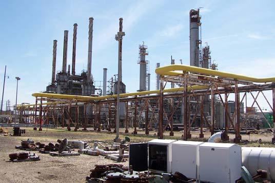
SYNTHETIC NATURAL GAS PLANT. Philadelphia, PA
|
|
|
- Christopher Owen
- 5 years ago
- Views:
Transcription

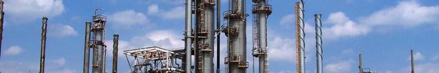
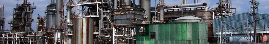
1 SYNTHETIC NATURAL GAS PLANT Philadelphia, PA
2 SYNTHETIC NATURAL GAS PLANT The SNG facility was constructed in 1977 but has seen very little operational activity. The SNG Facility employs the British Gas hydro gasification process to convert naphtha feedstock into SNG at a design rate of 60,000 decatherms per day, and was constructed by Foster Wheeler Energy Corporation. The principle areas of the plant that are offered for sale are as follows: Hydrogen Plant: Produces 5.9 MMSCFD of 99+% of Hydrogen using British Hydro-Gasification Desulphurization Plant: Treats up to 117,500 lbs/hr of 2000 ppm Sulfur to a Sulfur Content Reduced to 5ppm Deionization Plant: Treats 350 GPM Complete with Cation Beds, Anion Beds, Deionization Beds, Carbon Vessels, Pumps & Regeneration System. Philadelphia, PA
 reactor and the second (hydro gasification) reactor.")
3 Hydrogen Plant: Catalytic Rich Gas: Section 200 The CRG process employs the British Gas hydro gasification concept. Full capacity standby reactors are available for the first stage (CRG) reactor and the second (hydro gasification) reactor. Supplemental equipment is available for shut down and start up operations and for catalyst reductions. Hydrogen is produced in the CRG section by combining rich gas or natural gas with superheated steam over nickel catalyst beds in a hydrogen reformer which has a capacity of 5.9 MMSCFD of hydrogen. A Benfield hot potassium carbonate process accomplishes CO2 removal. A PSA purification skid is available for this H2 plant that elevates H2 purity to 99.9% or higher, if desired.
4 Hydrogen Plant: Catalytic Rich Gas: Section 200 Reactors: Reactor Function Size Design Temp Design PSI Normal Temp Normal PSI R-201 Sulfur Hydrogenator 8'ID x 62'3" R-202 Sulfur Absorber 7'6"ID x 32'3" R-204A 1st Stage Rich Gas Reactor 7'ID x 11'6" R-204B Spare 7'ID x 11'6" R-205A 2nd Stage Gas Rich Reactor 10'ID x 9'6" R-205B Spare 10'ID x 9'6" R-206 R-207 R-208 R-209 3rd Stage Rich Gas Reactor Recycle Gas Converter Recycle Gas Methanator Pipe Line Gas Sulfur Absorber 8'ID x 7'6" '5"ID x 17'4" '6"ID x 7' 'ID x 10'2" R-210 Carbon Drum 3'6"ID x 10'6" Vessels


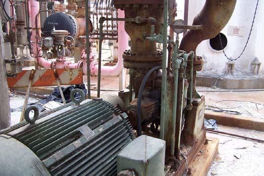
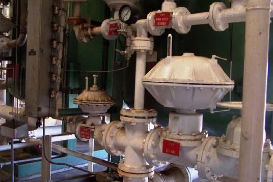
5 Hydrogen Plant: Catalytic Rich Gas: Section 200 R-201: Sulphur Hydrogenator R-205A: 2 nd Stage Gas Rich Reactor R-202: Sulphur Absorber Vessels R-207: Recycle Gas Converter
6 Hydrogen Plant: Catalytic Rich Gas: Section 200 Towers: Tower Function Size T-201 T-202 Rich Gas CO2 Absorber Recycle Gas CO2 Absorber Design Temp Design PSI Normal Temp Normal PSI 10'/7' x 114' '/3' x 110'6" T-203 Carbonate Regenerator 12'6"ID x 141'6" Vessels


7 Hydrogen Plant: Catalytic Rich Gas: Section 200 T-201: Rich Gas CO 2 Absorber T-203: Carbonate Regenerator T-202: Recycle Gas CO 2 Absorber Vessels
8 Hydrogen Plant: Catalytic Rich Gas: Section 200 Drums: Tank Function Design Temp Vessels Desig n PSI Normal Temp Normal PSI D-201 Process Steam Drum D-202 3rd Stage Reactor Drum D-203 Rich Gas Absorber Feed KO Drum D-204 Re-boiler KO Drum D-205 Product Gas KO Drum D-206 Reformer Steam Drum D-207 Recycle CO Converter Eff DO Drum D-208 Recycle Absorber Feed KO Drum D-209 Recycle Gas KO Drum D-211 Regenerator Overhead DO Drum D-212 Startup Cooler KO Drum D-213 Feed Return DO Drum D-214 Carbonate Flash Drum D-215 2nd Stage KO Drum D-216 Recycle Absorber Overhead KO Drum D-217 Pipeline Gas KO Drum


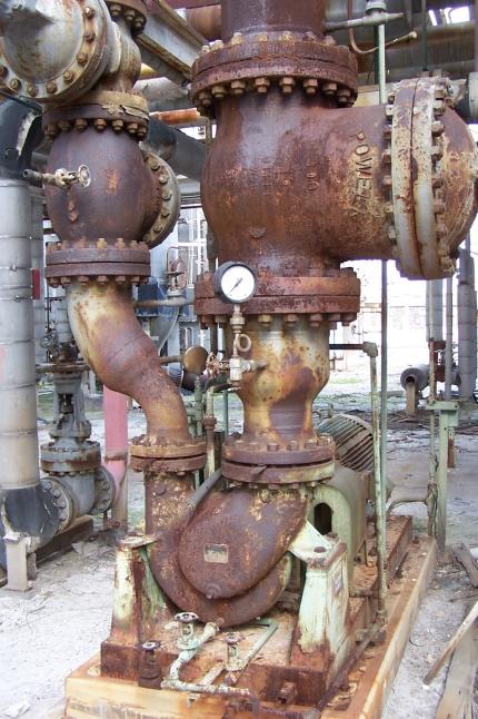
9 Hydrogen Plant: Catalytic Rich Gas: Section 200 D-202: 3 rd Stage Reactor Drum D-205: Product Gas KO Drum D-203: Rich Gas Absorber Feed KO Drum Vessels


10 Hydrogen Plant: Catalytic Rich Gas: Section 200 D-204: Re-boiler KO Drum D-211: Regenerator Overhead DO Drum D-205: Product Gas KO Drum Vessels
11 Hydrogen Plant: Catalytic Rich Gas: Section 200 Shell/Tube Exchangers: Tank Function Shell Fluid Shell Temp F Shell Pressure Tube Fluid Tube Temp F Tube Pressure E-201 1st Stage Waste Heat Exchanger BFW/Stm 460/ /520 Syn Gas 1018/ /415 E-202 2nd Stage Waste Heat Exchanger BFW/Stm 460/ /520 Syn Gas 935/ /370 E-203 Rich Gas LP Steam Generator BFW/Stm 298/298 50/50 Rich Gas 535/ /313 E-204 3rd Stage Feed Pre Heat Exchanger Rich Gas 284/ /303 Rich Gas 682/ / E-205 Carbonate Re-boiler Carb.Sol. 236/236 8/8 Rich Gas 328/ /308 E-206 3rd Stage Waste Heat Exchanger BFW/Stm 460/ /520 Reac.Eff 686/ /288 E-207 3rd Stage Feed Water Exchanger BFW 228/ /701 Rich Gas 500/ /284 E-210 Reformer Gas Waste Heat Exchanger BFW/Stm 460/ /645 Ref. Gas 1382/ /325 E-211 Recycle Gas LP Stm Generator BFW/Stm 298/298 50/50 Conv. Gas 700/ /258 E212 E-213* Treated Water Pre Heater Recycle Meth. FIP Exchanger Treated Water Scrubbed Rec. Gas 60/ /130 Conv. Gas 360/ / / /274 E-214 Recycle Meth. Startup Heater Nitrogen 750/ /195 Meth. Rec. Gas Scrubbed Gas 700/ / / /269 Exchangers


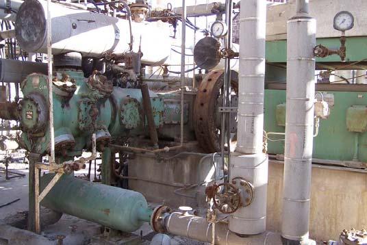
12 Hydrogen Plant: Catalytic Rich Gas: Section 200 E-202: 2 nd Stage Waste Heat Exchanger E-205: Carbonate Re-boiler E-210: Reformer Gas Waste Heat Exchanger E-211: Recycle Gas LP Steam Generator Exchangers
13 Hydrogen Plant: Catalytic Rich Gas: Section 200 Air Cooled Exchangers: Air Side Design Tank Function Temp In Temp Out Fluid Tube Temp F Tube Pressure E-208 Rich Gas Absorber feed Cooler Rich Gas 282/ /278 E-209 Product Gas Cooler Prod. Gas 156/ /163 E-215 Recycle Gas Cooler Recycle Gas 369/ /254 E-216 Regenerator Overhead Condenser CO2 + Steam 242/159 5/1 E-220 Startup Cooler Nitrogen 932/ /240 E-220 Startup Cooler H2+CH4+Steam 752/ /405 E-221 Feed Return Condenser Nap+Recy.Gas 752/ /275 E-221 Feed Return Condenser Pipeline Gas 752/ /395 E-222 Carbonate Solution Cooler Carb. Solution 222/ /395 E-223 Recycle Gas Trim Cooler Converter Gas 360/ /284 E-224 Pipeline Gas Compressor After Cooler Tube Normal (Inlet/Outlet) Nat. Gas 370/ /395 Exchangers


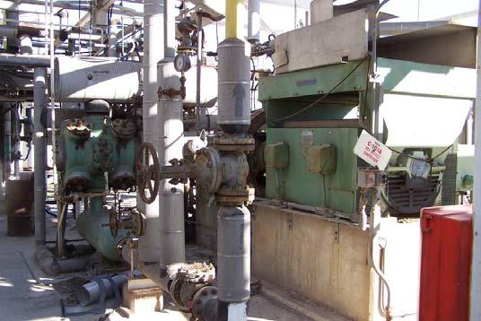
14 Hydrogen Plant: Catalytic Rich Gas: Section 200 E-209: Product Gas Cooler E-220: Start-up Cooler E-222: Carbonate Solution Center E-224: Pipeline Gas Compressor Air Cooler Exchangers
15 Hydrogen Plant: Catalytic Rich Gas: Section 200 Pumps: Pump Function Normal GPM Desig n GPM Pumping Temp Suction Pressure Discharge Pressure Driver Motor HP P-201A Carb. Circ. Pump SF P-201B Spare SF P-203A Regenerator Reflux SF P-203B Spare SF P-206 Carbonate Transfer SF P-207 Carbonate Sump Pump SF Pumps


16 Hydrogen Plant: Catalytic Rich Gas: Section 200 P-201A: Carbonate Circulation Pump P-201B: Spare P-203A: Regenerator Reflux Pumps P-203B: Spare
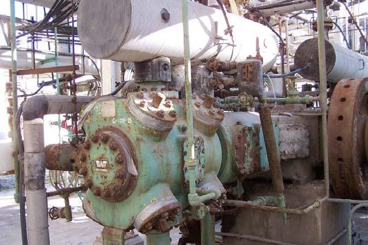
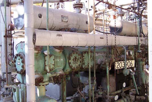
17 Hydrogen Plant: Catalytic Rich Gas: Section 200 Compressors: Tank Function Capacity # Hr Normal Capacity # HR Design Temp Sucti on Temp Discharge Pressur e Suction Pressure Discharg e Driver Motor HP C-201A C-201B Recycle Hydrogen Compressor Spare 1443 # HR 1443 # HR C-202 Startup Compressor C-203A C-203B C-204 Methane Recirc. Compressor Methane Recirc. Compressor Pipeline Gas Compressor # HR 1676 # HR 23,790 # HR 21,300 # HR 21,300 # HR 2675 # HR SF SF SF SF SF Compressors


18 Hydrogen Plant: Catalytic Rich Gas: Section 200 C-202: Start-up Compressor C-203A: Methane Re-circulation Compressor C-204: Pipeline Gas Compressor Compressors

19 Naphtha Hydrodesulphurization Plant Section 100 Vessels: This plant provides a water wash system to remove possible salt contaminants from raw naphtha feedstock. A deaerator is also present in this section to strip dissolved oxygen from the naphtha feedstock. The HDS section will treat up to 117,500 lbs/hr of heavy naphtha of 2000 ppm sulfur to a sulfur content reduced to 5 ppm.
20 Naphtha Hydrodesulphurization Plant: Section 100 Vessels: Vessels: Tank Function Size D-101 Separator D-102 Naphtha Stripper Overhead Drum 7' ID x 22.5' Boot 5' ID x 16.5' Boot Design Temp Design PSI Normal Temp Normal PSI 200 F F F F 90 D-103 Water Wash Drum 6.5' ID x 26' 200 F F 25 D-104 Sour Water Receiver 5' ID x 15' 510 F F 50 D-105 R-101 Compressor Suction Drum Desulphurization Reactor 3' ID x 6' 160 F F 375 7' ID x 22.5' 200 F F 375 T-101 Tower 8' ID x 38'7.5"" 150F 93 NA NA T-102 Tower 7'6"ID x 85'1.5" 515F 146 NA NA Vessels


21 Naphtha Hydrodesulphurization Plant: Section 100 Vessels Vessels: D-101: Separator D-102: Naphtha Stripper D-103: Water Wash Drum


22 Naphtha Hydrodesulphurization Plant: Section 100 Vessels Vessels: D-104: Sour Water Receiver
23 Naphtha Hydrodesulphurization Plant: Section 100 Shell/Tube Exchangers: Tank Function Shell Fluid Shell Temp F Shell Pressure Tube Fluid Tube Temp F Tube Pressure E-101A E-101B E-101C E-101D E-103A/B E-105 Reactor Effluent Feed Exchanger Reactor Effluent Feed Exchanger Reactor Effluent Feed Exchanger Reactor Effluent Feed Exchanger Naptha Stripper Bottoms Feed Exchanger Naptha Feed Preheater H.C.* 503/ H.C.* 750/ H.C.* 400/ H.C.* 612/ H.C.* 255/ H.C.* 508/ H.C.* 70/ H.C.* 404/ H.C.* 110/ H.C.* 439/ Steam 330/ H.C.* 5/70 80 Exchangers


24 Naphtha Hydrodesulphurization Plant: Section 100 Exchangers Vessels: E-101A: Reactor Effluent Feed Exchanger E-101B: Reactor Effluent Feed Exchanger E-103A/B: Naphtha Stripper Bottom Feed Exchanger E-105: Naphtha Feed Pre-heater
25 Naphtha Hydrodesulphurization Plant: Section 100 Vessels: Air Cooled Exchangers: Tank Function Temp In Temp Out Fluid E-102 E-104 E-106 Reactor Effluent Cooler Naphtha Striper Overhead Condenser Desulphfurized Naphtha Cooler Tube Temp F Tube Pressure H.C.* 275/ H.C.* 144/ H.C.* 241/ Exchangers


26 Naphtha Hydrodesulphurization Plant: Section 100 Exchangers Vessels: E-102: Reactor Effluent Cooler E-104: Naphtha Stripper Overhead Condenser E-106: Desulphurized Naphtha Cooler
27 Naphtha Hydrodesulphurization Plant: Section 100 Pumps Vessels: Pumps: Tank P-101A/B Function Naphtha De-aerator GPM Norm al Design GPM Pumping Temp Suction Pressure Discharge Pressure Driver Motor HP P-102A/B Reactor Stripper P-103A/B P-104A/B P-105 P106A Naphtha Stripper Reflux Pump Naphtha Stripper Bottoms Pump Water Circulation Pump Naphtha Stripper Re-boiler Pump '


28 Naphtha Hydrodesulphurization Plant: Section 100 Pumps Vessels: P-101A/B: Naphtha De-aerator P-103A/B:Naphtha Stripper Reflux Pump P-104A:Naphtha Stripper Bottoms Pump P-104B:Naphtha Stripper Bottoms Pump
29 Naphtha Hydrodesulphurization Plant: Section 100 Pumps P106A: Naphtha Stripper Re-boiler Pump Vessels:
30 Naphtha Hydrodesulphurization Plant: Section 100 Compressors & Mixers Vessels: Compressors: Tank C-101A/B Function HDS Recycle Compressor Capacity ACFM Capacity Lb/Min Temp Suction Temp Discharge Pressure Suction Pressure Discharge Driver Motor HP Safety Factor Mixers: Mixer Water Flow Naptha Flow Pressure Drop (Normal) Operating Pressure Operating Temp M GPM Max 406 GPM Max 14 PSI 75 Psig 100F
31 Naphtha Hydrodesulphurization Plant: Section 100 Compressors & Mixers Vessels: C-101A: HDS Recycle Compressor C-101B: HDS Recycle Compressor

32 Stretford Sulphur Recovery The bulk of the sulfur in the plant naphtha feed is removed in the hydrodesulphurization (HDS) unit, the sweet naphtha going to the SNG unit and the sulfur leaving the HDS unit as H2S in the sour gas purge. The sour gas, composed of mainly light hydrocarbons, is burnt in the plant fuel system. In order to reduce pollution of the atmosphere by combustion products to an absolute minimum, the H2S is removed from the sour gas before combustion, by the Stretford Process. The Stretford Process was developed by the North Western Gas Board, now part of the British Gas Corporation, who license the process. The Stretford Process for H2S removal is by continuous liquid washing using an adequate alkaline solution containing dyestuff intermediates. The H2S+O is converted to elemental sulfur, which is separated from the solution, washed to remove the solution from the sulfur cake, and stored ready for disposal. The Stretford Unit that we are offering is designed to treat lb. mol/hr of sour gas containing up to 7.34 lb. mols of H2S and to reduce the H2S content of the sweet gas to less than 1 vppm. Alternatively, the unit can treat lb. mols/hr of sour gas containing up to 1.84 lb. mols H2S. Section 150
33 Stretford Sulphur Recovery: Section 150 Reactor: Reactor Function Size Design Temp Design PSI Normal Temp Normal PSI R-151 Oxidizer 18' x 21' 140F Static Head 110F Atmosphere Tower: Tower Function Size Design Temp Design PSI Normal Temp Normal PSI T-151 H2S Absorber 10' x 4'6" x 90'6" 140F 75F 110F 40 Tanks: Tank Function Size Design Temp Design PSI Normal Temp Normal PSI TK-151 Pumping Tank 14'6" x 15' 140 Static Head 110F Atmosphere TK-152 Slurry Tank 12' x 12' 140 Static Head 110F Atmosphere TK-153 Decanter Tank 10'9" x 7' 140 Static Head 110F Atmosphere TK-154 Filtrate Tank 5' x 6' 140 Static Head 110 F Atmosphere TK-155 Reagent Tank 5' x 6' 140 Static Head 110 F Atmosphere TK-156 HC Flash Tank 8' x 15' F 2 PSIG Vessels


34 Stretford Sulphur Recovery: Section 150 TK-153: Decanter Tank TK-156: HC Flash Tank T-151: H2S Absorber Vessels


35 Stretford Sulphur Recovery: Section 150 P-151A/B: Solution Circulation Pumps P-152A: Slurry Feed Pump P-153A: Re-slurry Pump P-154: Filtrate Pump Pumps


36 Stretford Sulphur Recovery: Section 150 P-151A/B: Oxidizing Air Blowers Blowers

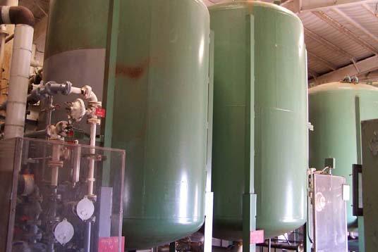
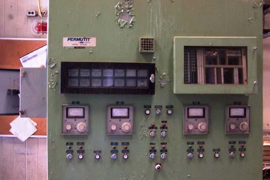
37 Deionization Plant 350GPM 2 Deionization beds (2) Vessels each 2 an-ion beds negative ion removal 2 cat-ion beds positive ions removal 2 Carbon Vessels (hydrocarbon removal carbon absorption units) 4 pumps Regeneration system- strips an-ions and cations off the resins designed for this unit Support facilities include drums, tanks, pumps, compressors, blowers, de-aerator, boilers, Electrical systems and a full demineralization plant/water treatment package. Section 300
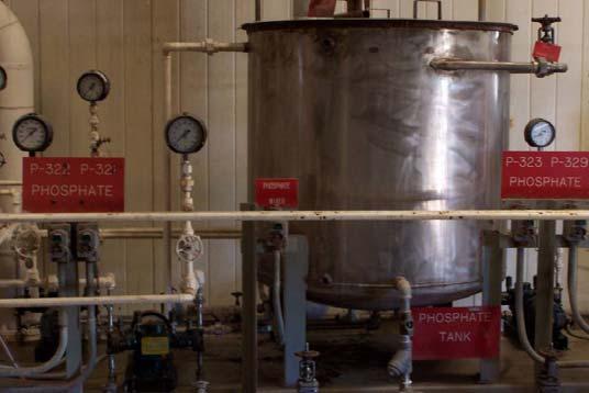
38 Deionization Plant Tanks: Tank Function Capacity (gallons) TK-307 Treated Water 67,680 TK-308 Neut. Tank 44,616 TK-310 Cooling Water Surge Tank 8,550 Size 24' x 24' 15' x 33' 9" 9' x 18' Design Temp Design PSI Normal Temp Normal PSI 210 Atmosphere 160 Atmosphere 150 Atmosphere 120 Atmosphere 170 Atmosphere 120 Atmosphere Drums: Tank Function Design Temp Design PSI Normal Temp Normal PSI D-301 Air Receiver D-302 Caustic Stage Drum Atmosphere D-303 Acid Stage Drum Atmosphere D-307 Fuel Gas KO Drum D-308 Blow down Drum (Stm) Section 300


 TK-308:")
39 Deionization Plant: Section 300 TK-307: Treated Water D-307: Fuel Gas KO Drum D-308: Blow Down Drum (Stm) TK-308: Neutralizing Tank Vessels
40 Deionization Plant: Section 300 Pumps: Pump Function GPM Normal Desig n GPM Pumps Pumping Temp Suction Pressure Discharge Pressure Driver Motor HP P-301A Treated Water Pump Max P-301B Spare Max P-309A Cooling Water Pump P-309B Spare P-311A Naptha Fuel Pump / P-311B Spare / P-319A BFW Pump P-319B BFW Pump P-320A* Hydrazine Pump P-320B* Spare P-321* P-322* Stm Gen Phosphate Pump Pro. Stm. Drum Phosphate Pump P-323* Spare P-329 Phos. to Proc. Stm. Drums


41 Deionization Plant: Section 300 P-309A: Cooling Water Pump P-311A: Naphtha Fuel Pump P-319A: BFW Pump P-319B: BFW Pump Pumps
42 Deionization Plant: Section 300 Compressors & Blowers: Tank Function Capacity ACFM Capacity Lb/Min Temp Suctio n Temp Discharge Pressure Suction Pressure Discharge Driver Motor HP C-301A/B Instrument/Plant Compressor & Spare AMB B-301A/B Forced Draft Fan AMB AMB ATM 13" WC 40 B-302A/B Atomizing Air Blower AMB AMB ATM Compressors/Blowers


43 Deionization Plant: Section 300 DH-301: De-Aerator De-Aerator
44 Deionization Plant: Section 300 Water Treatment Package: The water treatment package consists of carbon purifier, cation, anion, and mixed bed treatment. The equipment is capable of delivering 255,300 gallons per 24 hours at a maximum effluent flow rate of 354 gpm. See chart below for water effluent properties. Test Result Alkalinity 1 ng /L Total Hardness nil Sulfate nil Chloride nil Silica 0.05 ng /L Total Dissolved Solids 1ng/L H 2 O Treatment
45 Deionization Plant: Section 300 H 2 O Treatment

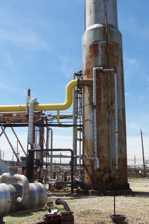
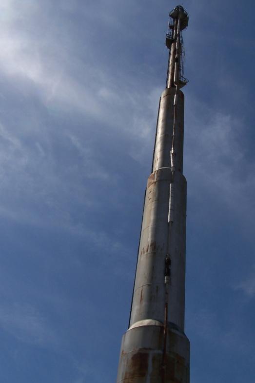
46 Flare Towers A-306


47
2.0 HYDROGEN GENERATION UNIT 2.1 INTRODUCTION
 2.0 HYDROGEN GENERATION UNIT 2.1 INTRODUCTION 2.1.1 PURPOSE The objective of the unit is to produce hydrogen by steam reforming of full range naphtha i.e. C 5-140 O C SR naphtha & coker naphtha to meet
HYDROGEN UNIT CHAPTER-1 INTRODUCTION. The process for hydrogen generation involves the following four major steps.
 CHAPTER-1 INTRODUCTION 1.1 GENERAL The Panipat Refinery Hydrogen Unit is designed to produce 38,000 MTPA of high purity (99.99%) hydrogen gas based on 8,000 hours on-stream operation to cater to the OHCU/DHDS/CCR
4.0 HYDROGEN GENERATION UNIT (PREP) 4.1 INTRODUCTION
 4.1 INTRODUCTION") 4.0 HYDROGEN GENERATION UNIT (PREP) 4.1 INTRODUCTION 4.1.1 PURPOSE The objective of the unit is to produce hydrogen by steam reforming of full range naphtha i.e. C 5-140 O C SR naphtha & coker naphtha
4.0 HYDROGEN GENERATION UNIT (PREP) 4.1 INTRODUCTION 4.1.1 PURPOSE The objective of the unit is to produce hydrogen by steam reforming of full range naphtha i.e. C 5-140 O C SR naphtha & coker naphtha
Item Hydrogen Gas Plant
 Item 6530. Hydrogen Gas Plant Hydro-Chem Hydrogen Generating Plant 90,000 scfh @ 200 psig. Purity 99.99% Hydrogen generating plant engineered by Hydro-Chem built in 1980. Design capacity is 90,000 scfh
Methanol Production by Gasification of Heavy Residues
 Methanol Production by Gasification of Heavy Residues by C. A. A. Higman Presented at the IChemE Conference "Gasification: An Alternative to Natural Gas" London, 22-23 23 November, 1995 Methanol Production
1. Process Description:
 1. Process Description: The coal is converted to Raw Syngas in the Gasification Section. The Raw Syngas produced out of the Gasifier would be shifted (water gas shift) to adjust required H2/CO ratio and
DIESEL HYDRODESULPHURISATION UNIT CHAPTER-9 CATALYST AND REGENERATION
 CHAPTER-9 CATALYST AND REGENERATION 9.1 MANUFACTURER: HR 945 and HR-348 are manufactured by PROCATALYSE : In their facilities located at Salindres 30340 France. PROCATALYSE Head Office Address : 212/216
Control Valve Sourcebook Chemical Process Overview
 Control Valve Sourcebook Chemical Process Overview Ammonia Production Topic Page I Purification of Feedstock............... II Reforming........................ III Shift Conversion....................
Taravosh Jam Design & Engineering Co.
 Taravosh Jam Design & Engineering Co. Taravosh Jam co. as an Iranian EPC contractor supplies following refinery equipment and facilities based on the know-how and to international standards. 1- The Main
COMPETITIVENESS OF GASIFICATION AT THE BULWER ISLAND, AUSTRALIA REFINERY
 COMPETITIVENESS OF GASIFICATION AT THE BULWER ISLAND, AUSTRALIA REFINERY 1999 Gasification Technologies Conference San Francisco, California October 17-20, 1999 Ram Ramprasad and Tarun Vakil, BOC Process
HYDROGEN GENERATION FOR MODERN REFINERIES
 HYDROGEN GENERATION FOR MODERN REFINERIES Luigi Bressan, Guido Collodi, Fabio Ruggeri Foster Wheeler Italiana SpA Via Caboto, 1 20094 Corsico Milan - Italy Abstract With increasing demand for diesel, more
Wastewater Recycling Plants with Zero Effluent Discharge. Water Recycling Plants
 Wastewater Recycling Plants with Zero Effluent Discharge By Transparent Technologies Private Limited Business Groups Co-generation systems Absorption Cooling Systems Water Recycling Plants Heat recovery
Efficient Technologies for Down Stream Gasification Process and Integration with IGCC Power Production
 Efficient Technologies for Down Stream Gasification Process and Integration with IGCC Power Production Research I Technology I Catalysts Jens Perregaard, Per Bakkerud and Poul Erik Højlund Nielsen Haldor
An Update On Shell Licensed Gasification Projects and the Performance of Pernis IGCC
 An Update On Shell Licensed Gasification Projects and the Performance of Pernis IGCC 2000 Gasification Technologies Conference 8-11 October, San Francisco J.D. de Graaf Summary Introduction Shell Gasification
APPENDIX F Pennsylvania Upset Rules and Data
 APPENDIX F Pennsylvania Upset Rules and Data Upset Rules: The Pennsylvania Department of Environmental Protection (PADEP) has rules that apply to most of the state. PADEP had delegated authority over air
Refinery SRU s Tail Gas Handling Options. 2 nd Middle East Sulphur Plant Operations Network Forum Abu Dhabi October 18-20, 2015
 Refinery SRU s Tail Gas Handling Options 2 nd Middle East Sulphur Plant Operations Network Forum Abu Dhabi October 18-20, 2015 Refinery SRU tail gas handling options Shell Global Solutions Achim Epping
HYSYS WORKBOOK By: Eng. Ahmed Deyab Fares.
 HYSYS WORKBOOK 2013 By: Eng. Ahmed Deyab Fares eng.a.deab@gmail.com adeyab@adeyab.com Mobile: 002-01227549943 - Email: adeyab@adeyab.com 1 Flash Separation We have a stream containing 15% ethane, 20% propane,
Reforming is an upgrading process in which low octane gasoline is converted to high octane gasoline.
 REFORMING Reforming is an upgrading process in which low octane gasoline is converted to high octane gasoline. Catalytic reforming primarily increases the octane of motor gasoline rather than increasing
Post Combustion CO 2 Capture Scale Up Study
 Post Combustion CO 2 Capture Scale Up Study Prachi Singh and Mike Haines International Greenhouse Gas R&D programme 6 th International Conference on Clean Coal Technologies (CCT 2013) 12-16 th May 2013
Hydrogen Production and Recovery
 CHAPTER FIVE Hydrogen Production and Recovery Hydrogen is required in refineries for a large number of hydrotreating and hydrocracking processes, to remove sulfur, nitrogen, and other impurities from hydrotreater
UOP Selexol TM Technology Applications for CO 2 Capture
 UOP Selexol TM Technology Applications for CO 2 Capture 3rd Annual Wyoming CO2 Conference June 23rd and 24th 2005 2009 UOP LLC. All rights reserved. Typical Gasification Complex Typical Raw Syngas H2 30-50%
MODERN COKE OVEN GAS TREATMENT TECHNOLOGY AT A NEW COKE MAKING PLANT IN BRAZIL*
 MODERN COKE OVEN GAS TREATMENT TECHNOLOGY AT A NEW COKE MAKING PLANT IN BRAZIL* Wolfgang Kern 1 Mario Petzsch 2 Antonio Esposito 3 Helênio Resende Silva Júnior 4 Abstract The implementation of the Gas
Integrated processes for converting coal to chemicals and fuels. Maninder Jit Singh Haldor Topsøe
 Integrated processes for converting coal to chemicals and fuels Maninder Jit Singh Haldor Topsøe Converting coal to chemicals and fuels Sulfuric acid SNG Coal Coal gasification Syngas conditioning Ammonia
Ammonia plants. Flexible solutions for all feedstocks.
 Ammonia plants. Flexible solutions for all feedstocks. Meeting the challenges of a volatile marketplace. 03 Meeting the challenges of a volatile marketplace. With volatility in worldwide energy prices
SINGLE STEP COMPACT STEAM METHANE REFORMING PROCESS FOR HYDROGEN-CNG (H-CNG) PRODUCTION FROM NATURAL GAS
 PRODUCTION FROM NATURAL GAS") SINGLE STEP COMPACT STEAM METHANE REFORMING PROCESS FOR HYDROGEN-CNG (H-CNG) PRODUCTION FROM NATURAL GAS Badhe R. M 1., Sharma A. 2, Kumar Brijesh 3, Rajagopal S. 4, Malhotra R. K. 5 1 Process Manager,
SINGLE STEP COMPACT STEAM METHANE REFORMING PROCESS FOR HYDROGEN-CNG (H-CNG) PRODUCTION FROM NATURAL GAS Badhe R. M 1., Sharma A. 2, Kumar Brijesh 3, Rajagopal S. 4, Malhotra R. K. 5 1 Process Manager,
PRESENTATION OF NUCLEAR APPLICATIONS OF CONDENSATE TREATMENT
 Via Pietro Nenni, 15-27058 VOGHERA ITALY Tel. +39 0383 3371 Fax +39 0383 369052 E-mail: info@idreco.com PRESENTATION OF NUCLEAR APPLICATIONS OF CONDENSATE TREATMENT 0. MAIN CONDENSATE TREATMENT 1. REACTOR
Preparing Amine, Acid Gas and Sour Water Vessels for Safe Entry with the Vapor-phase Application of an Organic Solvent and Pyrophoric Oxidizing Agent
 Preparing Amine, Acid Gas and Sour Water Vessels for Safe Entry with the Vapor-phase Application of an Organic Solvent and Pyrophoric Oxidizing Agent Armand Abay Refined Technologies, Inc. (RTI) Westvlietweb
Thiopaq Technical Presentation
 Thiopaq Technical Presentation Stranded Gas Defined! Gas that is not marketable for one or more reasons!! Small volume!! Low pressure!! Btu value too low or too high!! Inerts such as nitrogen and carbon
MIT Carbon Sequestration Forum VII Pathways to Lower Capture Costs
 MIT Carbon Sequestration Forum VII Pathways to Lower Capture Costs 1 October 1 November 2006 Royal Sonesta Hotel, Cambridge, MA Oxyfuel Pathways Rodney Allam Consultant Air Products PLC, UK Oxyfuel Technology
Expansion Phase 2. Uberaba Industrial Complex CIU
 Expansion Phase 2 Uberaba Industrial Complex CIU by Carlos Moreira Tomáz & Paul Anthony Smith Fosfertil s Industrial Units 1 Resumé of the Overall Expansion Project for Fosfertil s Industrial Complex in
Brian Carrico, AICP, Senior Project Manager/Environmental Planner
 Technical Memorandum Date: Subject: From: To: Zero Liquid Discharge Description Dan Shafar, PE, Project Engineer Brian Carrico, AICP, Senior Project Manager/Environmental Planner Route to: INTRODUCTION
Treatment Options for Molten Sulfur
 Treatment Options for Molten Sulfur Storage and Transfer Vents Presented at the Sulfur Unit Safety Seminar April 14-16, 2010 League City, TX Merichem Chemicals & Refinery Services Tony Barnette- Technology
The naphtha hydrotreater
 Mitigation of heat exchanger fouling Detailed analysis of potential contributors identifies the root cause of fouling in naphtha hydrotreater feed-effluent exchangers BRUCE WRIGHT Baker Hughes Incorporated
Advanced Equipment Manufacturing
 Advanced Equipment Manufacturing Fangzhou Hu UOP LLC, A Honeywell Company US-China Oil & Gas Industry Forum September 16-18, 2015 Chongqing, China A Century of Innovation in the Oil and Gas Industry 2015
WSA-DC NEXT GENERATION TOPSØE WSA TECHNOLOGY FOR STRONGER SO 2 GASES AND VERY HIGH CONVERSION. Helge Rosenberg Haldor Topsoe
 WSA-DC NEXT GENERATION TOPSØE WSA TECHNOLOGY FOR STRONGER SO 2 GASES AND VERY HIGH CONVERSION Helge Rosenberg Haldor Topsoe Up to now, Topsøe WSA (Wet gas Sulphuric Acid) plants have been in operation
Chemistry of Petrochemical Processes
 Chemistry of Petrochemical Processes ChE 464 Instructor: Dr. Ahmed Arafat, PhD Office: building 45 room 106 E-mail: akhamis@kau.edu.sa www.kau.edu.sa.akhamis files Book Chemistry of Petrochemical Processes
Facility Inspection Report
 Facility Inspection Report Gasification Plant Prepared by: International Process Plants Hamilton Business Center 17A Marlen Drive Hamilton, NJ 08691 2 Gasification Plant Executive Summary This plant was
STYRENE BUTADIENE PLANT PROCESS DESCRIPTION TO BE READ WITH REFERENCE TO DRAWING SBR and SBR
 QENOS ELASTOMERS MANUFACTURING STYRENE BUTADIENE PLANT PROCESS DESCRIPTION TO BE READ WITH REFERENCE TO DRAWING SBR-909-1003 and SBR-909-1004 POLYMERISATION Technology: Goodyear emulsion free radical polymerisation
HYDROGEN UNIT CHAPTER-7 NORMAL OPERATION
 CHAPTER-7 NORMAL OPERATION The operating personnel should constantly monitor the unit and ensure that all operating conditions are normal and particularly that the design condition are not exceeded. In
Hydrogen is a particularly
 Optimised hydrogen production by steam reforming: part I Modelling optimisation of process and design parameters for minimising natural gas consumption in hydrogen production by steam reforming Sanke Rajyalakshmi,
TRONDHEIM CCS CONFERENCE
 TRONDHEIM CCS CONFERENCE June 15, 2011 6th Trondheim Conference on CO 2 Capture, Transport and Storage Pedro Casero Cabezón (pcasero@elcogas.es) ELCOGAS S.A (www.elcogas.es) 1 SCOPE IGCC & ELCOGAS, S.A
Advanced Sulfur Technologies for Mega Size Sulfur Complexes in Arid Environments. Presented by Thomas Chow
 Advanced Sulfur Technologies for Mega Size Sulfur Complexes in Arid Environments Presented by Thomas Chow Presentation Agenda Introduction Fluor Patented Air Demand Feedback Control Systems Fluor/GAA Patented
Problems at the Cumene Production Facility, Unit 800
 Problems at the Cumene Production Facility, Unit 800 Background Cumene (isopropyl benzene) is produced by reacting propylene with benzene. During World War II, cumene was used as an octane enhancer for
HIGH PUITY CARBON MONOXIDE FROM A FEED GAS ARNOLD KELLER AND RONALD SCHENDEL KINETICS TECHNOLOGY INTERNATIONAL CORPORATION MONROVIA, CALIFORNIA
 THE USE OF COSORB R II TO RECOVER HIGH PUITY CARBON MONOXIDE FROM A FEED GAS BY ARNOLD KELLER AND RONALD SCHENDEL KINETICS TECHNOLOGY INTERNATIONAL CORPORATION MONROVIA, CALIFORNIA PRESENTED AT AICHE SUMMER
WWT Two-Stage Sour Water Stripping
 WWT Two-Stage Sour Water Stripping Improve performance of sulfur recovery units ben efits The Chevron WWT Process is a two-stage stripping process which separates ammonia and hydrogen sulfide from sour
GTC Tour. Coffeyville Resources Nitrogen Fertilizer. June 17, 2008
 GTC Tour of Coffeyville Resources Nitrogen Fertilizer Facility June 17, 2008 Coolwater Demonstration Project Coffeyville Nitrogen Plant Block Flow Diagram NH 3 Product ASU Nitrogen Ammonia Synthesis UAN
Successful Sulfur Control & Hydrogen Purification at Saras World-Scale IGCC Plant
 Successful Sulfur Control & Hydrogen Purification at Saras World-Scale IGCC Plant Enrico Maffeis, Claudio Allevi & Ivo Cicerelli Saras S.p.A. Bart Beuckels, Elena Truffa & Mike Whysall, A Honeywell Company
Reforming Natural Gas for CO 2 pre-combustion capture in Combined Cycle power plant
 Reforming Natural Gas for CO 2 pre-combustion capture in Combined Cycle power plant J.-M. Amann 1, M. Kanniche 2, C. Bouallou 1 1 Centre Énergétique et Procédés (CEP), Ecole Nationale Supérieure des Mines
AMINE GAS SWEETENING & SULPHUR RECOVERY
 AMINE GAS SWEETENING & SULPHUR RECOVERY SECTOR / MAINTENANCE MANAGMENT NON-TECHNICAL & CERTIFIED TRAINING COURSE The removal of acidic components (primarily H2S and CO2) from hydrocarbon streams can be
Sulfur Recovery. Chapter 16 Based on presentation by Prof. Art Kidnay
 Sulfur Recovery Chapter 16 Based on presentation by Prof. Art Kidnay Plant Block Schematic 2 Topics Introduction Properties of sulfur Sulfur recovery processes Claus Process Claus Tail Gas Cleanup Sulfur
Downsizing a Claus Sulfur Recovery Unit
 INFRASTRUCTURE MINING & METALS NUCLEAR, SECURITY & ENVIRONMENTAL Downsizing a Claus Sulfur Recovery Unit OIL, GAS & CHEMICALS By Charles L. Kimtantas and Martin A. Taylor ckimtant@bechtel.com & mataylo1@bechtel.com
Equipment Design. Detailed Plant Conceptual Design. Version 9.0
 Equipment Design Version 9.0 Detailed Plant Conceptual Design SOAPP CT sizes all major plant equipment, based on your Project Input, the process configuration derived from this input, and the results of
Thermodynamic performance of IGCC with oxycombustion
 Thermodynamic performance of IGCC with oxycombustion CO 2 capture G.Lozza, M. Romano, A. Giuffrida Dip. Energia, Politecnico di Milano, Italy Purpose of the study CO 2 capture from coal power plant. Configurations
ADVANCED PROCESS CONTROL QATAR GAS ONE YEAR EXPERIENCE
 ADVANCED PROCESS CONTROL QATAR GAS ONE YEAR EXPERIENCE Bouchebri El-Hadi Senior Process Engineer Benmouley Abdelkader Head of Process Qatar Liquefied Gas Company Limited. Ras Laffan Industrial Area, Doha,
Reduction of Sulphur in Superior Kerosene
 Reduction of Sulphur in Superior Kerosene S.Karthick #1, S.Theepa Priya #1 Department of Chemical Engineering, Vel Tech High Tech Dr.Rangarajan Dr.Sakunthala Engineering College, 1 karthicks151196@gmail.com
United States Patent (19)
") United States Patent (19) van Dijk et al. (11) 4,407,973 Oct. 4, 1983 54) (75) (73) 21 22 (51) 52) 58) METHANOL FROM COAL AND NATURAL GAS Inventors: Christiaan P. van Dijk, Houston; Aage Solbakken, Montgomery;
United States Patent (19) van Dijk et al. (11) 4,407,973 Oct. 4, 1983 54) (75) (73) 21 22 (51) 52) 58) METHANOL FROM COAL AND NATURAL GAS Inventors: Christiaan P. van Dijk, Houston; Aage Solbakken, Montgomery;
SOME ENERGY-EFFICIENT TECHNOLOGIES IN JAPAN
 SOME ENERGY-EFFICIENT TECHNOLOGIES IN JAPAN (EXECUTIVE SESSION) November, 2007 JAPAN EXTERNAL TRADE ORGANIZATION JAPAN CONSULTING INSTITUTE SOME ENERGY-EFFICIENT TECHNOLOGIES IN JAPAN 1. Power Generation
CONDENSATE-FEEDWATER-BOILER SYSTEM ON-LINE ANALYZERS. On-Line Analyzer Sample Point Alarm Points Comments
 CONDENSATE-FEEDWATER-BOILER SYSTEM ON-LINE ANALYZERS On-Line Analyzer Sample Point Alarm Points 1. L.P. Heaters 2. H.P. Heaters 3. Boilers Feedwater Low 9.3 High 9.5 Boilers Low 8.7 High 9.7 Feedwater
Equipment Design. Detailed Plant Conceptual Design. Version 7.0
 Equipment Design Version 7.0 Detailed Plant Conceptual Design SOAPP CT sizes all major plant equipment, based on your Project Input, the process configuration derived from this input, and the results of
Case No. 601: Reducing NOx Emissions from Nitric Acid Manufacturing Plants with NOx Abatement or NSCR
 STATIONARY EMISSIONS CONTROL 900 FORGE AVENUE Suite 100 AUDUBON, PA 19403-2305 USA T +1484-320-2136 F +1 484-320-2152 WWW. JMSEC.COM : Reducing NOx Emissions from Nitric Acid Manufacturing Plants with
Nadeem Shakir Qatar Petroleum. The 2nd Joint Qatar Japan Environmental Symposium, QP JCCP The 21st Joint GCC Japan Environmental Symposium
 Nadeem Shakir Qatar Petroleum Scheme of Presentation General Overview of QP Refinery, Mesaieed. Challenges in Treatment Existing Waste Water Treatment Facilities Capacity Expansion and Upgradation of WWTP
Challenges in Industrial Waste Heat Recovery. Texas Technology 2006 Showcase Tony Dafft December 6 & 7, 2006
 Challenges in Industrial Waste Heat Recovery Texas Technology 2006 Showcase Tony Dafft December 6 & 7, 2006 Outline Plant Statistics and Energy History Tools Used to Identify Projects Sample of Projects
THE NOVELEDGE IGCC REFERENCE PLANT: COST AND EMISSIONS REDUCTION POTENTIAL. Gasification Technologies 2004, Washington, DC, October 6, 2004
 THE NOVELEDGE IGCC REFERENCE PLANT: COST AND EMISSIONS REDUCTION POTENTIAL Gasification Technologies 2004, Washington, DC, October 6, 2004 Dave Heaven, Fluor; William S. Rollins, NovelEdge Technologies,
PINCH ANALYSIS : For the Efficient Use of Energy, Water & Hydrogen. NITROGEN-BASED FERTILIZER INDUSTRY Energy Recovery at an Ammonia Plant
 PINCH ANALYSIS : For the Efficient Use of Energy, Water & Hydrogen NITROGEN-BASED FERTILIZER INDUSTRY Energy Recovery at an Ammonia Plant PINCH ANALYSIS: For the Efficient Use of Energy, Water & Hydrogen
Report No. 32 HYDROGEN. December A private report by the PROCESS ECONOMICS PROGRAM STANFORD RESEARCH INSTITUTE PARK, CALIFORNIA
 Report No. 32 HYDROGEN by RICHARD G. DENNEY December 1967 A private report by the PROCESS ECONOMICS PROGRAM STANFORD RESEARCH INSTITUTE I I MENLO PARK, CALIFORNIA CONTENTS 1 2 3 4 5 6 INTRODUCTION....
IMPROVED PERFORMANCE OF THE DESTEC GASIFIER Gasification Technologies Conference
 IMPROVED PERFORMANCE OF THE DESTEC GASIFIER 1999 Gasification Technologies Conference Dr. David L. Breton Dynegy, Inc. 1000 Louisiana Street, Suite 5800 Houston, Texas 77002 ABSTRACT The DESTEC gasification
Natural Gas Processing Unit Modules Definitions
 Natural Gas Processing Unit Modules Definitions Alberta Climate Change Office Draft Version 1.0 December 2018 1 2 3 4 5 6 7 8 9 10 11 12 14 15 16 17 18 19 20 21 22 23 24 25 26 27 28 29 30 31 32 33 34 35
Corrosion in GASCO Habshan CBA Units and its mitigation
 Corrosion in GASCO Habshan CBA Units and its mitigation Orlando de Matos Inspection Department Head MESPON 2016 - Abu Dhabi 9 th to 11 th October 2016 AGENDA Introduction Process Description for CBA Units
Title slide. LNG Technology. Compiled by PD.Supriyadi
 Title slide LNG Technology Compiled by PD.Supriyadi 1 What is LNG? Colorless, odorless, non toxic hydrocarbon in very low temperature liquid form (cryogenic) Mainly (90% plus) is Methane, the lightest
INTRODUCTION. Installed Capacity: The total installed capacity of the plant for the product will be as per details given below:- PRODUCT:
 INTRODUCTION Himalaya Alkalies& Chemicals ltd will setup Caustic soda Plant of 400 MTPD. The Plant site is situated in Village Johron, Kala Amb, Tehsil Nahan, District Sirmaur, Himachal Pradesh. It is
Evaporative Condenser Passivation. Cameron Klein Strand Associates, Inc.
 Evaporative Condenser Passivation Cameron Klein Strand Associates, Inc. Evaporative Condenser Wetted Surface Materials of Construction Galvanized Steel Protective zinc coating fused to a steel substrate
Chilled Ammonia Process Update. Richard Rhudy, EPRI Sean Black, ALSTOM CO 2 Capture Network May 24, 2007 Lyon, France
 Chilled Ammonia Process Update Richard Rhudy, EPRI Sean Black, ALSTOM CO 2 Capture Network May 24, 2007 Lyon, France Schematic of the Chilled Ammonia Process Exisiting FGD Existing Stack CO2 Flue Gas Wash
POWER PLANT- BOILER OPERATIONS SIMULATOR
 POWER PLANT- BOILER OPERATIONS SIMULATOR The PS-5030 is a simulation software package is rigorous and detailed simulation models of POWER PLANT-Boiler Operations and processing facilities. The package
Lecture 35. NPK Fertilizers Nitrophosphate Route
 Lecture 35 NPK Fertilizers Nitrophosphate Route Phosphate sources must be converted into a form which can be taken up by plants ( available ). This can be achieved by using the integrated Nitrophosphate
Reducing Energy & Water In Your Boiler House Charles Astbury Commercial Operations GE Water & Process Technologies
 Reducing Energy & Water In Your Boiler House Charles Astbury Commercial Operations GE Water & Process Technologies Presented by What areas can you impact? Reduce Blowdown Saves water and energy Recover
In 1965, while working as a
 Sour strippers: design and operation Simpler, more cost-effective sour stripper designs can outperform more generally accepted designs in the refining industry NORMAN LIEBERMAN Process Improvement Engineering
NEW TECHNOLOGIES IN COAL-FIRED THERMAL POWER PLANTS FOR MORE EFFECTIVE WORK WITH LESS POLLUTION
 UDK 621.311.22:502.174 Dip.el.eng. Igor SEKOVSKI NEW TECHNOLOGIES IN COAL-FIRED THERMAL POWER PLANTS FOR MORE EFFECTIVE WORK WITH LESS POLLUTION Abstract Today people make a lot of analysis, of work of
Treatment Technologies
 Treatment Technologies Precipitation Softening INTRODUCTION CHEMISTRY OF PRECIPITATION SOFTENING COLD LIME SOFTENING WARM LIME SOFTENING HOT PROCESS SOFTENING SILICA REDUCTION REDUCTION OF OTHER CONTAMINANTS
Gas Treating Technologies: Which Ones Should Be Used and Under What Conditions? Abstract
 Gas Treating Technologies: Which Ones Should Be Used and Under What Conditions? W.G. Trey Brown Newpoint Gas Services, Inc. College Station, Texas Abstract There are numerous types of technologies available
Innovative Sulphuric Acid Production for high strength smelter off-gases using the CORE System
 23 27 ABRIL/APRIL 2018 Santiago, Chile INNOVACIÓN PARA EL DESARROLLO MINERO INNOVATION FOR MINING DEVELOPMENT 3 ER SEMINARIO FUNDICIÓN Y REFINERÍA 26/04/2018 Innovative Sulphuric Acid Production for high
CANSOLV SO2 Scrubbing System - 10 Years of Reliable Operation Integration with SRU Tail Gas Incineration
 CANSOLV SO2 Scrubbing System - 1 Years of Reliable Operation Integration with SRU Tail Gas Incineration NICOLAS EDKINS, NANCY MORETON Cansolv Technologies Inc. (an affiliate of Shell Global Solutions BV)
Catalytic Abatement Plant
 Industrial Air Purification Catalytic Abatement Plant Ethylene Oxide Abatement for Medical Devices Ethylene Oxide (EtO) Sterilization Process Advancement in medical procedures has resulted in the increased
An Opportunity for Methanol; the Production Starting from Coal
 An Opportunity for Methanol; the Production Starting from Coal by Luigi Bressan and Luca Mancuso Foster Wheeler Italiana and Ermanno Filippi, Methanol Casale S.A. presented at the 2008 WORLD METHANOL CONFERENCE
Ammonia Casale Technologies for Ammonia Plant Revamping
 Ammonia Casale Technologies for Ammonia Plant Revamping by E. Filippi, M. Badano AMMONIA CASALE S.A. Lugano, Switzerland for presentation at Nitrogen & Syngas Conference 2008 Moscow, Russia / 20-23 April
NATIONAL CERTIFICATION EXAMINATION 2004 FOR ENERGY MANAGERS
 NATIONAL CERTIFICATION EXAMINATION 2004 FOR ENERGY MANAGERS PAPER EM2: Energy Efficiency in Thermal Utilities Date: 22.05.2004 Timings: 1400-1700 HRS Duration: 3 HRS Max. Marks: 150 General instructions:
MECS SULFOX High Energy Efficient Sulfuric Acid Process Technology for cleaning up Lean & Wet Sulfurous Off-gasses
 MECS SULFOX High Energy Efficient Sulfuric Acid Process Technology for cleaning up Lean & Wet Sulfurous Off-gasses Sulphuric Acid Conference 4 6 MAY 2009 SUN CITY, SOUTH AFRICA day s Topics MECS Introduction
CO 2 RECOVERY FROM CO 2 REMOVAL UNIT AT GL1Z PLANT
 CO 2 RECOVERY FROM CO 2 REMOVAL UNIT AT GL1Z PLANT Hocine Friha Chemical Engineer Technical Department GL1Z/ Sonatrach Bethioua, Oran, Algeria hfriha@avl.sonatrach.dz ABSTRACT Algeria which has ratified
Shell Coal Gasification Process for Power
 Shell Coal Gasification Process for Power and CO 2 capture Gasification Conference Freiberg, June 2005 Rik van der Ploeg Rob van den Berg Ico van den Born Shell Coal Gasification Process for Power and
By C.F. Chubb Michaud, CWS-VI
 Boiler Feed Water Reducing Scale and Corrosion, Part 1 of 2 By C.F. Chubb Michaud, CWSVI Summary: A big part of ion exchange s use in commercial/industrial applications involves boiler feed water. This
R & R IDENTIFICATION CO.
 PRESSURE SENSITIVE HV FOR PIPE WITH OUTSIDE DIAMETER OF 6" AND OVER HOT WATER FOR PIPE WITH OUTSIDE DIAMETER OF 2-1/2" TO 6" COLD WATER FOR PIPE WITH OUTSIDE DIAMETER OF 1" TO 2-1/2" DOMESTIC DOMESTIC
INDUSTRIAL SEPARATE BED DEIONIZER. FDI Series. High Purity Industrial Packaged System
 INDUSTRIAL SEPARATE BED DEIONIZER High Purity Industrial Packaged System (Twin System with carbon Filtration Tanks shown) 1 P age Deionization is the removal or reduction of positive ions called cations
Latest Development of Lurgi s MPG-technology Update on Hydrogen Unit for NWU Project
 Latest Development of Lurgi s MPG-technology Update on Unit for NWU Project U. Wolf, H. Schlichting, S. Walter, Lurgi AG J. Quinn, North West Upgrading Inc. Gasification Technologies Conference 2007 October
ECO-FRIENDLY LNG SRV: COMPLETION OF THE REGAS TRIAL
 International Gas Union Research Conference 2011 ECO-FRIENDLY LNG SRV: COMPLETION OF THE REGAS TRIAL Youngchul.Eum Seunghyuk.Kim Kyoungmin.Doh MunKeun.Ha SAMSUNG HEAVY INDUSTRIES, Geoje-Si, Gyeongsangnam-do,
Partial Oxidation in the Refinery Hydrogen Management Scheme
 Partial Oxidation in the Refinery Hydrogen Management Scheme by Helmut Heurich and Christopher Higman Presneted at AIChE Spring Meeting Symposium on Recent Advances in Petroleum Refining Houston, 30 th
COOLING WATER TREATMENT PACKAGE NATIONAL FERTILIZERS LIMITED NANGAL UNIT
 Press Tender for COOLING WATER TREATMENT PACKAGE AT NATIONAL FERTILIZERS LIMITED NANGAL UNIT Tender No. PN/RM/CWT/2015-17 Date: 15.10.2014 TENDER DOCUMENT FOR COOLING WATER TREATMENT PACKAGE TECHNICAL
Workshop on Gasification Technologies March 2-3, 2006 Tampa, Florida
 Workshop on Gasification Technologies March 2-3, 2006 Tampa, Florida Getting off the Natural Gas Habit Coal to Nitrogen Fertilizers Neal Barkley, P.E. Plant Manager Coolwater Demonstration Project Coffeyville
Energy Saving Efforts in Indian Ammonia Urea Plants
 Energy Saving Efforts in Indian Ammonia Urea Plants M A NISH G OSWAMI Deputy c h ief (Technical) Fertiliser association of India New Delhi, India tech@faidelhi.org Capacity & Production Of Fertiliser Products
Nuclear-Power Ammonia Production
 Nuclear-Power Ammonia Production William L. Kubic, Jr. Process Engineering, Modeling,and Analysis Group, New Mexico October 9, 2006 Why Nuclear-Powered Ammonia Production? Many in the nuclear community
Optimizing Steam and Cooling Systems for Reliability and Sustainability. Presented By: Kevin Emery
 Optimizing Steam and Cooling Systems for Reliability and Sustainability Presented By: Kevin Emery Kevine@chemtreat.com 804-317-2381 Optimizing Steam and Cooling Systems for Reliability and Sustainability
Purification of Oxyfuel- Derived CO 2. Vince White Air Products PLC, UK 5 th March 2008
 Purification of Oxyfuel- Derived CO 2 Vince White Air Products PLC, UK 5 th March 2008 Purification of Oxyfuel- Derived CO 2 : Outline Compression to 30 bar with integrated SOx/NOx/Hg removal Integrated