Design of Stormwater Wetlands
|
|
|
- Moses Howard
- 5 years ago
- Views:
Transcription


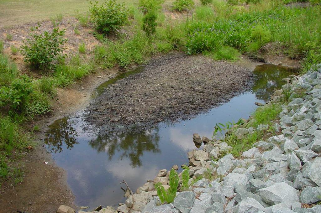
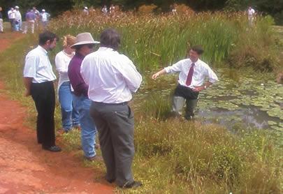
1 Hydraulic & Hydrologic Stormwater Engineering Design of Stormwater Wetlands Jon Hathaway, EI Extension Associate NCSU Bio. And Ag. Engineering
2
3 6 Step Process 1. Watershed Analysis (Runoff Volume and Peak Flow) 2. Determine H 2 0 Storage Volume 3. Calculate Surface Area 4. Size Drawdown Orifice 5. Size Overflow Weir 6. Diagram Internal Features
4 Additional Topics 1. Perch or Excavate to Water Table? 2. Bypass or Flow-Through? 3. Forebay Design
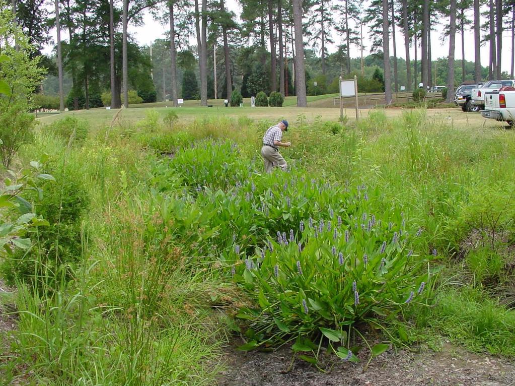
5 Watershed Analysis (Determine Treatment Volume)

6 Watershed Analysis
7 Determine Volume * Fact Finding * Watershed Area Watershed Land Use(s) Soil Type(s) within Watershed Soil Hydrologic Group» Use Land Use Map & County Soil Survey» Verify soils data in the field
8 Determine Volume * Calculate Runoff from Curve Number * (SCS Curve Number Method) P = Precipitation CN = Curve Number S = Storage Component Determined from CN R/O = Runoff
9 Determine Volume * Describing Land Use * Curve Numbers - Relate Land Use and Soil Hydrologic Group Range from 30 to 100 Higher Number = More Runoff» USDA-NRCS Tables
10 Curve Numbers Soil Group Land Use A B C D Paved Parking Lots; Roofs Commercial & Bus. Distr Townhouses Residential Lot (1/2 AC) Residential Lot (1 AC) Open Space: grass > 75%
11 Curve Numbers Keep Separate or Composite? NCSU suggests Discrete Method for Urban Watersheds Base Decision upon Soil Type Differences within watershed & Land Use May Use Composite for Watersheds with low Imperviousness (< 10%) Is Land Use Separation Distinct or Mixed Connected Imperviousness
12 Curve Numbers If Discrete: Calculate runoff from impervious areas separately determine composite for rest of watershed and calculate runoff (Can calculate for each land use in watershed if desired) If Composite: CN comp = %W a CN a + %W b CN b +...
13 Determine Volume Decide Design Storm Calculate Runoff from Impervious and Pervious land uses Use Watershed Area to Find Total Runoff
14 Determine Volume * Decide Design Storm * Varies from 0.5 to 1.5 Retrofit versus New Development Depends upon Built upon area, wetness P = 1.0 in. Old Typical Can be sized based on Water Quality Storm (earlier presentation)
15 Determine Volume * Calculate Runoff from Curve Number * (SCS Curve Number Method) P = Precipitation CN = Curve Number S = Storage Component R/O = Runoff
16 Determine Volume * Calculate Runoff from Curve Number * S = 1000 CN 10 R/O = (P - 0.2S) 2 (P + 0.8S)
17 Determine Volume Simple Method? Imp% = Percent Imperviousness in Watershed P = Depth of Rainfall (in) RO = Depth of Runoff (in) V = Volume of Runoff (ft 3 ) A = Area of Watershed (ft 2 ) V = ((Imp%*0.9) ) * P * A
18 Determine Volume 70,000 Runoff Volume (ft3) 60,000 50,000 40,000 30,000 20,000 10,000 Composite CN Discrete Simple 0 1 Precipitation Depth (in)
19 Determine Volume * Example * Given: Total Watershed Area = 35 AC 20 AC is school (soil group B) 15 AC is fair condition grass (soil group C) Find: Volume of Water to be Treated if P=1.5
20 Determine Volume * Example * Runoff Per Land Use/Soil Type: School CN = 88 S = 1000/88-10 = 1.36 Field CN = 79 S = 1000/79-10 = 2.66
21 Determine Volume * Example * Runoff Per Land Use/Soil Type: School R/O = ( *1.36) 2 ( *1.36)= 0.58 in Field R/O = ( *2.66) 2 ( *1.36)= 0.26 in
22 Determine Volume * Example * Runoff Per Land Use/Soil Type: Volume of School R/O = 0.58 in * 20 AC = 11.6 ac-in Volume of Field R/O = 0.26 in * 15 AC = 3.9 ac-in Total R/O = Volume to Treat = 15.5 ac-in Or (1.3 ac-ft)
23 Watershed Analysis (Determine Peak Flow)
24 Peak Flow during Large Storms On large systems or high risk, detailed modeling would be appropriate Need to make sure that outlet can pass the peak flow from a large storm Use Rational Method May not be accurate, be sure to include factor of safety Widely used despite downfalls
25 What is Peak Flow? Largest amount of flow experienced during a given storm dishcarge (cfs) /16/03 12/17/03 12/18/03 12/19/03
26 Rational Method Basic Equation: Q p = C * I * A Where: Q p = Peak flow (cfs) C = Rational Coefficient (composite) I = Rainfall Intensity (in / hr) A = Watershed Area (acres)
27 Rational Coefficient Similar to Curve Number Variable with land use Composite for given watershed The higher the rational coefficient the higher the peak flow
28 Rainfall Intensity Varies depending on storm size Typically duration used is either 6 hour (safe estimate) or 24 hour See Handout (State of NC Erosion and Sediment Control Planning and Design Manual)
29 From Our Earlier Example Intensity (Greensboro): Choose 2 year event 6 hour = ~0.36 in/hr Rational Coefficient: School = 0.6 Field = 0.15 Composite = (0.6 * 20 acres) + (0.15 * 15 acres) 35 acres Composite = 0.41
30 From Our Earlier Example Q p = C * I * A Q p = 0.41 * 0.36 in/hr * 35 acres Q p = ~ 5.2 cfs
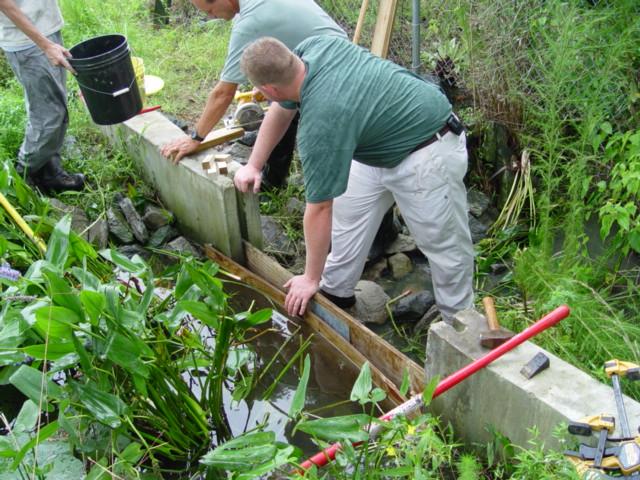
31 Calculate Surface Area

32 Calculate Surface Area
33 Calculate Surface Area Function of Volume and Allowable Depth Capture Volume Previously Determined Allowable Depth of Water Varies from 6 to 18 * 12 suggested *
34 Wetland Volumes Wetland Cross Section Definition of Storage Depths Peak Mitigation (or extra) Volume Normal Pool First Flush Volume
35 Calculate Surface Area S/A = Surface Area Required Volume = Total Volume Captured Depth = Depth of water over normal pool (Depth of Storage Volume) S/A = Volume Depth
36 Calculate Surface Area * Earlier Example * Given: Volume 15.5 ac-in Depth = 9 in Find: Surface Area of Wetland
37 Calculate Surface Area * Example * Find Surface Area S/A = 15.5 ac-in 9 in S/A = 1.7 AC
38 Calculate Surface Area Remember!! Account for some additional surface area if you are bypassing larger storms
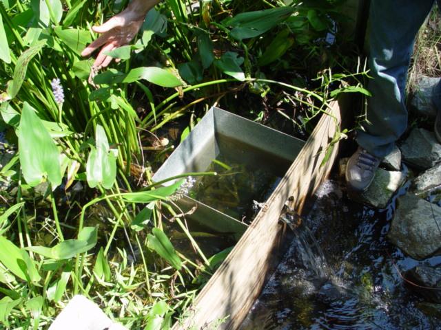
39 Size Outlet
40 Retaining Stormwater How Long Can Water stay in wetland (above normal pool)? Plant Tolerance Rainfall Event Frequency Mean time between events = 3 days 2-4 days reasonable
41 Retaining Stormwater Common Devices Used to Retain Stormwater : Orifice (draw down) Weir (overflow) (Flashboard Riser?)
42 Retaining Stormwater Weir Equation Q = Flow over Weir C w = Weir Coefficient (Commonly - 3.0) L = Length of Weir H = Height of Water upstream of weir
43 Retaining Stormwater * Devices Used to Retain Stormwater * Weir Equation Q = C w * L * H 3/2
44 Flow over Weir H 2/3 H Weir
45 Retaining Stormwater Orifice Equation Q = Flow through Orifice N = Number of Orifices (holes) C d = Coefficient of Discharge (Commonly 0.6) A = Area of Opening g = Gravity (32.2 ft/s 2 ) H = Water Height over Orifice Centerline


 1/2 )")
46 Retaining Stormwater * Device Used to Retain Stormwater * Orifice Equation Q = N * (Cd * A * (2*g*H) 1/2 )
47 Retaining Stormwater How Long to Empty Wetland of Treatment Volume? Quick & Dirty Method: 1. Calculate Flow rate at 1/3 Full Height 2. Divide this Flow rate into Total Volume
48 Retaining Stormwater * Earlier Example * Given: Wetland Storage (above Normal Pool) = 56,000 cubic feet (15.5 ac-in) Size of drawdown orifice = 5 inches Height of Water over orifice = 12 in Find: Amount of Time to Release Storage
49 Retaining Stormwater Time to Release Storage: 1. Flow over weir when 1/3 full Q = N * (Cd * A * (2*g*H) 1/2 ) 2*g*H = 2 * 32.2 ft/s2 * 0.33 ft = 21.3 Q = 1 * (0.6 * 0.14 ft 2 * (21.3) 1/2 ) = 0.39 cfs
50 Retaining Stormwater Time to Release Treatment Volume: 2. Time to Release Water Time = Vol / Discharge Rate Time = 56,000 cf / 0.39 cfs Time = 91,900 s = 40 hours
51 Retaining Stormwater Bypass larger storms What Size?? Designer choice based on risk Cost of failure Safety of individuals living in area Monetary cost Must be able to pass peak flow for chosen storm Watershed Peak Flow = Peak Wetland Outflow
52 Retaining Stormwater * Earlier Example * Overflow Weir Sizing 2 year Peak Flow = 5.2 cfs Will allow 6 inches over weir during event (Infrequent event, should not impact vegetation)
53 Retaining Stormwater Water will leave through: drawdown orifice overflow weir The outflow from these two devices combined should be 5.2 cfs
54 Retaining Stormwater Flow through Orifice Total depth over orifice is 18 inches Q = N * (Cd * A * (2*g*H)1/2) 2*g*H = 2 * 32.2 ft/s 2 * 0.67 ft = 43.1 Q = 1 * (0.6 * 0.14 ft2 * (43.1) 1/2 ) Q = 0.55 cfs
55 Retaining Stormwater Need to route 5.2 cfs - have 0.55 cfs routed through orifice - Weir must handle 4.65 cfs Q = C w * L * H 3/2 Or L = Q / (C w * H 3/2 )
56 Retaining Stormwater L = Q / (C w * H 3/2 ) L = 4.65 cfs (3.0 * (0.5 ft) 3/2 ) L = 4.38 ft (should include factor of safety) L = 4.38 * 1.2 = 5.26 L = 5.3 ft
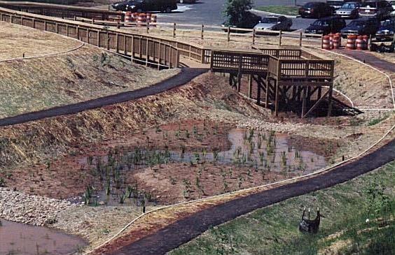
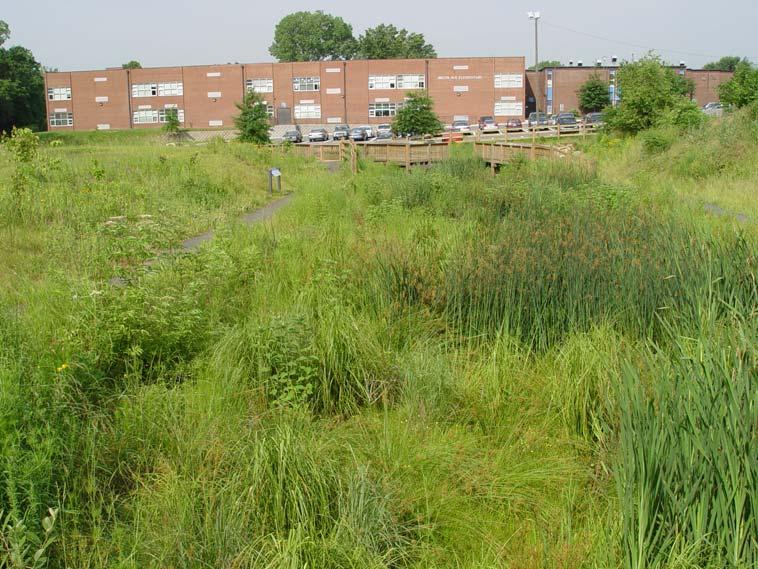
57 Diagram Internal Features
58
59 Stormwater Wetland Features Shallow Water Upland Shallow Land Outlet Forebay Deep Pools
60
61 Revised Ponding Depths Deep Shallow Shallow Pool Water Land


62 How much of Each? 10-20% 30-40% 40-60%
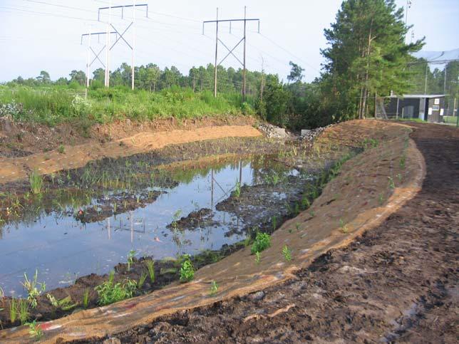
63 Perch or Excavate to Water Table?

64 Perch or Excavate to W.T.?
65 Perch or Excavate to W.T.? Determine Soil Type at W/L Site What is Seasonally Low Water Table? > 4 - You choose < 4 - Excavate to 6 below W. T. Highly dependent on Soil Conditions Dependent on Desired Cost of Construction Clay Liner
66 Perch or Excavate to W.T.? Determine Soil Type at W/L Site What is Permeability? in/hr, Compact Necessary > 0.2 in/hr, Import Clay & Compact Want K < 0.01 in/hr

67 Perch or Excavate to W.T.? * Summary * If Seasonally Low Water Table at or near Surface - Excavate. If not, Perch.

68 Perch or Excavate to W.T.?
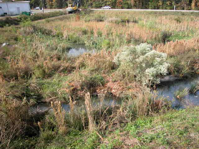
69 Bypass or Flow-Through?

70
71 Water Bypass Bypass Large Storms? Flow Through Main Body?

72 Bypass or Not? If Actual Surface Area > 0.80 of Required Design Surface Area, you do NOT need to bypass flow
73 Flow Splitter Emergency Spillway 2-Yr Storm Pool Bypass Weir Normal Pool Drawdown Orifice
74 What Size Storm? None. All storms through Wetland It depends Moderate Event. 2-YR Storm Extreme Event YR Storm All Storms > First Flush Event Bypass Wetland
75 Forebay Design
76
77 Forebay Design

78 Forebay Design More Information on the Way!!!
79 Questions?
Treatment Volume: Curve Numbers. Composite CN or Not? Treatment Volume: Curve Numbers. Treatment Volume: Calculation. Treatment Volume: Calculation
 Stormwater Engineering Bioretention Design Bill Hunt, PE, Ph.D. Extension Specialist & Assistant Professor NCSU-BAE www.bae.ncsu.edu/stormwater Bioretention Design Six Step Process 1 Determine Volume to
INFLOW DESIGN FLOOD CONTROL SYSTEM PLAN PLANT GREENE COUNTY ASH POND ALABMA POWER COMPANY
 INFLOW DESIGN FLOOD CONTROL SYSTEM PLAN PLANT GREENE COUNTY ASH POND ALABMA POWER COMPANY Section 257.82 of EPA s regulations requires the owner or operator of an existing or new CCR surface impoundment
RETENTION BASIN EXAMPLE
 -7 Given: Total Tributary Area = 7.5 ac o Tributary Area within Existing R/W = 5.8 ac o Tributary Area, Impervious, Outside of R/W = 0.0 ac o Tributary Area, Pervious, Outside of R/W = 1.7 ac o Tributary
INFLOW DESIGN FLOOD CONTROL SYSTEM PLAN PLANT BARRY ASH POND ALABAMA POWER COMPANY
 INFLOW DESIGN FLOOD CONTROL SYSTEM PLAN PLANT BARRY ASH POND ALABAMA POWER COMPANY Section 257.82 of EPA s regulations requires the owner or operator of an existing or new CCR surface impoundment or any
INITIAL RUN-ON AND RUN-OFF CONTROL PLAN 40 C.F.R. PART 257
 INITIAL RUN-ON AND RUN-OFF CONTROL PLAN 40 C.F.R. PART 257.81 PLANT BOWEN PRIVATE INDUSTRY SOLID WASTE DISPOSAL FACILITY (ASH LANDFILL) GEORGIA POWER COMPANY EPA s Disposal of Coal Combustion Residuals
INFLOW DESIGN FLOOD CONTROL SYSTEM PLAN PLANT GASTON GYPSUM POND ALABAMA POWER COMPANY
 INFLOW DESIGN FLOOD CONTROL SYSTEM PLAN PLANT GASTON GYPSUM POND ALABAMA POWER COMPANY Section 257.82 of EPA s regulations requires the owner or operator of an existing or new CCR surface impoundment or
INFLOW DESIGN FLOOD CONTROL SYSTEM PLAN 40 C.F.R. PART PLANT YATES ASH POND 3 (AP-3) GEORGIA POWER COMPANY
 GEORGIA POWER COMPANY") INFLOW DESIGN FLOOD CONTROL SYSTEM PLAN 40 C.F.R. PART 257.82 PLANT YATES ASH POND 3 (AP-3) GEORGIA POWER COMPANY EPA s Disposal of Coal Combustion Residuals from Electric Utilities Final Rule (40 C.F.R.
INFLOW DESIGN FLOOD CONTROL SYSTEM PLAN 40 C.F.R. PART 257.82 PLANT YATES ASH POND 3 (AP-3) GEORGIA POWER COMPANY EPA s Disposal of Coal Combustion Residuals from Electric Utilities Final Rule (40 C.F.R.
Pre-Treatment Bioretention Cells Bioswales IOWA STORMWATER MANAGEMENT MANUAL DECEMBER 16, 2015
 Pre-Treatment Bioretention Cells Bioswales IOWA STORMWATER MANAGEMENT MANUAL DECEMBER 16, 2015 Urban Runoff Background How we got here What Problem?? Provenance of the Problem Unified Sizing Criteria What
RUN-ON AND RUN-OFF CONTROL PLAN 40 C.F.R. PART PLANT DANIEL NORTH ASH MANAGEMENT UNIT MISSISSIPPI POWER COMPANY
 RUN-ON AND RUN-OFF CONTROL PLAN 40 C.F.R. PART 257.81 PLANT DANIEL NORTH ASH MANAGEMENT UNIT MISSISSIPPI POWER COMPANY EPA s Disposal of Coal Combustion Residuals from Electric Utilities Final Rule (40
BMP Design Aids. w w w. t r a n s p o r t a t i o n. o h i o. g o v. Equations / Programs
 BMP Design Aids 1 Equations / Programs Outlet Discharge Equations Hydrograph and Pond Routing Programs USGS StreamStats 2 Ohio Department of Transportation 1 Training Intent Introduction and overview of
Modeling Infiltration BMPs
 Modeling Infiltration BMPs CAHILL ASSOCIATES Environmental Consultants West Chester, PA (610) 696-4150 www.thcahill.com Design Goals for Calculations 1. Mitigate Peak Rates 2-Year to 100-Year 2. No Volume
Design Example Residential Subdivision
 Design Example Residential Subdivision Rhode Island Stormwater Design and Installation Standards Manual December 2010 Public Training March 22, 2010 Richard Claytor, P.E. 508-833-6600 Appendix D: Site
Example 1: Pond Design in a residential development (Water Quantity calculations for a Wet Pond and Wet Extended Detention Pond)
") Chapter 10 Design Examples Example 1: Pond Design in a residential development (Water Quantity calculations for a Wet Pond and Wet Extended Detention Pond) Example 2: Filter Design in a commercial development
Chapter 10 Design Examples Example 1: Pond Design in a residential development (Water Quantity calculations for a Wet Pond and Wet Extended Detention Pond) Example 2: Filter Design in a commercial development
INFLOW DESIGN FLOOD CONTROL SYSTEM PLAN 40 C.F.R. Part PLANT MCINTOSH ASH POND 1 GEORGIA POWER COMPANY
 INFLOW DESIGN FLOOD CONTROL SYSTEM PLAN 40 C.F.R. Part 257.82 PLANT MCINTOSH ASH POND 1 GEORGIA POWER COMPANY EPA s Disposal of Coal Combustion Residuals from Electric Utilities Final Rule (40 C.F.R. Part
Rational Method Hydrological Calculations with Excel COURSE CONTENT
 Rational Method Hydrological Calculations with Excel Harlan H. Bengtson, PhD, P.E. COURSE CONTENT 1. Introduction Calculation of peak storm water runoff rate from a drainage area is often done with the
Appendix A. Compliance Calculator Guidance
 Compliance Calculator Guidance Appendix A Appendix A. Compliance Calculator Guidance A.1 Introduction The Center for Watershed Protection created the compliance calculator spreadsheet to allow a designer
INITIAL RUN-ON AND RUN-OFF CONTROL PLAN 40 C.F.R. PART 257
 INITIAL RUN-ON AND RUN-OFF CONTROL PLAN 40 C.F.R. PART 257.81 HUFFAKER ROAD (PLANT HAMMOND) PRIVATE INDUSTRIAL LANDFILL (HUFFAKER ROAD LANDFILL) GEORGIA POWER COMPANY EPA s Disposal of Coal Combustion
Rhode Island Stormwater Design and Installations Standards Manual
 Rhode Island Stormwater Design and Installations Standards Manual Public Workshop Required Management Volume Calculations and Redevelopment Considerations March 22, 2011 Presentation Outline Recap of How
Ponds. Pond A water impoundment made by excavating a pit, or constructing a dam or an embankment.
 POND SITE SELECTION AND CONSTRUCTION Uses, Planning, & Design David Krietemeyer Area Engineer USDA-NRCS June 20, 2008 Uses Considerations for Location of Commonly Used Terms Pond A water impoundment made
Detention Pond Design Considering Varying Design Storms. Receiving Water Effects of Water Pollutant Discharges
 Detention Pond Design Considering Varying Design Storms Land Development Results in Increased Peak Flow Rates and Runoff Volumes Developed area Robert Pitt Department of Civil, Construction and Environmental
Green Infrastructure Flood Reduction Computations
 Green Infrastructure Flood Reduction Computations Stephen Sands, PE, CFM ssands@hazenandsawyer.com March 24, 2016 Water JAM 2010 Discussion Topics Siting success Watershed-wide computations Individual
How Climate Change Impacts Urban Runoff and Water Quality Design
 How Climate Change Impacts Urban Runoff and Water Quality Design by J. C. Hayes, C. Privette, III and S. J. Klaine AWRA Conference Anchorage, AK May 4-7, 2009 Presentation Outline Introduction: Why manage
Natural and Engineered Wetlands for Stormwater Management
 Natural and Engineered Wetlands for Stormwater Management Dan Hitchcock, Ph.D., P. E. Baruch Institute of Coastal Ecology and Forest Science Clemson University Georgetown, SC Prominence and Diversity of
Extended Detention Basin Design
 Extended Detention Basin Design 1 Extended Detention 2 Ohio Department of Transportation 1 Extended Detention Basin L&D Vol. 2 Section 1117.3 Provides quality and quantity treatment 3 Extended Detention
PRELIMINARY DRAINAGE STUDY
 PRELIMINARY DRAINAGE STUDY For 34 th & J Residences 3402 J St. San Diego, CA 92102 A.P.N 545-250-08 Prepared By: Kenneth J. Discenza, P.E. Site Design Associates, Inc. 1016 Broadway, Suite A El Cajon,
INFLOW DESIGN FLOOD CONTROL SYSTEM PLAN 40 C.F.R. PART PLANT DANIEL ASH POND B MISSISSIPPI POWER COMPANY
 INFLOW DESIGN FLOOD CONTROL SYSTEM PLAN 40 C.F.R. PART 257.82 PLANT DANIEL ASH POND B MISSISSIPPI POWER COMPANY EPA s Disposal of Coal Combustion Residuals from Electric Utilities Final Rule (40 C.F.R.
Appendix C.1. Design Example 1 Shallow Wetland (W-1)
") Appendix C.1 Design Example 1 Shallow Wetland (W-1) Design Example 1 Shallow Wetland (W-1) The following example demonstrates the process for the design of a shallow wetland (W-1) BMP. Site Specific Data
Appendix C.1 Design Example 1 Shallow Wetland (W-1) Design Example 1 Shallow Wetland (W-1) The following example demonstrates the process for the design of a shallow wetland (W-1) BMP. Site Specific Data
Shelbyville, Kentucky Stormwater Best Management Practices (BMPs) Stormwater Pollution Treatment Practices (Structural) DRAFT
 Stormwater Pollution Treatment Practices (Structural) DRAFT") Shelbyville, Kentucky Stormwater Best Management Practices (BMPs) Stormwater Pollution Treatment Practices (Structural) Activity: Infiltration Systems PLANNING CONSIDERATIONS: Design Life: Short IS Acreage
Shelbyville, Kentucky Stormwater Best Management Practices (BMPs) Stormwater Pollution Treatment Practices (Structural) Activity: Infiltration Systems PLANNING CONSIDERATIONS: Design Life: Short IS Acreage
CE 585. Construction Site Erosion Control. The University of Alabama. Tuscaloosa, AL. New Chevrolet and Cadillac Dealership.
 CE 585 Construction Site Erosion Control The University of Alabama Tuscaloosa, AL New Chevrolet and Cadillac Dealership Jasper, AL Andrew Kennedy July 10, 2007 0 Table of Contents 1. Introduction.. 1 2.
Chatham Park Stormwater Manual
 Chatham Park Stormwater Manual Table of Contents A. Introduction... 2 B. Calculation Methods... 2 C. BMP Design Standards... 3 D. Compliance Points... 3 E. Critical Environmental Resources... 3 F. Submittal
Activity Calculating Property Drainage
 Page 1 of 5 Activity 2.3.11 Calculating Property Drainage Introduction When a property is developed, it is important to understand that changes to watershed characteristics (i.e., land use, slope, soil
Drainage Analysis. Appendix E
 Drainage Analysis Appendix E The existing and proposed storm drainage systems have been modeled with Bentley CivilStorm V8 computer modeling software. The peak stormwater discharge was determined for
CVEN 339 Summer 2009 Final Exam. 120 minutes allowed. 36 Students. No curve applied to grades. Median 70.6 Mean 68.7 Std. Dev High 88 Low 24.
 CVEN 339 Final Exam 120 minutes allowed 36 Students No curve applied to grades Median 70.6 Mean 68.7 Std. Dev. 13.7 High 88 Low 24.5 Name: CVEN 339 Water Resources Engineering Summer Semester 2009 Dr.
Rainfall, Runoff and Peak Flows: Calibration of Hydrologic Design Methods for the Kansas City Area
 Rainfall, Runoff and Peak Flows: Calibration of Hydrologic Design Methods for the Kansas City Area Bruce McEnroe, Bryan Young, Ricardo Gamarra and Ryan Pohl Department of Civil, Environmental, and Architectural
INFLOW DESIGN FLOOD CONTROL SYSTEM PLAN 40 C.F.R. PART PLANT YATES ASH POND B (AP-B ) GEORGIA POWER COMPANY
 GEORGIA POWER COMPANY") INFLOW DESIGN FLOOD CONTROL SYSTEM PLAN 40 C.F.R. PART 257.82 PLANT YATES ASH POND B (AP-B ) GEORGIA POWER COMPANY EPA s Disposal of Coal Combustion Residuals from Electric Utilities Final Rule (40 C.F.R.
INFLOW DESIGN FLOOD CONTROL SYSTEM PLAN 40 C.F.R. PART 257.82 PLANT YATES ASH POND B (AP-B ) GEORGIA POWER COMPANY EPA s Disposal of Coal Combustion Residuals from Electric Utilities Final Rule (40 C.F.R.
Concurrent Session B: LID Design Specifications (Chapter 4 in Draft Manual)
") Concurrent Session B: LID Design Specifications (Chapter 4 in Draft Manual) Should vs. Must In Chapter 4, should means should, and must means must. Poorly Drained Soils Well-Drained Soils Flat Terrain
Concurrent Session B: LID Design Specifications (Chapter 4 in Draft Manual) Should vs. Must In Chapter 4, should means should, and must means must. Poorly Drained Soils Well-Drained Soils Flat Terrain
Appendix F. Flow Duration Basin Design Guidance
 Appendix F Flow Duration Basin Design Guidance Appendix F FINAL REPORT F:\SC46\SC46.31\HMP Mar 05\Appendices\Appendix F FLY_HMP.doc MARCH 2005 Appendix F Flow Duration Basin Design Guidance Prepared by
Hydrologic Study Report for Single Lot Detention Basin Analysis
 Hydrologic Study Report for Single Lot Detention Basin Analysis Prepared for: City of Vista, California August 18, 2006 Tory R. Walker, R.C.E. 45005 President W.O. 116-01 01/23/2007 Table of Contents Page
Urbanizing Watersheds: Green Infrastructure and Hydrologic Function. Jay Dorsey, PE, PhD ODNR-DSWR October 30, 2014
 Urbanizing Watersheds: Green Infrastructure and Hydrologic Function Jay Dorsey, PE, PhD ODNR-DSWR October 30, 2014 Green Infrastructure Objectives Intentional about maintaining/replacing ecosystem functions
APPENDIX F RATIONAL METHOD
 7-F-1 APPENDIX F RATIONAL METHOD 1.0 Introduction One of the most commonly used procedures for calculating peak flows from small drainages less than 200 acres is the Rational Method. This method is most
INFLOW DESIGN FLOOD CONTROL SYSTEM PLAN 40 C.F.R. PART PLANT BOWEN ASH POND 1 (AP-1) GEORGIA POWER COMPANY
 GEORGIA POWER COMPANY") INFLOW DESIGN FLOOD CONTROL SYSTEM PLAN 40 C.F.R. PART 257.82 PLANT BOWEN ASH POND 1 (AP-1) GEORGIA POWER COMPANY EPA s Disposal of Coal Combustion Residuals from Electric Utilities Final Rule (40 C.F.R.
INFLOW DESIGN FLOOD CONTROL SYSTEM PLAN 40 C.F.R. PART 257.82 PLANT BOWEN ASH POND 1 (AP-1) GEORGIA POWER COMPANY EPA s Disposal of Coal Combustion Residuals from Electric Utilities Final Rule (40 C.F.R.
CENTRALIZED BMPS TYPICALLY PUBLICLY OWNED & MAINTAINED BMPS, TREATING A LARGE (>20 ACRES) URBAN DRAINAGE WITH MULTIPLE LAND
 URBAN DRAINAGE WITH MULTIPLE LAND") BMP RAM BMP Type Definitions 1 CENTRALIZED BMPS TYPICALLY PUBLICLY OWNED & MAINTAINED BMPS, TREATING A LARGE (>20 ACRES) URBAN DRAINAGE WITH MULTIPLE LAND USES AND OWNERSHIP STRUCTURAL BMP TYPE OTHER NAMES
BMP RAM BMP Type Definitions 1 CENTRALIZED BMPS TYPICALLY PUBLICLY OWNED & MAINTAINED BMPS, TREATING A LARGE (>20 ACRES) URBAN DRAINAGE WITH MULTIPLE LAND USES AND OWNERSHIP STRUCTURAL BMP TYPE OTHER NAMES
Module 6 Temporary Pond and Silt Fence. Noboru Togawa. Presented to: Dr. Pitt Construction Site Erosion Control
 Module 6 Temporary Pond and Silt Fence by Presented to: Dr. Pitt Construction Site Erosion Control Department of Civil, Construction, and Environmental Engineering The University of Alabama Tuscaloosa,
Surface Skimmer and Baffle Sediment Basins, Modeling the Benefits
 Surface Skimmer and Baffle Sediment Basins, Modeling the Benefits J.P. Johns, PE Woolpert Ray Vaughan Stormwater Manager SCDOT Brandon Wagner -Woolpert Background o SCDOT sediment basin design required
HYDROLOGIC CONSIDERATIONS. 22 nd Annual Nonpoint Source Pollution Conference Saratoga Springs, NY
 LOW IMPACT DEVELOPMENT HYDROLOGIC CONSIDERATIONS 22 nd Annual Nonpoint Source Pollution Conference Saratoga Springs, NY May 18, 2011 PRESENTATION AGENDA Introduction Definitions Discuss Impacts to Hydrologic
Water Resources Management Plan
 P L Y M O U T H M I N N E S O T A Appendix D: The developed a to analyze and minimize the impact of existing and future development on the City s natural resources. It is important to the City to have
APPENDIX IV. APPROVED METHODS FOR QUANTIFYING HYDROLOGIC CONDITIONS OF CONCERN (NORTH ORANGE COUNTY)
") APPENDIX IV. APPROVED METHODS FOR QUANTIFYING HYDROLOGIC CONDITIONS OF CONCERN (NORTH ORANGE COUNTY) Hydromodification design criteria for the North Orange County permit area are based on the 2- yr, 24-hr
APPENDIX IV. APPROVED METHODS FOR QUANTIFYING HYDROLOGIC CONDITIONS OF CONCERN (NORTH ORANGE COUNTY) Hydromodification design criteria for the North Orange County permit area are based on the 2- yr, 24-hr
ORDINANCE APPENDIX F STORMWATER MANAGEMENT DESIGN CRITERIA
 ORDINANCE APPENDIX F STORMWATER MANAGEMENT DESIGN CRITERIA TABLE F-1 DESIGN STORM RAINFALL AMOUNT FIGURE F-1 ALTERNATING BLOCK METHOD FOR RAINFALL DISTRIBUTION FIGURE F-2 PENNDOT DELINEATED REGIONS FIGURE
Hydrology for Drainage Design. Design Considerations Use appropriate design tools for the job at hand:
 Hydrology for Drainage Design Robert Pitt Department of Civil and Environmental Engineering University of Alabama Tuscaloosa, AL Objectives for Urban Drainage Systems are Varied Ensure personal safety
Hydromodification Management Measures
 Chapter 7 Hydromodification Management Measures This Chapter summarizes the requirements for controlling erosive flows from development projects. 7.1 Why Require Hydromodification Management? Changes in
Hydromodification Management Measures
 Chapter 7 Hydromodification Management Measures This Chapter summarizes the requirements for controlling erosive flows from development projects. 7.1 Why Require Hydromodification Management? Changes in
FAST WATER / SLOW WATER AN EVALUATION OF ESTIMATING TIME FOR STORMWATER RUNOFF
 FAST WATER / SLOW WATER AN EVALUATION OF ESTIMATING TIME FOR STORMWATER RUNOFF Factors Affecting Stormwater Runoff: Rainfall intensity % Impervious surfaces Watershed size Slope Soil type, soil compaction
CHAPTER 3 STORMWATER HYDROLOGY. Table of Contents SECTION 3.1 METHODS FOR ESTIMATING STORMWATER RUNOFF
 CHAPTER 3 STORMWATER HYDROLOGY Table of Contents SECTION 3.1 METHODS FOR ESTIMATING STORMWATER RUNOFF 3.1.1 Introduction to Hydrologic Methods...3.1-1 3.1.2 Symbols and Definitions...3.1-3 3.1.3 Rainfall
San Francisco State University Site 1 Vegetated Infiltration Basin Monitoring Report: Rainy Seasons and
 San Francisco State University Site 1 Vegetated Infiltration Basin Monitoring Report: Rainy Seasons 2011-12 and 2012-13 Project Overview San Francisco State University (SFSU) has implemented several green
6.5 Extended Detention Basin
 6.5 Extended Detention Basin Figure 6-22: Extended Detention Basin. Photograph courtesy of Bill Southard (DES Architects and Engineers) Best uses Detain low flows Can be expanded to detain peak flows Sedimentation
Sediment Basins and Skimmers. Jay Dorsey/John Mathews Ohio Dept. of Natural Resources, Division of Soil and Water Resources
 Sediment Basins and Skimmers Jay Dorsey/John Mathews Ohio Dept. of Natural Resources, Division of Soil and Water Resources Dewatering Risers in Basins: Single orifice Perforated and wrapped riser And now
INITIAL INFLOW DESIGN FLOOD CONTROL SYSTEM PLAN PLANT MCMANUS ASH POND A (AP-1) 40 CFR
 40 CFR") INITIAL INFLOW DESIGN FLOOD CONTROL SYSTEM PLAN PLANT MCMANUS ASH POND A (AP-1) 40 CFR 257.82 EPA s Disposal of Coal Combustion Residuals from Electric Utilities Final Rule (40 C.F.R. Part 257 and Part
INITIAL INFLOW DESIGN FLOOD CONTROL SYSTEM PLAN PLANT MCMANUS ASH POND A (AP-1) 40 CFR 257.82 EPA s Disposal of Coal Combustion Residuals from Electric Utilities Final Rule (40 C.F.R. Part 257 and Part
SITE DESIGN ENGINEERING, LLC. 11 Cushman Street, Middleboro, MA P: F:
 INTRODUCTION This drainage report was prepared for the proposed site re-development at in Burlington, Massachusetts. The project site is approximately 1.05± acres consisting of approximately 70% impervious
Ponds Planning, Design, Construction
 United States Department of Agriculture Natural Resources Conservation Service Ponds Planning, Design, Construction Agriculture Handbook Number 590 Estimating storm runoff The amount of precipitation,
GENERAL AND FLOODING STANDARDS SUBMISSION BRUNSWICK LAYOVER FACILITY BRUNSWICK, MAINE PREPARED FOR:
 APPENDIX H GENERAL AND FLOODING STANDARDS SUBMISSION BRUNSWICK LAYOVER FACILITY BRUNSWICK, MAINE PREPARED FOR: NORTHERN NEW ENGLAND PASSENGER RAIL AUTHORITY (NNEPRA) 75 WEST COMMERCIAL STREET, SUITE 104
CHAPTER 3 Water Quality Standards
 Table of Contents CHAPTER 3 Water Quality Standards 3.1 Water Quality Protection Approach... 3-1 3.2 General Policies... 3-2 3.3 Water Quality Management... 3-2 3.3.1 Minimum Standard and General Policies...3-2
Modeling the Hydrologic Impacts of Control Structures Utilizing LiDAR, ICPR, and GIS Technologies
 Modeling the Hydrologic Impacts of Control Structures Utilizing LiDAR, ICPR, and GIS Technologies Keanan Bell NorthStar June 12, 2015 Project began in 2010 as a Hydrology Assessment and Conceptual Restoration
SAN GORGONIO PASS CAMPUS - PHASE I
 SAN GORGONIO PASS CAMPUS - PHASE I Banning, CA DRAINAGE STUDY June 16, 2010 Reference 106-195 PREPARED BY: Encompass Associates, Inc. 5699 Cousins Place Rancho Cucamonga, CA 91737 909-684-0093 Fax-909-586-6979
Chapter 6. Hydrology. 6.0 Introduction. 6.1 Design Rainfall
 6.0 Introduction This chapter summarizes methodology for determining rainfall and runoff information for the design of stormwater management facilities in the City. The methodology is based on the procedures
Peak discharge computation
 Ia/P 4 Peak Dischage Method Graphical Peak Discharge Method This chapter presents the Graphical Peak Discharge method for computing peak discharge from rural and urban areas. The Graphical method was developed
Krista Reininga, PE Hydromodification and What it Means for the Design of Stormwater Facilities
 Krista Reininga, PE Hydromodification and What it Means for the Design of Stormwater Facilities Agenda 1. Evolution of Water Quality Facilities 2. Regulatory Response/MS4 Permit Requirements 3. Change
DESIGN HYDROLOGY MANUAL
 DESIGN HYDROLOGY MANUAL 2010 ERRATA PAGES VENTURA COUNTY WATERSHED PROTECTION DISTRICT VENTURA COUNTY, CALIFORNIA JUNE, 2011 DISTRICT CONTACTS: Design Hydrologist: VCRat Programmer Reviewer: District Director:
APPENDIX E APPENDIX E ESTIMATING RUNOFF FOR SMALL WATERSHEDS
 APPENDIX E ESTIMATING RUNOFF FOR SMALL WATERSHEDS March 18, 2003 This page left blank intentionally. March 18, 2003 TABLES Table E.1 Table E.2 Return Frequencies for Roadway Drainage Design Rational Method
Applying the Water Quality Volume
 Applying the Water Quality Volume Justin Reinhart, PE Division of Surface Water Northeast Ohio Stormwater Training Council Cleveland, Ohio & Richfield, Ohio July 12, 2018 July 25, 2018 Post-Construction
Preliminary Drainage Analysis
 Preliminary Drainage Analysis Tanimura and Antle Employee Housing Town of Spreckels County of Monterey, California LIB150205 May 29, 2015 Prepared For: Tanimura and Antle Produce Prepared By: 9699 Blue
6.0 Runoff. 6.1 Introduction. 6.2 Flood Control Design Runoff
 October 2003, Revised February 2005 Chapter 6.0, Runoff Page 1 6.1 Introduction 6.0 Runoff The timing, peak rates of discharge, and volume of stormwater runoff are the primary considerations in the design
Redevelopment Introduction
 Redevelopment 11 11.1 Introduction Design standards for new development sites have been established in previous chapters of this document. Redevelopment sites, however, often present unique challenges
Module 3: Rainfall and Hydrology for Construction Site Erosion Control
 Module 3: Rainfall and Hydrology for Construction Site Erosion Control Robert Pitt Department of Civil, Construction, and Environmental Engineering University of Alabama Tuscaloosa, AL Rainfall and Hydrology
Managed Release Concept December 13, 2018
 Bureau of Clean Water Managed Release Concept Description Managed Release Concept (MRC) is a post-construction stormwater management (PCSM) strategy that involves the collection, storage, and filtration
Pennsylvania Stormwater Best Management Practices Manual. Chapter 3. Stormwater Management Principles and Recommended Control Guidelines
 Pennsylvania Stormwater Best Management Practices Manual Chapter 3 Stormwater Management Principles and Recommended Control Guidelines 363-0300-002 / December 30, 2006 Chapter 3 Stormwater Management Principles
Basic Hydrology Runoff Curve Numbers
 Basic Hydrology Runoff Curve Numbers By: Paul Schiariti, P.E., CPESC Mercer County Soil Conservation District The SCS Runoff Curve Number The RCN (Runoff Curve Number) method was originally established
SIZING. MWS Linear. Hybrid Stormwater Filtration System. P.O. Box 869 P Oceanside, CA F
 SIZING MWS Linear Hybrid Stormwater Filtration System Modular Wetland Systems, Inc. www.modularwetlands.com P.O. Box 869 P 760-433-7640 Oceanside, CA 92049 F 760-433-3179 SIZING Many municipal stormwater
LAKE COUNTY HYDROLOGY DESIGN STANDARDS
 LAKE COUNTY HYDROLOGY DESIGN STANDARDS Lake County Department of Public Works Water Resources Division 255 N. Forbes Street Lakeport, CA 95453 (707)263-2341 Adopted June 22, 1999 These Standards provide
APPENDIX A: STORMWATER HYDROLOGY
 APPENDIX A: STORMWATER HYDROLOGY In low impact development (LID), the objective of stormwater control measures (SCMs) is to mimic or replicate the hydrologic function of a natural system. This approach
OHIO S NPDES STORMWATER GENERAL PERMIT FOR CONSTRUCTION ACTIVITIES OHC Justin Reinhart, PE Division of Surface Water
 OHIO S NPDES STORMWATER GENERAL PERMIT FOR CONSTRUCTION ACTIVITIES OHC00005 Justin Reinhart, PE Division of Surface Water ASCE Spring Seminar Columbus, Ohio April 26, 2018 Goals / Outline 1. CGP background
Software Applications for Runoff Hydrological Assessment
 Bulletin UASVM Horticulture, 67(2)/2010 Print ISSN 1843-5254; Electronic ISSN 1843-5394 Software Applications for Runoff Hydrological Assessment Severin CAZANESCU 1), Sorin CIMPEANU 1), Oana GUI 2), Dana
MVP 17.3 WATER BAR END TREATMENT SIZING AND DETAILS 1/22/18
 MVP 17.3 WATER BAR END TREATMENT SIZING AND DETAILS 1/22/18 The purpose of this detail is to document the methodology developed to size the length of the water bar end treatments to ensure flow leaving
C-1. Infiltration System
 C-1. Infiltration System Design Objective An infiltration system captures surface stormwater runoff and allows it to infiltrate into the soil. This SCM is typically the work horse of a runoff volume match
LID PLANTER BOX MODELING
 LID PLANTER BOX MODELING Clear Creek Solutions, Inc., 2010 Low Impact Development (LID) planter boxes are small, urban stormwater mitigation facilities. They are rain gardens in a box. WWHM4 provides the
CHELTENHAM TOWNSHIP Chapter 290: WATERSHED STORMWATER MANAGEMENT Article IV: Stormwater Management
 CHELTENHAM TOWNSHIP Chapter 290: WATERSHED STORMWATER MANAGEMENT Article IV: Stormwater Management Online ECode Available on Cheltenham Township Website at: http://ecode360.com/14477578 For all regulated
Stormwater Management Impacts Resulting from the Volumetric Abstraction of Runoff from Frequent Storms per PADEP CG-1. Geoffrey A. Cerrelli 1, P.E.
 Stormwater Management Impacts Resulting from the Volumetric Abstraction of Runoff from Frequent Storms per PADEP CG-1 Geoffrey A. Cerrelli 1, P.E. 1 Hydraulic Engineer USDA/NRCS, One Credit Union Place,
EXAMPLE Stormwater Management Plans w/ CSS BMP Sizing Calculator (v2.1)
") 525 Golden Gate Avenue, 11th Floor San Francisco, CA 94102 EXAMPLE Stormwater Management Plans w/ CSS BMP Sizing Calculator (v2.1) The following example Stormwater Management Plans (SMPs) are provided
525 Golden Gate Avenue, 11th Floor San Francisco, CA 94102 EXAMPLE Stormwater Management Plans w/ CSS BMP Sizing Calculator (v2.1) The following example Stormwater Management Plans (SMPs) are provided
Refinement Task 19 Minne Lusa Basin Search for Hybrid Alternatives
 Refinement Task 19 Minne Lusa Basin Search for Hybrid Alternatives TO: Roger Coffey, PMT Document Control Center, CH2M Hill COPY: Jim Theiler, City of Omaha Scott Aurit, PMT Tom Heinemann, PMT FROM: Jim
SIZING CRITERIA FOR STORMWATER TREATMENT
 SIZING CRITERIA FOR STORMWATER TREATMENT Prepared for Santa Clara Valley Urban Runoff Pollution Prevention Program, and The Santa Clara Valley Water District Prepared by May 5, 2003 Page 1 of 31 5/5/2003
Names: ESS 315. Lab #6, Floods and Runoff Part I Flood frequency
 Names: ESS 315 Lab #6, Floods and Runoff Part I Flood frequency A flood is any relatively high flow of water over land that is not normally under water. Floods occur at streams and rivers but can also
2C-12 Detention Basin Outlet Structures
 Iowa Stormwater Management Manual 2C-12 2C-12 Detention Basin Outlet Structures A. Introduction The methods described in Section 2C-9 are used to estimate the volume of the detention storage. The second
Stormwater Analysis Report
 Stormwater Analysis Report Solar Panel Array Temple Street (Rt. 14) West Boylston, MA February 24, 216 SITE Prepared for: West Boylston Municipal Lighting Plant 4 Crescent Street West Boylston, MA 1583
WQ-06 SAND FILTER. 1.0 Sand Filter. Greenville County Technical Specification for: 1.1 Description
 Greenville County Technical Specification for: WQ-06 SAND FILTER 1.0 Sand Filter 1.1 Description Sand Filters remove pollutants through sedimentation and filtration within the sand. The primary components
APPENDIX E ESTIMATING RUNOFF FROM SMALL WATERSHEDS
 ESTIMATING RUNOFF FROM SMALL WATERSHEDS June 2011 THIS PAGE LEFT BLANK INTENTIONALLY. June 2011 TABLES Table E.1 Table E.2 Return Frequencies for Roadway Drainage Design Rational Method Values June 2011
iswm TM Technical Manual Hydrology:
 : 1.0 2.0 Downstream Assessment 3.0 Streambank Protection 4.0 Water Balance 5.0 Rainfall Tables 6.0 Hydrologic Soils Data Table of Contents 1.0... HO-1 1.1 Estimating Runoff... HO-1 1.1.1 Introduction
Summary of Detention Pond Calculation Canyon Estates American Canyon, California
 July 15, 2015 Bellecci & Associates, Inc Summary of Detention Pond Calculation Canyon Estates American Canyon, California 1. Methodology: Method: Unit Hydrograph Software: Bentley Pond Pack Version 8i
APPENDIX H: Reference Materials
 APPENDIX H: Reference Materials H-0 2. RUNOFF ESTIMATION 2.2.1 NRCS Curve Number The NRCS CN method relates soil type, soil cover, land use type, and antecedent moisture conditions to a CN. Excess rainfall
Sizing Calculations and Design Considerations for LID Treatment Measures
 SCVURPPP C.3 Workshop December 18, 2012 Sizing Calculations and Design Considerations for LID Treatment Measures Jill Bicknell, P.E., EOA, Inc. Santa Clara Valley Urban Runoff Pollution Prevention Program
Environmental Design Group
 SEDIMENT CONTROL DURING CONSTRUCTION, STORMWATER MANAGEMENT AND POST CONSTRUCTION BMP REPORT for Hudson Salt Storage and Bus Garage 5810 Hudson Drive HUDSON, OHIO SUMMIT COUNTY Prepared by Environmental
Dawson County Public Works 25 Justice Way, Suite 2232, Dawsonville, GA (706) x 42228
 x 42228") Dawson County Public Works 25 Justice Way, Suite 2232, Dawsonville, GA 30534 (706) 344-3500 x 42228 DAWSON COUNTY STORM WATER REVIEW CHECKLIST Project Name: Property Address: Engineer: Fax #/Email: Date:
Dawson County Public Works 25 Justice Way, Suite 2232, Dawsonville, GA 30534 (706) 344-3500 x 42228 DAWSON COUNTY STORM WATER REVIEW CHECKLIST Project Name: Property Address: Engineer: Fax #/Email: Date: