Chapter 10 POWER CYCLES. Department of Mechanical Engineering
|
|
|
- Ariel Goodman
- 5 years ago
- Views:
Transcription
1 Chapter 10 VAPOR AND COMBINED POWER CYCLES Dr Ali Jawarneh Department of Mechanical Engineering Hashemite University it
2 2
3 Objectives Analyze vapor power cycles in which h the working fluid is alternately vaporized and condensed. Analyze power generation coupled with process heating called cogeneration. Investigate ways to modify the basic Rankine vapor power cycle to increase the cycle thermal efficiency. Analyze the reheat and regenerative vapor power cycles. Analyze power cycles that consist of two separate cycles known as combined cycles and binary cycles. 3
4 10-1:THE CARNOT VAPOR CYCLE The Carnot cycle is the most efficient cycle operating between two specified temperature limits but it is not a suitable model for power cycles. Because: Process 1-2 Limiting the heat transfer processes to two-phase systems severely limits the maximum temperature that can be used in the cycle (374 C for water: triple point) Process 2-3 The turbine cannot handle steam with a high moisture content because of the impingement of liquid droplets on the turbine blades causing erosion and wear. Process 4-1 It is not practical to design a compressor that handles two phases. The cycle in (b) is not suitable since it requires isentropic compression to extremely high pressures and isothermal heat transfer at variable pressures. a steady-flow Carnot cycle executed within the saturation dome of a pure substance T-s diagram of two Carnot vapor cycles. 1-2 isothermal heat addition in a boiler 2-3 isentropic expansion in a turbine 3-4 isothermal heat rejection in a condenser 4-1 isentropic compression in a compressor Carnot cycle ideally can also be applied in closed system that consists of 4 piston cylinder device
5 EXAMPLE: A steady-flow Carnot cycle uses water as the working fluid. Water changes from saturated t liquid to saturated vapor as heat is transferred to it from a source at 250 C. Heat rejection takes place at a pressure of 20 kpa. Show the cycle on a T-s diagram relative to the saturation lines, and determine (a) the thermal efficiency, (b) the amount of heat rejected, in kj/kg, and (c) the net work output. 5
6 SOLUTION: 6
7 10-2 RANKINE CYCLE: THE IDEAL CYCLE FOR VAPOR POWER CYCLES Many of the impracticalities associated with the Carnot cycle can be eliminated by superheating the steam in the boiler and condensing it completely in the condenser. The cycle that results is the Rankine cycle, which is the ideal cycle for vapor power plants. The ideal Rankine cycle does not involve any internal irreversibilities. Area under the process curve on a T-s diagram represents the heat transfer for internally reversible processes, we see that the area under process curve 2-3 represents the heat transferred to the water in the boiler and the area under the process curve 4-1 represents the heat rejected in the condenser. The difference between these two (the area enclosed by the cycle curve) is the net work produced during the cycle. The simple ideal Rankine cycle. Water enters the pump at state 1 as saturated liquid and is compressed isentropically to the operating pressure of the boiler. The water temperature increases somewhat during this isentropic compression process due to a slight decrease in the specific volume of water. The vertical distance between states 1 and 2 on the T-s diagram is greatly exaggerated for clarity. (If water were truly incompressible, would there be a temperature change at all during this process?) 7
8 Energy Analysis of the Ideal Rankine Cycle Steady-flow energy equation The efficiency of power plants in the U.S. is often expressed in terms of heat rate, which is the amount of heat supplied, in Btu s, to generate 1 kwh of electricity. 1 kwh = 3412 Btu The thermal efficiency can be interpreted as the ratio of the area enclosed by the cycle on a T-s diagram to the area under the heat-addition process. 8
9 EXAMPLE: A steam power plant operates on a simple ideal Rankine cycle between the pressure limits of 3 MPa and 50 kpa. The temperature of the steam at the turbine inlet is 300 C, and the mass flow rate of steam through the cycle is 35 kg/s. Show the cycle on a T-s diagram with respect to saturation lines, and determine (a) the thermal efficiency i of the cycle and (b) the net power output of the power plant. 9
10 SOLUTION: 10
11 10-3 DEVIATION OF ACTUAL VAPOR POWER CYCLES FROM IDEALIZED ONES The actual vapor power cycle differs from the ideal Rankine cycle as a result of irreversibilities in various components. Fluid friction and heat loss to the surroundings are the two common sources of irreversibilities. Isentropic efficiencies (a) Deviation of actual vapor power cycle from the ideal Rankine cycle. (b) The effect of pump and turbine irreversibilities on the ideal Rankine cycle. 11
12 EXAMPLE: Consider a steam power plant that operates on a simple non-ideal Rankine cycle and has a net power output of 45 MW. Steam enters the turbine at 7 MPa and 500 C and is cooled in the condenser at a pressure of 10 kpa by running cooling water from a lake through the tubes of the condenser at a rate of 2000 kg/s. Show the cycle on a T-s diagram with respect to saturation lines, and determine (a) the thermal efficiency of the cycle, (b) the mass flow rate of the steam, and (c) the temperature rise of the cooling water. Assuming an isentropic efficiency of 87 percent for both the turbine and the pump. 12
13 SOLUTION 13
14 14

15 10-4 HOW CAN WE INCREASE THE EFFICIENCY OF THE RANKINE CYCLE? The basic idea behind all the modifications to increase the thermal efficiency of a power cycle is the same: Increase the average temperature at which heat is transferred to the working fluid in the boiler, or decrease the average temperature t at which h heat is rejected from the working fluid in the condenser. Lowering the Condenser Pressure (Lowers T low,avg ) Lowering the operating pressure of the condenser automatically lowers the temp of the steam, and thus the temp at which h heat is rejected. Thus the overall effect of lowering the condenser pressure is an increase in the thermal efficiency of the cycle. The effect of lowering the condenser pressure on the ideal Rankine cycle. The heat input requirements also increase (represented by the area under curve 2-2 ), but this increase is very small. To take advantage of the increased efficiencies at low pressures, the condensers of steam power plants usually operate well below the atmospheric pressure. There is a lower limit to this pressure depending on the temperature of the cooling medium Side effect: Lowering the condenser pressure increases the moisture content of the steam at the final stages of the turbine. Moisture decreases the turbine efficiency and erodes the turbine blades. Fortunately, this problem can be corrected, 15 as discussed next.
16 Superheating the Steam to High Temperatures (Increases T high,avg ) Both the net work and heat input increase as a result of superheating the steam to a higher temperature (without increasing the boiler pressure). The overall effect is an increase in thermal efficiency since the average temperature at which heat is added increases. Superheating to higher temperatures decreases the moisture content of the steam at the turbine exit, which is desirable. The temperature is limited by The effect of superheating the metallurgical considerations. Presently steam to higher temperatures the highest steam temperature allowed on the ideal Rankine cycle. at the turbine inlet is about 620 C. 16

 and have thermal efficiencies of about 40% for fossil-fuel fuel plants and 34% for nuclear plants.")
17 Increasing the Boiler Pressure (Increases T high,avg ) For a fixed turbine inlet temperature, the cycle shifts to the left and the moisture content of steam at the turbine exit increases. This side effect can be corrected by reheating the steam. Today many modern steam power plants operate at supercritical pressures (P > MPa) and have thermal efficiencies of about 40% for fossil-fuel fuel plants and 34% for nuclear plants. The effect of increasing the boiler pressure on the ideal Rankine cycle. A supercritical Rankine cycle. 17
18 10-5 THE IDEAL REHEAT RANKINE CYCLE How can we take advantage of the increased efficiencies at higher boiler pressures without facing the problem of excessive moisture at the final stages of the turbine? 1. Superheat the steam to very high temperatures. It is limited metallurgically. 2. Expand the steam in the turbine in two stages, and reheat it in between (reheat) Reheating is a practical solution to the excessive moisture problem in turbines The ideal reheat Rankine cycle. 18
19 The single reheat in a modern power plant improves the cycle efficiency by 4 to 5% by increasing the average temperature at which heat is transferred to the steam. The average temperature during the reheat process can be increased by increasing the number of expansion and reheat stages. As the number of stages is increased, the expansion and reheat processes approach an isothermal process at the maximum temperature. The use of more than two reheat stages is not practical. The theoretical improvement in efficiency from the second reheat is about half of that which results from a single reheat. The reheat temperatures are very close or equal to the turbine inlet temperature. The optimum reheat pressure is about one-fourth of the maximum cycle pressure. The average temperature at which heat is transferred during reheating increases as the number of reheat stages is increased. If the turbine inlet pressure is not high enough, double reheat would result in superheated exhaust. This is undesirable as it would cause the average temperature for heat rejection to increase and thus the cycle efficiency to decrease. Therefore, double reheat is used only on supercritical-pressure (P >22.06 MPa) power plants. Remember that the sole purpose of the reheat cycle is to reduce the moisture content of the steam at the final stages of the expansion process. If we had materials that could withstand sufficiently high temperatures, there would be no need for the reheat cycle. 19
20 EXAMPLE: Consider a steam power plant that operates on a reheat Rankine cycle and has a net power output t of 80 MW. Steam enters the high-pressure turbine at 10 MPa and 500 C and the low-pressure turbine at 1 MPa and 500 C. Steam leaves the condenser as a saturated liquid at a pressure of 10 kpa. The isentropic efficiency of the turbine is 80 percent, and that of the pump is 95 percent. Show the cycle on a T-s diagram with respect to saturation lines, and determine (a) the quality (or temperature, t if superheated) of the steam at the turbine exit, (b) the thermal efficiency of the cycle, and (c) the mass flow rate of the steam. 20
21 SOLUTION 21
22 22
23 10-6 THE IDEAL REGENERATIVE RANKINE CYCLE The first part of the heat-addition process in the boiler takes place at relatively low temperatures. we look for ways to raise the temperature of the liquid leaving the pump (called the feedwater) before it enters the boiler. Heat is transferred to the working fluid during process 2-2 at a relatively low temperature. This lowers the average heat-addition temperature and thus the cycle efficiency. In steam power plants, steam is extracted from the turbine at various points. This steam, which could have produced more work by expanding further in the turbine, is used to heat the feedwater instead. The device where the feedwater is heated by regeneration is called a regenerator, or a feedwater heater (FWH). A feedwater heater is basically a heat exchanger where heat is transferred from the steam to the feedwater either by mixing the two fluid streams (open feedwater heaters) or without mixing them (closed feedwater heaters). 23
24 Open Feedwater Heaters An open (or direct-contact) ) feedwater heater is basically a mixing chamber, where the steam extracted from the turbine mixes with the feedwater exiting the pump. Ideally, the mixture leaves the heater as a saturated liquid at the heater pressure. The ideal regenerative Rankine cycle with an open feedwater heater (single-stage regenerative cycle) The thermal efficiency of the Rankine cycle increases as a result of regeneration. This is because regeneration raises the average temperature at which heat is transferred to the steam in the boiler by raising the temperature of the water before it enters the boiler. The cycle efficiency increases further as the number of feedwater heaters is increased. Many large plants in operation today use as many as eight feedwater heaters. The optimum number of feedwater heaters is determined from economical considerations. 24 The use of an additional feedwater heater cannot be justified unless it saves more from the fuel costs than its own cost.
25 Closed Feedwater Heaters Another type of feedwater heater frequently used in steam power plants is the closed feedwater heater, in which heat is transferred from the extracted steam to the feedwater without any mixing taking place. The two streams now can be at different pressures, since they do not mix. The ideal regenerative Rankine cycle with a closed feedwater heater. In an ideal closed feedwater heater, the feedwater is heated to the exit temperature of the extracted steam, which ideally leaves the heater as a saturated liquid at the extraction pressure. In actual power plants, the feedwater leaves the heater below the exit temp of the extracted steam because a temperature difference of at least a few degrees is 25 required for any effective heat transfer to take place.
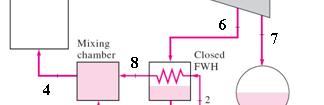
26 The closed feedwater heaters are more complex because of the internal tubing network, and thus they are more expensive. Heat transfer in closed feedwater heaters is less effective since the two streams are not allowed to be in direct contact. However, closed feedwater heaters do not require a separate pump for each heater since the extracted steam and the feedwater can be at different pressures. A steam power plant with one open and three closed feedwater heaters. The condensed steam is then either pumped p to the feedwater line or routed to another heater or to the condenser through a device called a trap. A trap allows the liquid to be throttled to a lower pressure region but traps the vapor. The enthalpy of steam remains constant during this throttling process. Open feedwater heaters are simple and inexpensive and have good heat transfer characteristics. For each heater, however, a pump is required to handle the feedwater. Most steam power plants use a combination of open and closed feedwater heaters. 26
27 EXAMPLE 10 6 The Ideal Reheat Regenerative Rankine Cycle 27
28 open fwh open fwh 28
29 29
30 EXAMPLE: A steam power plant operates on an ideal regenerative Rankine cycle. Steam enters the turbine at 6 MPa and 450 C and is condensed in the condenser at 20 kpa. Steam is extracted from the turbine at 0.4 MPa to heat the feedwater in an open feedwater heater. Water leaves the feedwater heater as a saturated liquid. Show the cycle on a T-s diagram, and determine (a) the net work output per kilogram of steam flowing through the boiler and (b) the thermal efficiency of the cycle. 30
31 31
32 32
33 x EXAMPLE: Repeat the previous example by replacing the open feedwater heater with a closed feedwater heater. Assume that the feedwater leaves the heater at the condensation temperature of the extracted steam and that the extracted steam leaves the heater as a saturated liquid and is pumped to the line carrying the feedwater. 33
34 x? 34
35 x 35
36 EXAMPLE: A steam power plant operates on an ideal reheat regenerative Rankine cycle and has a net power output of 80 MW. Steam enters the high-pressureh turbine at 10 MPa and 550 C and leaves at 0.8 MPa. Some steam is extracted at this pressure to heat the feedwater in an open feedwater heater. The rest of the steam is reheated to 500 C and is expanded in the low-pressure turbine to the condenser pressure of 10 kpa. Show the cycle on a T-s diagram with respect to saturation lines, and determine (a) the mass flow rate of steam throughh the boiler and (b) the thermal efficiency of the cycle. 36
37 SOLUTION: 37
38 38
39 10-7 SECOND-LAW ANALYSIS OF VAPOR POWER CYCLES Exergy destruction for a steady-flow system Steady-flow, oneinlet, one-exit Exergy destruction of a cycle For a cycle with heat transfer only with a source and a sink Stream exergy A second-law analysis of vaporpower cycles reveals where the largest irreversibilities occur and where to start improvements. The ideal Carnot cycle is a totally reversible cycle, and thus it does not involve any irreversibilities. The ideal Rankine cycles (simple, reheat, or regenerative), however, are only internally reversible, and they may involve irreversibilities external to the system, such as heat transfer through a finite temperature difference. A second-law analysis of these cycles reveals where the largest irreversibilities occur and what their magnitudes are. 39
40 EXAMPLE: Determine the exergy destruction associated with the reheating and regeneration processes described in previous example. Assume a source temperature of 1800 K and a sink temperature of 290 K. SOLUTION: 40

41 10-8 COGENERATION Many industries require energy input in the form of heat, called process heat. Process heat in these industries is usually supplied by steam at 5 to 7 atm and 150 to 200 C. Energy is usually transferred to the steam by burning coal, oil, natural gas, or another fuel in a furnace. Now let us examine the operation of a process-heating plant closely. Disregarding any heat losses in the piping, all the heat transferred to the steam in the boiler is used in the process-heating units, as shown in Fig Therefore, process heating seems like a perfect operation with practically no waste of energy. From the second-law point tof view, however, e,things gsdo not look soperfect. ect The etemperature peatue in furnaces is typically very high (around 1400 C), and thus the energy in the furnace is of very high quality. This high-quality energy is transferred to water to produce steam at about 200 C or below (a highly irreversible process). Associated with this irreversibility is, of course, a loss in exergy or work potential. It is simply not wise to use high-quality energy to accomplish a task that could be accomplished with low-quality energy. A simple process-heating plant. Cogeneration: The production of more than one useful form of energy (such as process heat and electric power) from the same energy source. Industries that use large amounts of process heat also consume a large amount of electric power. It makes sense to use the already-existing work potential to produce power instead of letting it go to waste. The result is a plant that produces electricity while meeting the process-heat requirements of certain industrial processes (cogeneration plant) 41


42 Utilization factor An ideal cogeneration plant. The utilization factor of the ideal steam-turbine cogeneration plant is 100%. Actual cogeneration plants have utilization factors as high as 80%. Some recent cogeneration plants have even higher utilization factors. Let us say this plant is to supply process heat Qp at 500 kpa at a rate of 100 kw. To meet this demand, steam is expanded in the turbine to a pressure of 500 kpa, producing power at a rate of, say, 20 kw. The flow rate of the steam can be adjusted such that steam leaves the processheating section as a saturated liquid at 500 kpa. Steam is then pumped to the boiler pressure and is heated in the boiler to state 3. The pump work is usually very small and can be neglected. Disregarding any heat losses, the rate of heat input in the boiler is determined from an energy balance to be 120 kw. Probably the most striking feature of the ideal steamturbine cogeneration plant shown in Fig is the absence of a condenser. Thus no heat is rejected from this plant as waste heat. In other words, all the energy transferred to the steam in the boiler is utilized as either process heat or electric power. Either a steam-turbine (Rankine) cycle or a gas-turbine (Brayton) cycle or even a combined cycle (discussed d later) can be used as the power cycle in a cogeneration plant. 42


43 A cogeneration plant with adjustable loads. Notice that without the turbine, we would need to supply heat to the steam in the boiler at a rate of only 100 kw instead of at 120 kw. The additional 20 kw of heat supplied is converted to work. Therefore, a cogeneration power plant is equivalent to a process-heating plant combined with a power plant that t has a thermal efficiency i of 100 percent. The ideal steam-turbine cogeneration plant described above is not practical because it cannot adjust to the variations in power and processheat loads. The schematic of a more practical (but more complex) cogeneration plant is shown in Fig Under normal operation, some steam is extracted from the turbine at some predetermined intermediate pressure P6. The rest of the steam expands to the condenser pressure P7 and is then cooled at constant pressure. The heat rejected from the condenser represents the waste heat for the cycle. At times of high demand for process heat, all the steam is routed to the process-heating units and none to the condenser (m7= 0). The waste heat is zero in this mode. If this is not sufficient, some steam leaving the boiler is throttled by an expansion or pressure-reducing valve (PRV) to the extraction pressure P6 and is directed to the process-heating unit. Maximum process heating is realized when all the steam leaving the boiler passes through h the PRV (m5= m4). No power is produced d in this mode. When there is no demand for process heat, all the steam passes through the turbine and the condenser (m5=m6=0), and the cogeneration plant operates as an ordinary steam power plant. The rates of heat input, heat rejected, and process heat supply as well as the power produced for this cogeneration plant can be expressed as follows: Under optimum conditions, a cogeneration plant simulates the ideal cogeneration plant discussed earlier. That is, all the steam expands in the turbine to the extraction pressure and continues to the process-heating unit. No steam passes through the PRV or the condenser; thus, no waste heat is rejected (m4 = m6 and m5=m7 = 0). This condition may be difficult to achieve in practice because of the constant variations in the process-heat and power loads. But the plant should be designed so that the optimum operating conditions are approximated most of 43 the time.
44 HINT: 1- The exit line from condenser is saturated liquid 2- The exit line from the process heater is saturated liquid 3- The exit line from Open FWH is saturated liquid 4- The exit line from Closed FWH and coming from the turbine is saturated liquid. 44


45 EXAMPLE: Steam enters the turbine of a cogeneration plant at 7 MPa and 500 C C. One-fourth of the steam is extracted from the turbine at 600- kpa pressure for process heating. The remaining steam continues to expand to 10 kpa. The extracted steam is then condensed and mixed with feedwater at constant pressure and the mixture is pumped to the boiler pressure of 7 MPa. The mass flow rate of steam through the boiler is 30 kg/s. Disregarding any pressure drops and heat losses in the piping, pp and assuming the turbine and the pump pto be isentropic, determine the net power produced and the utilization factor of the plant. 45
46 SOLUTION: 46
47 47
48 10-9 COMBINED GAS VAPOR POWER CYCLES The continued quest for higher thermal efficiencies has resulted in rather innovative modifications to conventional power plants. A popular modification involves a gas power cycle topping a vapor power cycle, which h is called the combined gas vapor cycle, or just the combined cycle. The combined cycle of greatest interest is the gas-turbine (Brayton) cycle topping a steam-turbine (Rankine) cycle, which has a higher thermal efficiency than either of the cycles executed individually. It makes engineering sense to take advantage of the very desirable characteristics of the gas-turbine cycle at high temperatures and to use the hightemperature exhaust gases as the energy source for the bottoming cycle such as a steam power cycle. The result is a combined gas steam cycle. Recent developments in gas-turbine technology have made the combined gas steam cycle economically very attractive. The combined cycle increases the efficiency without increasing the initial cost greatly. Consequently, many new power plants operate on combined cycles, and many more existing steam- or gas-turbine plants are being converted to combined-cycle power plants. Thermal efficiencies over 50% are reported. 48
49 Gas-turbine cycles typically operate at considerably higher temperatures than steam cycles. The maximum fluid temperature at the turbine inlet is about 620 C (1150 F) for modern steam power plants, but over 1425 C (2600 F) for gas-turbine power plants. It is over 1500 C at the burner exit of fturbojet tengines. The use of fhigher h temperatures t in gas turbines is made possible by recent developments in cooling the turbine blades and coating the blades with high-temperature-resistant materials such as ceramics. The energy source of the steam is the waste energy of the exhausted combustion gases. heat exchanger serves as the boiler. Combined gas steam power plant. 49
50 EXAMPLE: The gas-turbine portion of a combined gas steam power plant has a pressure ratio of 16. Air enters the compressor at 300 K at a rate of 14 kg/s and is heated to 1500 K in the combustion chamber. The combustion gases leaving the gas turbine are used to heat the steam to 400 C at 10 MPa in a heat exchanger. The combustion gases leave the heat exchanger at 420 K. The steam leaving the turbine is condensed at 15 kpa. Assuming all the compression and expansion processes to be isentropic, determine (a) the mass flow rate of the steam, (b) the net power output, and (c) The thermal efficiency of the combined cycle. For air, assume constant specific heats at room temp. 50
51 SOLUTION: 51
52 52
53 Summary The Carnot vapor cycle Rankine cycle: The ideal cycle for vapor power cycles Energy analysis of the ideal Rankine cycle Deviation of actual vapor power cycles from idealized ones How can we increase the efficiency of the Rankine cycle? Lowering the condenser pressure (Lowers T low,avg ) Superheating the steam to high temperatures (Increases T high,avg ) Increasing the boiler pressure (Increases T high,avg ) The ideal reheat Rankine cycle The ideal regenerative Rankine cycle Open feedwater heaters Closed feedwater heaters Second-law analysis of vapor power cycles Cogeneration Combined gas vapor power cycles 53
Chapter 10 VAPOR AND COMBINED POWER CYCLES
 Thermodynamics: An Engineering Approach, 6 th Edition Yunus A. Cengel, Michael A. Boles McGraw-Hill, 2008 Chapter 10 VAPOR AND COMBINED POWER CYCLES Copyright The McGraw-Hill Companies, Inc. Permission
Chapter 10. In Chap. 9 we discussed gas power cycles for which the VAPOR AND COMBINED POWER CYCLES. Objectives
 Chapter 0 VAPOR AND COMBINED POWER CYCLES In Chap. 9 we discussed gas power cycles for which the working fluid remains a gas throughout the entire cycle. In this chapter, we consider vapor power cycles
Vapor and Combined Power Cycles
 9 CHAPTER Vapor and Combined Power Cycles 9-1 The Simple Ideal Rankine Cycle The 9-2 Rankine Cycle: Actual Vapor Power Deviation and Pump and Turbine Irreversibilities (a) Deviation of actual vapor power
Chapter 1 STEAM CYCLES
 Chapter 1 STEAM CYCLES Assoc. Prof. Dr. Mazlan Abdul Wahid Faculty of Mechanical Engineering Universiti Teknologi Malaysia www.fkm.utm.my/~mazlan 1 Chapter 1 STEAM CYCLES 1 Chapter Objectives To carry
Lecture No.1. Vapour Power Cycles
 Lecture No.1 1.1 INTRODUCTION Thermodynamic cycles can be primarily classified based on their utility such as for power generation, refrigeration etc. Based on this thermodynamic cycles can be categorized
water is typically used as the working fluid because of its low cost and relatively large value of enthalpy of vaporization
 Rankine Cycle Reading Problems 10-2 10-7 10-16, 10-34, 10-37, 10-44, 10-47, 10-59 Definitions working fluid is alternately vaporized and condensed as it recirculates in a closed cycle water is typically
Consider a simple ideal Rankine cycle with fixed turbine inlet conditions. What is the effect of lowering the condenser pressure on
 Chapter 10, Problem 8C. Consider a simple ideal Rankine cycle with fixed turbine inlet conditions. What is the effect of lowering the condenser pressure on Pump work input: Turbine work output: Heat supplied:
CHAPTER 1 BASIC CONCEPTS
 GTU Paper Analysis CHAPTER 1 BASIC CONCEPTS Sr. No. Questions Jan 15 Jun 15 Dec 15 May 16 Jan 17 Jun 17 Nov 17 May 18 Differentiate between the followings; 1) Intensive properties and extensive properties,
Reading Problems , 11.36, 11.43, 11.47, 11.52, 11.55, 11.58, 11.74
 Rankine Cycle Reading Problems 11.1 11.7 11.29, 11.36, 11.43, 11.47, 11.52, 11.55, 11.58, 11.74 Definitions working fluid is alternately vaporized and condensed as it recirculates in a closed cycle the
Chapter 10 Vapor and Combined Power Cycles
 Chapter 10 Vapor and Combined Power Cycles Dr. Mohammad Tarawneh Thermodynamics: An Engineering Approach, 5th edition by Yunus A. Çengel and Michael A. Boles We consider power cycles where the working
Faculty of Engineering 2 nd year 2016 Mechanical Engineering Dep. Final-exam (code: M 1222)
") Benha University Thermodynamics II Faculty of Engineering 2 nd year 2016 Mechanical Engineering Dep. Final-exam (code: M 1222) Time: Three Hours (attempt all questions) (assume any missing data) Question1
Benha University Thermodynamics II Faculty of Engineering 2 nd year 2016 Mechanical Engineering Dep. Final-exam (code: M 1222) Time: Three Hours (attempt all questions) (assume any missing data) Question1
Chapter 9: Vapor Power Systems
 Chapter 9: Vapor Power Systems Table of Contents Introduction... 2 Analyzing the Rankine Cycle... 4 Rankine Cycle Performance Parameters... 5 Ideal Rankine Cycle... 6 Example... 7 Rankine Cycle Including
Chapter 8. Vapor Power Systems
 Chapter 8 Vapor Power Systems Introducing Power Generation To meet our national power needs there are challenges related to Declining economically recoverable supplies of nonrenewable energy resources.
Practice Final Exam (A) Six problems. (Open-book, HW solutions, and notes) (Plus /minus 10 % error acceptable for all numerical answers)
 Six problems. (Open-book, HW solutions, and notes) (Plus /minus 10 % error acceptable for all numerical answers)") ME 3610 Practice Final Exam (A) Six problems. (Open-book, HW solutions, and notes) (Plus /minus 10 % error acceptable for all numerical answers) (18 points) 1. A gasoline engine operating on the ideal
ME 3610 Practice Final Exam (A) Six problems. (Open-book, HW solutions, and notes) (Plus /minus 10 % error acceptable for all numerical answers) (18 points) 1. A gasoline engine operating on the ideal
ME ENGINEERING THERMODYNAMICS UNIT III QUESTION BANK SVCET
 1. A vessel of volume 0.04m 3 contains a mixture of saturated water and steam at a temperature of 250 0 C. The mass of the liquid present is 9 kg. Find the pressure, mass, specific volume, enthalpy, entropy
Problems in chapter 9 CB Thermodynamics
 Problems in chapter 9 CB Thermodynamics 9-82 Air is used as the working fluid in a simple ideal Brayton cycle that has a pressure ratio of 12, a compressor inlet temperature of 300 K, and a turbine inlet
Feedwater Heaters (FWH)
") Feedwater Heaters (FWH) A practical Regeneration process in steam power plants is accomplished by extracting or bleeding, steam from the turbine at various points. This steam, which could have produced
Feedwater Heaters (FWH) A practical Regeneration process in steam power plants is accomplished by extracting or bleeding, steam from the turbine at various points. This steam, which could have produced
a. The power required to drive the compressor; b. The inlet and output pipe cross-sectional area. [Ans: kw, m 2 ] [3.34, R. K.
![a. The power required to drive the compressor; b. The inlet and output pipe cross-sectional area. [Ans: kw, m 2 ] [3.34, R. K.](/thumbs/76/73432086.jpg "a. The power required to drive the compressor; b. The inlet and output pipe cross-sectional area. [Ans: kw, m 2 ] [3.34, R. K.") CHAPTER 2 - FIRST LAW OF THERMODYNAMICS 1. At the inlet to a certain nozzle the enthalpy of fluid passing is 2800 kj/kg, and the velocity is 50 m/s. At the discharge end the enthalpy is 2600 kj/kg. The
CHAPTER 2 - FIRST LAW OF THERMODYNAMICS 1. At the inlet to a certain nozzle the enthalpy of fluid passing is 2800 kj/kg, and the velocity is 50 m/s. At the discharge end the enthalpy is 2600 kj/kg. The
2. The data at inlet and exit of the turbine, running under steady flow, is given below.
 3 rd week quiz 1. Identify the correct path of fluid flow in a steam power plant. a) Steam turbine-pump-boiler-condenser. b) Economizer- evaporator- superheater. c) Pump-turbine-condenser-evaporator. d)
Stationary Combustion Systems Chapter 6
 Stationary Combustion Systems Chapter 6 Stationary combustion systems presently supply most of the earth s electricity. Conversion will take time, so study of these systems in order to improve them is
Lecture No.3. The Ideal Reheat Rankine Cycle
 Lecture No.3 The Ideal Reheat Rankine Cycle 3.1 Introduction We noted in the last section that increasing the boiler pressure increases the thermal efficiency of the Rankine cycle, but it also increases
Second Law of Thermodynamics
 Second Law of Thermodynamics Content Heat engine and its efficiency. Reversible and irreversible processes. The Carnot machine. Kelvin Planck Statement. Refrigerator and Coefficient of Performance. Statement
Chapter Two. The Rankine cycle. Prepared by Dr. Shatha Ammourah
 Chapter Two The Rankine cycle Prepared by Dr. Shatha Ammourah 1 The Ideal Rankine Cycle Schematic Diagram of ideal simple Rankine 2 Superheater Economizer line 3 Heat Addition Types In The Steam Generator
Eng Thermodynamics I - Examples 1
 Eng3901 - Thermodynamics I - Examples 1 1 pdv Work 1. Air is contained in a vertical frictionless piston-cylinder. The mass of the piston is 500 kg. The area of the piston is 0.005 m 2. The air initially
Rankine cycle. Contents. Description
 Page 1 of 7 Rankine cycle From Wikipedia, the free encyclopedia The Rankine cycle is a model that is used to predict the performance of steam turbine systems. The Rankine cycle is an idealized thermodynamic
Eng Thermodynamics I - Examples 1
 Eng3901 - Thermodynamics I - Examples 1 1 pdv Work 1. Air is contained in a vertical frictionless piston-cylinder. The mass of the piston is 500 kg. The area of the piston is 0.005 m 2. The air initially
- 2 - SME Q1. (a) Briefly explain how the following methods used in a gas-turbine power plant increase the thermal efficiency:
 Briefly explain how the following methods used in a gas-turbine power plant increase the thermal efficiency:") - 2 - Q1. (a) Briefly explain how the following methods used in a gas-turbine power plant increase the thermal efficiency: i) regenerator ii) intercooling between compressors (6 marks) (b) Air enters a
- 2 - Q1. (a) Briefly explain how the following methods used in a gas-turbine power plant increase the thermal efficiency: i) regenerator ii) intercooling between compressors (6 marks) (b) Air enters a
Chapters 5, 6, and 7. Use T 0 = 20 C and p 0 = 100 kpa and constant specific heats unless otherwise noted. Note also that 1 bar = 100 kpa.
 Chapters 5, 6, and 7 Use T 0 = 20 C and p 0 = 100 kpa and constant specific heats unless otherwise noted. Note also that 1 bar = 100 kpa. 5-1. Steam enters a steady-flow device at 16 MPa and 560 C with
OUTCOME 2 TUTORIAL 2 STEADY FLOW PLANT
 UNIT 47: Engineering Plant Technology Unit code: F/601/1433 QCF level: 5 Credit value: 15 OUTCOME 2 TUTORIAL 2 STEADY FLOW PLANT 2 Be able to apply the steady flow energy equation (SFEE) to plant and equipment
2291-6A. Joint ICTP-IAEA Course on Science and Technology of Supercritical Water Cooled Reactors. 27 June - 1 July, 2011
 2291-6A Joint ICTP-IAEA Course on Science and Technology of Supercritical Water Cooled Reactors 27 June - 1 July, 2011 INTRODUCTION TO THERMODYNAMICS Igor PIORO Faculty of Energy Systems and Nuclear Science
R13. II B. Tech I Semester Regular/Supplementary Examinations, Oct/Nov THERMODYNAMICS (Com. to ME, AE, AME) Time: 3 hours Max.
 Time: 3 hours Max.") SET - 1 1. a) Discuss about PMM I and PMM II b) Explain about Quasi static process. c) Show that the COP of a heat pump is greater than the COP of a refrigerator by unity. d) What is steam quality? What
SET - 1 1. a) Discuss about PMM I and PMM II b) Explain about Quasi static process. c) Show that the COP of a heat pump is greater than the COP of a refrigerator by unity. d) What is steam quality? What
A. the temperature of the steam at the turbine exhaust increases. B. additional moisture is removed from the steam entering the turbine.
 P77 Overall nuclear power plant thermal efficiency will decrease if... A. the temperature of the steam at the turbine exhaust increases. B. additional moisture is removed from the steam entering the turbine.
Chapter 6: Stationary Combustion Systems
 Chapter 6: Stationary Combustion Systems Figure 6-1. Schematic of components of coal-fired electric plant, with conversion of coal to electricity via boiler, turbine, and generator US Energy Sources 2004
Problems 2-9 are worth 2 points each. Circle T or F as appropriate for problems 6-9.
 NAME KEY Allowed: Writing utensil, calculator and the provided formula sheet. Books, notes and collaboration (friends) are not allowed! Clearly indicate your answer and show your work. I do give partial
FEE, CTU in Prague Power Engineering 2 (BE5B15EN2) Exercise 3
 Exercise 3") Example 1: How is the applied heat for 1 kg of water steam at constant pressure p = 1.47 MPa, if the dryness of wet water is increased from x 1 = 0.8 to x 2 = 0.96? Dryness of wet steam the ratio of steam
Example 1: How is the applied heat for 1 kg of water steam at constant pressure p = 1.47 MPa, if the dryness of wet water is increased from x 1 = 0.8 to x 2 = 0.96? Dryness of wet steam the ratio of steam
Chapter 1 Basic Concepts
 Jan 15 Jun 15 Chapter 1 Basic Concepts GTU Paper Analysis (New Syllabus) Sr. No. Questions Differentiate between the followings; 1) Intensive properties and extensive properties, 2) Point function and
CHAPTER 1 BASIC CONCEPTS THEORY
 CHAPTER 1 BASIC CONCEPTS THEORY 1. Explain briefly the following terms with diagram (wherever necessary): a) Thermodynamic System, Surroundings & Boundary b) Control Volume & Control Surface c) Intensive
Overall nuclear power plant thermal efficiency will decrease if... A. the temperature of the steam at the turbine exhaust increases.
 P77 Overall nuclear power plant thermal efficiency will decrease if... A. the temperature of the steam at the turbine exhaust increases. B. additional moisture is removed from the steam entering the turbine.
Power cycles. Principles of combustion cycles and efficient concepts
 Power cycles Principles of combustion cycles and efficient concepts This contribution is based on the EC BREF- document Reference Document on Best Available Techniques for Large Combustion Plants July
Introduction to Aerospace Propulsion. Prof. Bhaskar Roy. Prof. A. M. Pradeep. Department of Aerospace Engineering
 Introduction to Aerospace Propulsion Prof. Bhaskar Roy Prof. A. M. Pradeep Department of Aerospace Engineering Indian Institute of technology, Bombay Module No. # 01 Lecture No. # 18 Rankine cycle, Brayton
AREN 2110: Thermodynamics Spring 2010 Homework 7: Due Friday, March 12, 6 PM
 AREN 2110: Thermodynamics Spring 2010 Homework 7: Due Friday, March 12, 6 PM 1. Answer the following by circling the BEST answer. 1) The boundary work associated with a constant volume process is always
MECHANICAL ENGINEERING DEPARTMENT, OITM
 Sem.:4 th Subject: Energy Conversion Paper: ME-201E UNIT-1 Q1. Explain the seismometer with its working principle. (Important Question) (20) Q2. Classify the fuels and define calorific value of fuels.
SHRI RAMSWAROOP MEMORIAL COLLEGE OF ENGG. & MANAGEMENT B.Tech. [SEM IV (ME-41, 42,43 & 44)] QUIZ TEST-1 (Session: )
![SHRI RAMSWAROOP MEMORIAL COLLEGE OF ENGG. & MANAGEMENT B.Tech. [SEM IV (ME-41, 42,43 & 44)] QUIZ TEST-1 (Session: )](/thumbs/72/67555697.jpg "SHRI RAMSWAROOP MEMORIAL COLLEGE OF ENGG. & MANAGEMENT B.Tech. [SEM IV (ME-41, 42,43 & 44)] QUIZ TEST-1 (Session: )") QUIZ TEST-1 Q.1. In a stage of an impulse turbine provided with a single row wheel, the mean diameter of the blade ring is 80cm and the speed of the rotation is 3000rpm. The steam issues from the nozzle
QUIZ TEST-1 Q.1. In a stage of an impulse turbine provided with a single row wheel, the mean diameter of the blade ring is 80cm and the speed of the rotation is 3000rpm. The steam issues from the nozzle
Efficiency improvement of steam power plants in Kuwait
 Energy and Sustainability V 173 Efficiency improvement of steam power plants in Kuwait H. Hussain, M. Sebzali & B. Ameer Energy and Building Research Center, Kuwait Institute for Scientific Research, Kuwait
EXTRA CREDIT OPPORTUNITY: Due end of day, Thursday, Dec. 14
 EXRA CREDI OPPORUNIY: Due end of day, hursday, Dec. 4 his extra credit set of questions is an opportunity to improve your test scores (including an insurance policy for your final exam grade). here are
Eng Thermodynamics I: Sample Final Exam Questions 1
 Eng3901 - Thermodynamics I: Sample Final Exam Questions 1 The final exam in Eng3901 - Thermodynamics I consists of four questions: (1) 1st Law analysis of a steam power cycle, or a vapour compression refrigeration
Applied Thermo Fluids-II: (Autumn 2017) Section-A: Thermal Power Plants
 Section-A: Thermal Power Plants") Applied Thermo Fluids-II: (Autumn 2017) Section-A: Thermal Power Plants Module-1 (Introduction & Thermodynamics of thermal power plants) Dr. M. Ramgopal, Mechanical Engineering, IIT Kharagpur Reference:
Applied Thermo Fluids-II: (Autumn 2017) Section-A: Thermal Power Plants Module-1 (Introduction & Thermodynamics of thermal power plants) Dr. M. Ramgopal, Mechanical Engineering, IIT Kharagpur Reference:
Exergy in Processes. Flows and Destruction of Exergy
 Exergy in Processes Flows and Destruction of Exergy Exergy of Different Forms of Energy Chemical Energy Heat Energy Pressurised Gas Electricity Kinetic Energy Oxidation of Methane ΔH = -890.1 kj/mol ΔS
Rankine cycle. Contents. Description
 페이지 1 / 6 Rankine cycle From Wikipedia, the free encyclopedia The Rankine cycle is a cycle that converts heat into work. The heat is supplied externally to a closed loop, which usually uses water. This
Design Features of Combined Cycle Systems
 Design Features of Combined Cycle Systems 1.0 Introduction As we have discussed in class, one of the largest irreversibilities associated with simple gas turbine cycles is the high temperature exhaust.
Methods of increasing thermal efficiency of steam and gas turbine plants
 Journal of Physics: Conference Series PAPER OPEN ACCESS Methods of increasing thermal efficiency of steam and gas turbine plants To cite this article: A A Vasserman and M A Shutenko 2017 J. Phys.: Conf.
CHAPTER 2 STUDY OF 210 MW BOILER SYSTEM 2.1 DESCRIPTION OF 210 MW BOILER
 8 CHAPTER 2 STUDY OF 210 MW BOILER SYSTEM 2.1 DESCRIPTION OF 210 MW BOILER Detailed study has been carried out on a 210 MW boiler system with regard to model development, control and optimization. Figure
LECTURE-14. Air Refrigeration Cycles. Coefficient of Performance of a Refrigerator:
 Lecturer: -Dr. Esam Mejbil Abid Subject: Air Conditioning and Refrigeration Year: Fourth B.Sc. Babylon University College of Engineering Department of Mechanical Engineering LECTURE-14 Air Refrigeration
CHAPTER 2 POWER PLANT THERMODYNAMICS
 CHAPTER 2 POWER PLANT THERMODYNAMICS 2.1. Thermodynamic Prciples... 2 2.2. Steady Flow Engeerg Devices and Processes... 4 2.3. Heat Enge and Cycles... 8 2.4. Carnot Cycle... 10 2.5. Ranke Cycle... 10 Chapter
Performance Benefits for Organic Rankine Cycles with Flooded Expansion
 Purdue University Purdue e-pubs Publications of the Ray W. Herrick Laboratories School of Mechanical Engineering 6-2-2010 Performance Benefits for Organic Rankine Cycles with Flooded Expansion Brandon
CH 7: GAS-TURBINE ENGINES Prepared by Dr. Assim Al-Daraje BRAYTON CYCLE: THE IDEAL CYCLE FOR GAS-TURBINE ENGINES
 CH 7: GAS-TURBINE ENGINES Prepared by Dr. Assim Al-Daraje BRAYTON CYCLE: THE IDEAL CYCLE FOR GAS-TURBINE ENGINES The combustion process is replaced by a constant-pressure heat-addition process from an
UNIVERSITY OF TORONTO FACULTY OF APPLIED SCIENCE AND ENGINEERING FINAL EXAMINATION, DECEMBER 2008 MIE 411H1 F - THERMAL ENERGY CONVERSION
 UNIVERSITY OF TORONTO FACULTY OF APPLIED SCIENCE AND ENGINEERING FINAL EXAMINATION, DECEMBER 2008 MIE 411H1 F - THERMAL ENERGY CONVERSION Exam Type: X Examiner: J.S. Wallace You may use your copy of the
ANALYSIS OF DIFFERENT TYPES OF REGULATION AND ITS EFFICIENCY IN STEAM POWER CYCLES MASTER THESIS
 ANALYSIS OF DIFFERENT TYPES OF REGULATION AND ITS EFFICIENCY IN STEAM POWER CYCLES MASTER THESIS Author: Ricardo Sánchez Pereiro Advisor: Piotr Krzyslak Poznan University of Technology 11/06/2012 INDEX
Improvement of distillation column efficiency by integration with organic Rankine power generation cycle. Introduction
 Improvement of distillation column efficiency by integration with organic Rankine power generation cycle Dmitriy A. Sladkovskiy, St.Petersburg State Institute of Technology (technical university), Saint-
HW-1: Due Tuesday 13 Jun 2017 by 2:00:00 pm EDT to Your Division s GradeScope Site
 HW-1: Due Tuesday 13 Jun 2017 by 2:00:00 pm EDT to A residential ceiling fan is shown in the photograph below. It consists of an electric motor, the fan blades, and the light. Sketch each of these three
( h) ( ) Effect of Boiler Pressure (Using Molliar Diagram i.e., h-s diagram) We have, but W P << W T. = = h h h h
 ( ) Effect of Boiler Pressure (Using Molliar Diagram i.e., h-s diagram) We have, but W P << W T. = = h h h h") Effect of Boiler Pressure (Using Molliar Diagram i.e., -s diagram) We ave, ( 3 ) ( 4 ) η t but W P P > P for te fixed
Effect of Boiler Pressure (Using Molliar Diagram i.e., -s diagram) We ave, ( 3 ) ( 4 ) η t but W P P > P for te fixed
PI Heat and Thermodynamics - Course PI 25 CRITERION TEST. of each of the following a. it
 Heat and Thermodynamics - Course PI 25 CRITERION TESTS PI 25-1 - 1. Define: heat temperature (c) enthalpy 2. State the applies to meaning water: of each of the following a. it saturation temperature subcooled
External and Internal Irreversibility
 External and Internal Irreversibility Heat Engine as an Example Arnab Sarkar and S S Mondal The article attempts to clarify the meaning of internal and external irreversibility using the example of a heat
Secondary Systems: Steam System
 Secondary Systems: Steam System K.S. Rajan Professor, School of Chemical & Biotechnology SASTRA University Joint Initiative of IITs and IISc Funded by MHRD Page 1 of 10 Table of Contents 1 SECONDARY SYSTEM
Reg. No. : Question Paper Code : B.E./B.Tech. DEGREE EXAMINATION, NOVEMBER/DECEMBER Second Semester
 ws15 Reg. No. : Question Paper Code : 27425 B.E./B.Tech. DEGREE EXAMINATION, NOVEMBER/DECEMBER 2015. Time : Three hours Second Semester Marine Engineering MV 6201 MARINE ENGINEERING THERMODYNAMICS (Regulations
MODELING THERMODYNAMIC ANALYSIS AND SIMULATION OF ORGANIC RANKINE CYCLE USING GEOTHERMAL ENERGY AS HEAT SOURCE
 MODELING THERMODYNAMIC ANALYSIS AND SIMULATION OF ORGANIC RANKINE CYCLE USING GEOTHERMAL ENERGY AS HEAT SOURCE Colak L.* and Bahadir T. *Author for correspondence Department of Mechanical Engineering,
CHAPTER 5 MASS AND ENERGY ANALYSIS OF CONTROL VOLUMES
 Thermodynamics: An Engineering Approach 8th Edition in SI Units Yunus A. Ç engel, Michael A. Boles McGraw-Hill, 2015 CHAPTER 5 MASS AND ENERGY ANALYSIS OF CONTROL VOLUMES Objectives Develop the conservation
MCG THERMODYNAMICS II. 22 April 2008 Page 1 of 7 Prof. W. Hallett
 Faculté de génie Génie mécanique Faculty of Engineering Mechanical Engineering MCG2131 - THERMODYNAMICS II 22 April 2008 Page 1 of 7 Prof. W. Hallett Closed book. Non-programmable calculators only allowed.
Chapter 5: Thermodynamic Processes and Cycles
 Chapter 5: Thermodynamic Processes and Cycles 5-6) This problem examines the Rankine heat engine introduced in Figure 5-5. Saturated steam at T = 250 C enters the turbine and the condenser operates at
R13 SET - 1 '' ''' '' ' '''' Code No: RT31035
 R13 SET - 1 III B. Tech I Semester Regular/Supplementary Examinations, October/November - 2016 THERMAL ENGINEERING II (Mechanical Engineering) Time: 3 hours Max. Marks: 70 Note: 1. Question Paper consists
Dr. S.Ramachandran, M.E., Ph.D., Professor and Research Head Faculty of Mechanical Engineering
 (For BE Mechanical Engineering Students) (As per New Syllabus of Leading Universities) Dr SRamachandran, ME, PhD, Professor and Research Head Faculty of Mechanical Engineering SATHYABAMA UNIVERSITY Jeppiaar
Engineering Thermodynamics
 Unit 61: Engineering Thermodynamics Unit code: D/601/1410 QCF level: 5 Credit value: 15 Aim This unit will extend learners knowledge of heat and work transfer. It will develop learners understanding of
wb Thermodynamics 2 Lecture 10 Energy Conversion Systems
 wb1224 - Thermodynamics 2 Lecture 10 Energy Conversion Systems Piero Colonna, Lecturer Prepared with the help of Teus van der Stelt 13-12-2010 Delft University of Technology Challenge the future Content
Review Questions for the FE Examination
 110 THE FIRST LAW OF THERMODYNAMICS [CHAP. 4 4.1FE Review Questions for the FE Examination Select a correct statement of the first law if kinetic and potential energy changes are negligible. (A) Heat transfer
ESO 201A Thermodynamics
 ESO 201A Thermodynamics Instructor: Sameer Khandekar Tutorial 10 [8-23] A house that is losing heat at a rate of 50,000 kj/h when the outside temperature drops to 4 C is to be heated byelectric resistance
Combined Heat and Power
 Lecture 12 Combined Heat and Power Combustion Turbines and Co-generation Combustion Turbines and Combined Heat and Power (CHP) Systems See B. K. Hodge, Chapter 5 and Chapter 11. ISBN: 978-0-470-14250-9
Fundamental Investigation Of Whole-Life Power Plant Performance For Enhanced Geothermal Systems
 Purdue University Purdue e-pubs International Refrigeration and Air Conditioning Conference School of Mechanical Engineering 2016 Fundamental Investigation Of Whole-Life Power Plant Performance For Enhanced
PEMP RMD & Cycle Performance. M.S.Ramaiah School of Advanced Studies
 Steam Se Turbine ub ecyces Cycles & Cycle Performance Session delivered by: Prof. Q.H. Nagpurwala 1 Session Objectives This session is intended to discuss the following: Basic construction and classification
MEM 310 Design Project Assignment
 MEM 310 Design Project Assignment Prepared by Bradley R. Schaffer Drexel University Philadelphia, PA 19104 Submitted to: Dr. William J. Danley of MEM 310 - Thermodynamic Analysis I on May 28, 2004 Abstract
COMPARATIVE ANALYSES OF TWO IMPROVED CO 2 COMBINED COOLING, HEATING, AND POWER SYSTEMS DRIVEN BY SOLAR ENERGY
 S93 Introduction COMPARATIVE ANALYSES OF TWO IMPROVED CO 2 COMBINED COOLING, HEATING, AND POWER SYSTEMS DRIVEN BY SOLAR ENERGY by Wanjin BAI a* and Xiaoxiao XU b a School of Mechanical and Vehicle Engineering,
PERFORMANCE ANALYSIS OF REHEATED GAS TURBINE BASED POWER PLANT CYCLE
 PERFORMANCE ANALYSIS OF REHEATED GAS TURBINE BASED POWER PLANT CYCLE Mithilesh Kumar Sahu 1, Shivam Mishra 2 1 Ph.D. Scholar, Mechanical Engg. Department, NIT, Jamshedpur, INDIA 2 Ph.D. Scholar, Mechanical
S.E. (Mechanical) (First Semester) EXAMINATION, 2012 APPLIED THERMODYNAMICS (2008 PATTERN) Time : Three Hours Maximum Marks : 100
 (First Semester) EXAMINATION, 2012 APPLIED THERMODYNAMICS (2008 PATTERN) Time : Three Hours Maximum Marks : 100") Total No. of Questions 12] [Total No. of Printed Pages 8 Seat No. [4162]-111 S.E. (Mechanical) (First Semester) EXAMINATION, 2012 APPLIED THERMODYNAMICS (2008 PATTERN) Time : Three Hours Maximum Marks
Total No. of Questions 12] [Total No. of Printed Pages 8 Seat No. [4162]-111 S.E. (Mechanical) (First Semester) EXAMINATION, 2012 APPLIED THERMODYNAMICS (2008 PATTERN) Time : Three Hours Maximum Marks
Code No: RR Set No. 1
 Code No: RR310303 Set No. 1 III B.Tech I Semester Regular Examinations, November 2006 THERMAL ENGINEERING-II (Mechanical Engineering) Time: 3 hours Max Marks: 80 Answer any FIVE Questions All Questions
IJSRD - International Journal for Scientific Research & Development Vol. 4, Issue 06, 2016 ISSN (online):
:") IJSRD - International Journal for Scientific Research & Development Vol. 4, Issue 06, 016 ISSN (online): 31-0613 Thermodynamic Analysis of Thermal Power Plant Cycle Veeranagouda Patil 1 M. R. Nagaraj 1
IJSRD - International Journal for Scientific Research & Development Vol. 4, Issue 06, 016 ISSN (online): 31-0613 Thermodynamic Analysis of Thermal Power Plant Cycle Veeranagouda Patil 1 M. R. Nagaraj 1
Optimization of operating parameters for a 600MW Rankine cycle based Ultra Supercritical power plant
 Optimization of operating parameters for a 600MW Rankine cycle based Ultra Supercritical power plant Peyyala Nagasubba Rayudu 1, Dr. K. GovindaRajulu 2 1 Research Scholar, Dept. of ME, JNTUA, Anantapuramu
Application of Exergy Analysis. Value and Limitations
 Application of Exergy Analysis Value and Limitations Power Plant Exergy Flows and Destruction Stack 2 Other Losses 1 Fuel 92 27 65 20 Steam 43 7 Shaft Power 32 Combustion Heat Transfer Turbine Steam 3
THERMAL AND HYDRAULIC MACHINES UNIT 2
 THERMAL AND HYDRAULIC MACHINES UNIT 2 A steam turbine is a device that extracts thermal energy from pressurized steam and uses it to do mechanical work on a rotating output shaft. Its modern manifestation
Ms.P.Aileen Sonia Dhas
 SUBJECT CODE SUBJECT NAME STAFF NAME : ME8792 : Power Plant Engineering : Prof.V.Tamil Selvi Ms.P.Aileen Sonia Dhas UNIT- I COAL BASED THERMAL POWER PLANTS Rankine cycle - improvisations, Layout of modern
Thermodynamics: An Engineering Approach, 6 th Edition Yunus A. Cengel, Michael A. Boles McGraw-Hill, 2008
 Thermodynamics: An Engineering Approach, 6 th Edition Yunus A. Cengel, Michael A. Boles McGraw-Hill, 2008 Chapter 5 MASS AND ENERGY ANALYSIS OF CONTROL VOLUMES SUMMARY 1 CONSERVATION OF MASS Conservation
Thermoelectric Design
 INTERAMERICAN UNIVERSITY OF BAYAMON PUERTO RICO Thermoelectric Design Thermodynamic 2 Erik T. Rosado Rolando Santiago 5/15/2012 TABLE OF CONTENTS TABLE OF FIGURE... 2 TABLE OF DATA RESULTS... 2 ABSTRACT...
Actual Gas-Turbine Cycle
 Actual Gas-urbine Cycle Fresh air at ambient conditions is drawn into the compressor, where its temperature and pressure are raised. he highpressure air proceeds into the combustion chamber, where the
Written Exam 02 March Problems - Time: 2 hours PLEASE NOTICE
 Politecnico di Milano Department of Energy - School of Industrial Engineering Course Energy Systems LM prof. S. Consonni, E. Martelli, M. Romano - Academic Year 2014/15 Written Exam 02 March 2015 - Problems
MUZAFFARPUR INSTITUTE OF TECHNOLOGY COURSE FILE OF THERMODYNAMICS FACULTY NAME: AMIT KUMAR ASSISTANT PROFESSOR DEPARTMENT OF MECHANICAL ENGINEERING
 MUZAFFARPUR INSTITUTE OF TECHNOLOGY COURSE FILE OF THERMODYNAMICS FACULTY NAME: AMIT KUMAR ASSISTANT PROFESSOR DEPARTMENT OF MECHANICAL ENGINEERING CONTENTS 1. Cover Page& Content 2. Vision of the Department
MCE535 Thermal Power and Propulsive Systems. Lecture 04: 04/10/2017
 MCE535 Thermal Power and Propulsive Systems Lecture 04: 04/10/2017 Dr. Ayokunle O. Balogun (A212) balogun.ayokunle@lmu.edu.ng Class: Thursday (3 5 pm) Etiquettes and MOP Attendance is a requirement. There
Utilization of THERMOPTIM Optimization Method
 Utilization of THERMOPTIM Optimization Method Thermoptim optimization method is dedicated to complex systems where a large number of fluids exchange heat, the overall behaviour of the system being governed
Superior Efficiency Reduced Costs Viable Alternative Energy Kalex Kalina Cycle Power Systems For Biomass Applications
 Superior Efficiency Reduced Costs Viable Alternative Energy Kalex Kalina Cycle Power Systems For Biomass Applications Copyright 2009, 2010, Kalex LLC. Kalex LLC's Kalina Cycle for Biomass Applications
ASSIGNMENT 2 Coal and Ash Handling System and Draught Systems
 ASSIGNMENT 1 Thermal Power Plant & High Pressure Boiler 1. State the factors to be considered for selection of site for thermal power plant 2. State desirable to control the super heat temperature. Explain