Air Conditioners Technical Data
|
|
|
- William Thornton
- 5 years ago
- Views:
Transcription


1 Air Conditioners Technical Data O u t d o o r U n i t E E D E N RX-GV
2 Outdoor Unit RX-GV TABLE OF CONTENTS RX-GV Features Specifications Nominal Capacity And Nominal Input Technical Specifications Electrical Specifications Electrical data Electrical Data Capacity tables Cooling/Heating Capacity Tables Dimensional drawings Dimensional Drawings Centre of gravity Centre of Gravity Piping diagrams Piping Diagrams Wiring diagrams Wiring Diagrams - Single Phase Sound data Sound Pressure Spectrum Operation range Operation Range Split - Sky Air Outdoor Unit

3 k i n - r o t o i d l t - pu Outdoor Unit RX-GV Features S U V G X SO R Outdoor units for pair application Energy efficient units: full range A class energy labels Outdoor unit silent operation: "silent" button on the remote control lowers the operation sound of the outdoor unit by 3dBA to ensure a quiet environment for the neighbourhood. Daikin outdoor units are neat, sturdy and can easily be mounted on a roof or terrace or simply placed against an outside wall Energy saving during standby mode: reduces current consumption by about 80% when operating In standby. If no people are detected for more than 20 minutes, the system will automatically switch to the current-saving mode. Outdoor units are fitted with a swing compressor, renowned for its low noise and high energy efficiency 2 Split - Sky Air Outdoor Unit
4 2 Specifications Outdoor Unit RX-GV 2- Nominal Capacity And Nominal Input FTX50GV/RX50GV FTX60GV/RX60GV FTX7GV/RX7GV Cooling capacity Min. kw Btu/h 5,800 7,800 kcal/h,460,980 Nom. kw 5.0 (3) 6.0 (3) 7. (3) Btu/h 7,00 (3) 20,500 (3) 24,200 (3) kcal/h 4,300 (3) 5,60 (3) 6,0 (3) Max. kw Btu/h 20,500 22,900 29,000 kcal/h 5,60 5,760 7,30 Heating capacity Min. kw Btu/h 5,800 7,800 kcal/h,460,980 Nom. kw 5.8 (4) 7.0 (4) 8.2 (4) Btu/h 9,800 (4) 23,900 (4) 28,000 (4) kcal/h 4,990 (4) 6,020 (4) 7,050 (4) Max. kw Btu/h 26,300 27,300 34,800 kcal/h 6,620 6,880 8,770 Power input Cooling Min. kw Nom. kw Max. kw Heating Min. kw Nom. kw Max. kw EER COP Annual energy consumption kwh ,75 Energy label Cooling A B Heating A B C Piping connections Liquid OD mm 6.35 Gas OD mm Drain OD mm 8.0 Heat insulation Both liquid and gas pipes Notes () Energy label: scale from A (most efficient) to G (less efficient) (2) Annual energy consumption: based on average use of 500 running hours per year at full load (nominal conditions) (3) Cooling: indoor temp. 27ºCDB, 9.0ºCWB; outdoor temp. 35ºCDB, 24ºCWB; equivalent piping length: 5m (horizontal) (4) Heating: indoor temp. 20ºCDB, outdoor temp. 7ºCDB, 6ºCWB; equivalent refrigerant piping: 5m; level difference: 0m. High fan speed indoor unit Technical Specifications RX50GV RX60GV RX7GV Casing Colour Ivory white Dimensions Unit Height mm Width mm Depth mm Packed unit Height mm Width mm Depth mm 390 Weight Unit kg 48 7 Packed unit kg Heat exchanger Length mm Rows Quantity 2 Fin pitch mm.8.4 Stages Quantity Tube type ø8 Hi-XA Fin Type Waffle louvered fin Treatment Anti-corrosion treatment (PE) Split - Sky Air Outdoor Unit 3
5 2 Specifications Outdoor Unit RX-GV Technical Specifications RX50GV RX60GV RX7GV Fan Type Propeller fan Air flow rate Cooling High m³/min cfm,727,797,924 Low m³/min cfm,472,497,624 Super low m³/min - cfm - Heating High m³/min cfm,589,635,624 Low m³/min cfm,472,497,624 Super low m³/min - cfm - Fan motor Model KFD C KFD A Output W Speed Cooling High rpm Low rpm Super low rpm - Heating High rpm Low rpm Super low rpm - Sound power level Cooling Nom. dba - 66 High dba Sound pressure Cooling High dba level Low dba Heating High dba Low dba Compressor Model 2YC36BXD#C 2YC63BXD#A Type Hermetically sealed swing compressor Output W,00,920 Operation range Cooling Ambient Min. ºCDB -0 Max. ºCDB 46 Heating Ambient Min. ºCWB -5 Max. ºCWB 8 Refrigerant Type R-40A Charge kg Refrigerant oil Type FVC50K Charged volume l Piping connections Drain ID mm - Piping length OU - IU Max. m 30 System Chargeless m 0 Level difference IU - OU Max. m Electrical Specifications RX50GV RX60GV RX7GV Power supply Name V Phase ~ Frequency Hz 50 Voltage V Current Nominal running Cooling A 7.04 (2) / 6.75 (3) / 6.45 (4) 9.0 (2) / 8.62 (3) / 8.23 (4) 0.59 (2) / 0.20 (3) / 9.7 (4) current (RLA) Heating A 7.23 (2) / 6.94 (3) / 6.64 (4) 9.9 (2) / 8.80 (3) / 8.4 (4).42 (2) / 0.93 (3) / 0.44 (4) Starting current Cooling A Heating A Wiring connections For power supply Quantity 3 For connection Quantity 4 with indoor Remark Earth wire included Notes () SL: The silent fan level of the air flow rate setting (2) 220V (3) 230V (4) 240V Split - Sky Air Outdoor Unit
6 Outdoor Unit RX-GV 3 Electrical data 3 - Electrical Data 3 3 Split - Sky Air Outdoor Unit 5
7 Outdoor Unit RX-GV 4 Capacity tables 4 - Cooling/Heating Capacity Tables FTX50GVB+RX50G2VB 4 Cooling 50Hz V AFR 4.7 BF 0.28 Indoor Outdoor temperature ( C DB) EWB EDB C C TC SHC PI TC SHC PI TC SHC PI TC SHC PI TC SHC PI TC SHC PI Heating 50Hz V AFR 6. Indoor Outdoor temperature ( C WB) EDB C TC PI TC PI TC PI TC PI TC PI SYMBOLS AFR : Air flow rate (m 3 /min.) BF : Bypass factor EWB : Entering wet bulb temp. ( C) EDB : Entering dry bulb temp. ( C) TC : Total capacity (kw) SHC : Sensible heat capacity (kw) PI : Power input (kw) NOTES. Ratings shown are net capacities which include a deduction for indoor fan motor heat. 2. shows nominal (rated) capacities and power input. 3. TC, PI and SHC must be calculated by interpolation using the figures in the above tables. (Figures out of the tables should not be used for calculation.) 4. About SHC which are not mentioned on the table, please calculate them with around values in direct proportion. 5. Capacities are based on the following conditions. Corresponding refrigerant piping length : 7.5m Level difference : 0m 6. Air flow rate (AFR) and Bypass factor (BF) are tabulated above table. 3D05923C 6 Split - Sky Air Outdoor Unit
8 Outdoor Unit RX-GV 4 Capacity tables 4 - Cooling/Heating Capacity Tables FTX60GVB+RX60G2VB Cooling 50Hz V AFR 6.2 BF Indoor Outdoor temperature ( C DB) EWB EDB C C TC SHC PI TC SHC PI TC SHC PI TC SHC PI TC SHC PI TC SHC PI Heating 50Hz V AFR 7.4 Indoor Outdoor temperature ( C WB) EDB C TC PI TC PI TC PI TC PI TC PI SYMBOLS AFR : Air flow rate (m 3 /min.) BF : Bypass factor EWB : Entering wet bulb temp. ( C) EDB : Entering dry bulb temp. ( C) TC : Total capacity (kw) SHC : Sensible heat capacity (kw) PI : Power input (kw) NOTES. Ratings shown are net capacities which include a deduction for indoor fan motor heat. 2. shows nominal (rated) capacities and power input. 3. TC, PI and SHC must be calculated by interpolation using the figures in the above tables. (Figures out of the tables should not be used for calculation.) 4. About SHC which are not mentioned on the table, please calculate them with around values in direct proportion. 5. Capacities are based on the following conditions. () Corresponding refrigerant piping length : 7.5m (2) Level difference : 0m 6. Air flow rate (AFR) and Bypass factor (BF) are tabulated above table. 3D05924E Split - Sky Air Outdoor Unit 7
9 4 Capacity tables Outdoor Unit RX-GV 4 - Cooling/Heating Capacity Tables 4 8 Split - Sky Air Outdoor Unit
10 Outdoor Unit RX-GV 5 Dimensional drawings 5 - Dimensional Drawings RX50-60GV Drain outlet (I.D. ø5.9 hose for connection) Minimum space for air passage Wall height on air outlet side = less than Holes for anchor bolts (M8 or M0) Brand name label Name plate Wiring inlet In case of removing stop valve cover Terminal strip with earth terminal Outdoor air temperature thermistor Liquid stop valve (ø6.4cut) Service port Gas stop valve (ø2.7cut) 3D05657RR Split - Sky Air Outdoor Unit 9
11 6 Centre of gravity 6 - Centre of Gravity RX50-60GV Outdoor Unit RX-GV 6 The position of foundation bolt 4D05638RR RX7GV Position of anchor bolt 4D053630D 0 Split - Sky Air Outdoor Unit
12 Outdoor Unit RX-GV 7 Piping diagrams 7 - Piping Diagrams 3 7 Split - Sky Air Outdoor Unit
13 8 Wiring diagrams Outdoor Unit RX-GV 8 - Wiring Diagrams - Single Phase 8 2 Split - Sky Air Outdoor Unit
14 Outdoor Unit RX-GV 8 Wiring diagrams 8 - Wiring Diagrams - Single Phase 3 8 Split - Sky Air Outdoor Unit 3
 Approximate threshold hearing for continuous noise Octave band sound pressure level db (0 db = 0.")
 A 47 2 Measuring place: measured in an echoic room. 3 Operation noise differs with operation and ambient conditions. 4 Location of microphone.")
 A 49 2 Measuring place: measured in an echoic room.")
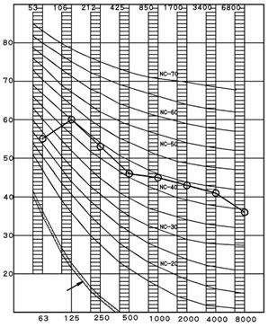
15 9 Sound data Outdoor Unit RX-GV 9 - Sound Pressure Spectrum RX50G Cooling Heating 9 Octave band sound pressure level db (0 db = μ bar) Approximate threshold hearing for continuous noise Octave band sound pressure level db (0 db = μ bar) Approximate threshold hearing for continuous noise Octave band center frequency - IEC (Hz) Octave band center frequency - IEC (Hz) NOTES 50Hz Scale 220~240V Over All (db): (B,G,N is already rectified) A 47 2 Measuring place: measured in an echoic room. 3 Operation noise differs with operation and ambient conditions. 4 Location of microphone. JIS C 962 The operation noise measuring method is in accordance with JIS C 962 NOTES Scale Over All (db): (B,G,N is already rectified) 2 Operation noise differs with operation and ambient conditions. 50Hz 220~240V A 48 3D0577D RX60G Cooling Heating Octave band sound pressure level db (0 db = μ bar) Approximate threshold hearing for continuous noise Octave band sound pressure level db (0 db = μ bar) Approximate threshold hearing for continuous noise Octave band center frequency - IEC (Hz) Octave band center frequency - IEC (Hz) NOTES 50Hz Scale 220~240V Over All (db): (B,G,N is already rectified) A 49 2 Measuring place: measured in an echoic room. 3 Operation noise differs with operation and ambient conditions. 4 Location of microphone. JIS C 962 The operation noise measuring method is in accordance with JIS C 962 NOTES Scale Over All (db): (B,G,N is already rectified) 2 Operation noise differs with operation and ambient conditions. 50Hz 220~240V A 49 3D0576D 4 Split - Sky Air Outdoor Unit
 Approximate threshold hearing for continuous noise Octave band sound pressure level db (0 db = 0.")
 A 52 2 Measuring place: measured in an anechoic room. 3 Operation noise differs with operation and ambient conditions. 4 Location of microphone.")
16 Outdoor Unit RX-GV 9 Sound data 9 - Sound Pressure Spectrum RX7GV Cooling Heating 3 Octave band sound pressure level db (0 db = μ bar) Approximate threshold hearing for continuous noise Octave band sound pressure level db (0 db = μ bar) Approximate threshold hearing for continuous noise 9 Octave band center frequency - IEC (Hz) Octave band center frequency - IEC (Hz) NOTES 50Hz Scale 220~240V Over All (db): (B,G,N is already rectified) A 52 2 Measuring place: measured in an anechoic room. 3 Operation noise differs with operation and ambient conditions. 4 Location of microphone. JISC962 The operation noise measuring method is in accordance with JISC962 NOTES Scale Over All (db): (B,G,N is already rectified) 2 Operation noise differs with operation and ambient conditions. 50Hz 220~240V A 52 3D055789B Split - Sky Air Outdoor Unit 5
17 0 Operation range 0 - Operation Range Outdoor Unit RX-GV 0 6 Split - Sky Air Outdoor Unit


18 Daikin s unique position as a manufacturer of air conditioning equipment, compressors and refrigerants has led to its close involvement in environmental issues. For several years Daikin has had the intention to become a leader in the provision of products that have limited impact on the environment. This challenge demands the eco design and development of a wide range of products and an energy management system, resulting in energy conservation and a reduction of waste. The present leaflet is drawn up by way of information only and does not constitute an offer binding upon Daikin Europe N.V.. Daikin Europe N.V. has compiled the content of this leaflet to the best of its knowledge. No express or implied warranty is given for the completeness, accuracy, reliability or fitness for particular purpose of its content and the products and services presented therein. Specifications are subject to change without prior notice. Daikin Europe N.V. explicitly rejects any liability for any direct or indirect damage, in the broadest sense, arising from or related to the use and/or interpretation of this leaflet. All content is copyrighted by Daikin Europe N.V. EEDEN Please fill out the requested information Please fill out the requested information Daikin Europe N.V. participates in the Eurovent Certification programme for Air conditioners (AC), Liquid Chilling Packages (LCP), Air handling units (AHU) and Fan coil units (FCU), Check ongoing validity of certificate online: or using: Daikin products are distributed by: Naamloze Vennootschap - Zandvoordestraat 300, B-8400 Oostende - Belgium BE RPR Oostende EEDEN /2 Copyright Daikin The present publication supersedes EEDEN-00 Printed on non-chlorinated paper. Prepared by Goekint Graphics NV, Belgium Responsible Editor: Daikin Europe N.V., Zandvoordestraat 300, B-8400 Oostende