Solutions of Electric Power System Stabilization
|
|
|
- Claude Booker
- 5 years ago
- Views:
Transcription
1 Solutions of Electric Power System Stabilization September 15, 2015 Fuji Electric Co., Ltd. 1


 Fuel cell")


 Optimum supply")
2 Overview of Fuji Electric s Power System Stabilization Large power plant Distributed generator & Storage battery Gas supply plant Building (BEMS) Fuel cell Sewage treatment facility Community Energy Management System Fuel cell Fuel cell House Neighborhood facility Distributed generator & Storage battery Gas cooperation Information network Heat network Electric power network Gas network Optimum supply and demand control Gas cogeneration Factory (FEMS) Optimum supply and demand control Industrial park 2
3 Types of power failure and counter measure Instantaneous voltage drop Instantaneous power failure Entire high voltage system need to be compensated for Instantaneous voltage drop? NO Commercial power supply is high quality? NO YES YES NO Energy saving Energy saving NO Energy saving NO Reduction CO2 Reduction CO2 Reduction CO2 YES YES YES Momentary voltage drop compensator (UPS8000H) Cogeneration + High-speed breaker Continuous commercial power supply type UPS with constant voltage control function (UPS8000D) Continuous inverter powered UPS (UPS6000D) + Diesel generator for long power outage 3

4 Fuji Electric Cogeneration System 4
")


5 Overview of Cogeneration System Grid 22 kv Grid Connection Factory Electricity Chiller (Existing) Chilled Water for Air Conditioning GAS Cogeneration Steam Hot Water Benefits of Cogeneration System: Energy Cost Saving Power Source Security when Grid Outage CO 2 Reduction Absorption Chiller Steam Hot Water Boiler (Existing) <Drying> <Steamed /Humidifying> <Calcination> <Concentrated> <Extraction> <Distillation> <Sterilization> <Wash> 5

6 Power Stabilization Example (instantaneous voltage drop) When instantaneous voltage drop (outage) in the commercial power network from thunder occur, PC or control devices are affected such as suspension. Therefore, clients such as semiconductor industry who do not allow instantaneous voltage drop traditionally take measures such as to install UPS to individual loads. Recently, such cases are increasing as to introduce Instantaneous Voltage Drop Avoidance Device to protect total plant, or to introduce Cogeneration + High-speed Breaker for critical loads. Thunder, etc. High Voltage Grid Instantaneous Voltage Drop Avoidance Total plant Uninterruptible Power (2s) Low Voltage Grid Critical Load disconnecting the grid when voltage drop occurs within 20ms. (Only applied to 3.3/6.6kV grid.) 1 Cycle: 20ms at 50Hz 6


7 Reference Site: Fuji Electric Yamanashi Factory Customer benefits: Avoidance of power risk (productivity improvement) Achieving visualization, analysis, and optimization of energy by introducing FEMS Drastically saving the power cost by optimizing the integrated operation and self-sustained operation of the grid power and cogeneration system Drastically saving the fuel cost of the existing boiler system (for air conditioning) by utilizing effectively heat (steam) and electricity Simple single-line diagram of the entire factory Total efficiency of GE : 68.6% Gas cogeneration system Panoramic view of Yamanashi factory Panoramic view of Yamanashi factory 7

8 Reference Site: Fuji Electric Yamanashi Factory The FEMS (Factory Energy Management System) model by the best-mix of electricity and thermal energy : Electricity : Cold energy : Hot energy Conventional model Optimal control FEMS Grid power Chiller Steam chiller Cold water Compressor Production facility Grid power Chiller Fuel cell Hot water Chiller Cold water Compressor Production facility Fuel Boiler Steam Air conditioner Pure water heating Fuel Fuel Gas engine co-generation Boiler Hot water Chiller Steam chiller Steam Air conditioner Pure water heating 8


 1200 1000 800 600 400 400 200 200 0 0 1 3 5 7 9 11131517192123252729313335373941434547 時間 (h) 1200")


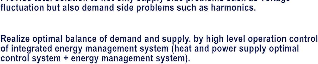
9 Integrated Energy Management System Fuji Integrated Energy Management System utilizes our sensing technology, ITC technology, and data analyzing technology, and realizes minimization of energy consumption by its high level analyzing support and energy-saving control, and optimization of supply/demand balance by advanced operation control of energy supplying facility. Integrated Energy Management System Co-generation optimal control system Energy Management System 電力 (kw) 時間 (h) 電池充電量 (kwh) 放電 G1 G2 G3 G4 G5 充電需要 + 充電充電電力量需要予測 Supply/demand management Supply/demand control Generation control Demand prediction DR Demand prediction Demand adjustment Saving power order Consumption analysis Production planning Record management In-house power generator optimal control system Electricity Controller Sensor Instrumentation sensor/ Control device Power receiving & transmission facility Co-generation system Steam/ heat Factory Building 9
10 Benefits of Cogeneration System Energy Cost Saving The electricity purchased from Grid can be saved - By using the electricity generated from the cogeneration system. - By using the generated exhaust heat (hot water), and creating cold water for air conditioning through the absorption chiller, thus saving the electricity used in the existing chiller. The gas used for the existing boiler can be saved - By using the generated exhaust heat (hot water). Power Source Security when Grid Outage The cogeneration can supply sustainable electricity, thus enhancing the business continuity of the Factory. CO 2 Reduction Factory Promotion: Contribution to the environment 10
11 Approach to Cogeneration Introduction Step1 Check Conditions (1) Estimate Load(Electricity / Chilled Water / Hot Water / Steam) (2) Purpose (Save Energy Cost / Secure & Stable Power Supply) Step2 System Settings (1) Check the Current System (2) Propose the New System (Capacity / Engine / Exhaust Gas Recovery Method) Step3 Simulation (1) Energy Revenue & Expense Calculation (2) Cost Calculation (Initial / Running / Fuel / Maintenance etc.) Step4 Evaluation (1) Energy Saving Amount (2) Environment Adaptation (NOx Regulation / Noise / CO2 Emission etc.) (3) Economics (Simple Payback Period) Step5 Introduction Decision (1) Finalization of the System (2) Cash Flow Calculation and Decision by the Customer 11
12 Questions for Cogeneration Introduction Fuel Natural Gas Other ( ) Future plan for using Natural Gas? Yes / No Contract power(kw) Receiving voltage (kv) /Frequency(Hz) Available Space for Installation (m2) Measures for instantaneous voltage drop Indoor( m2):floor( F ) Outdoor( m2) Air Condition Type Central Type Individual Type Other( ) Boiler Use Status Fuel Yes (Steam / Hot Water ) No Ability : ( t / h) 12

13 Sample: CHP(Cogeneration) System Conditions for grid connection will be discussed with Power Company. 13


14 Cogeneration installation example Gas engine Container type Easy to install Multiple installation example 14

15 Effective use of JCM Reduction of the initial investment by the JCM (Ministry of the Environment) 1/2 of the initial investment cost will be subsidized. Facilitating diffusion of leading low carbon technologies, products, systems, services, and infrastructure as well as implementation of mitigation actions, and contributing to sustainable development of developing countries. Appropriately evaluating contributions from Japan to GHG emission reductions or removals in a quantitative manner and use them to achieve Japan's emission reduction target. Countries: Indonesia, Vietnam, Cambodia, Laos, Bangladesh, Ethiopia, Kenya, Maldives, Costa Rica, Palau 15


16