Modelling to the National Energy Code of Canada for Buildings NECB 2011 with IESVE 2017
|
|
|
- Nathan Barrett
- 5 years ago
- Views:
Transcription
 International Sustainability Consulting Developers of the IES Virtual Environment Chris Flood")
1 Modelling to the National Energy Code of Canada for Buildings NECB 2011 with IESVE 2017 Supporting Guidance By: Integrated Environmental Solutions (IES) International Sustainability Consulting Developers of the IES Virtual Environment Chris Flood V3.0
2 Contents 1 Introduction Performance Compliance Path Getting Started Selecting the Navigator Preliminary Data Setup Proposed Design Building Geometry Location & Climate Envelope Internal Gains & Service Water Heating Loads Operational Schedules Templates of Building & Space Types HVAC System Reference Building Geometry Envelope HVAC System Oversizing Heating System Cooling System Outdoor Air Space Temperature Control Fans Supply Air Systems Heat Recovery Systems Service Water Heating Systems
3 5.13 Part-Load Performance Curves Sizing & Simulation Procedure Results Analysis Unmet Load Hours Reports Support
4 1 Introduction This document is intended as a guide to IESVE users wishing to perform a National Energy Code of Canada for Buildings 2011 (NECB 2011) Division B Part 8 Building Energy Performance Compliance Path analysis. This document is not intended as a comprehensive guide to the standard or the performance path contained therein. This document should be read in conjunction with the NECB standard and is intended for users with experience of the IESVE workflow navigators. The Virtual Environment is fully compliant with ASHRAE 140 and hence qualifies as a tool capable of performing NECB Performance Path calculations, as described in the NECB Standard as follows: If a computer program is used to carry out the compliance calculations, the calculation methods employed in the energy model shall conform to a) ANSI/ASHRAE 140, Evaluation of Building Energy Analysis Computer Programs, or b) An equivalent test method. The following sections provide guidance regarding workflow when using the Virtual Environment (VE) ASHRAE 90.1 Navigator to complete an NECB Performance Compliance Analysis. While there are similarities between the ASHRAE and NECB 2011 performance compliance paths, some differences exist. These differences should be understood sufficiently so that the VE Navigator can be applied with modifications. This document states the requirements of the NECB 2011 performance compliance path and demonstrates how the 90.1 Navigator can be applied to meet the requirements of that code. NECB 2011 applies to new buildings and additions. It is a model code whose aim is to promote consistency across Canada, provide minimum requirements for the design and construction of energyefficient buildings and their envelope, systems and equipment for heating, ventilation and airconditioning, service water heating, lighting, and the provisions of electrical power systems and motors. The code was developed by the Canadian Commission on Building Codes to succeed the previous Model National Energy Code of Canada for Buildings 1997 (MNECB 1997). In Canada, provincial and territorial governments may enact NECB 2011 for compliance and any persons involved in the design or construction of buildings should consult their provincial or territorial regulations to determine applicability. At the time of issuing this document, adoption of NECB 2011 by provinces and territories in Canada was as follows: Adopted: Not Adopted: British Columbia, Alberta, Manitoba, Ontario, Nova Scotia Yukon, Northwest Territories, Nunavut, Saskatchewan, Quebec, New Brunswick, Prince Edward Island, Newfoundland and Labrador 4

5 Further information regarding the current adoption of the NECB standard can be found on the following National Research Council Canada website: The process of creating an NECB 2011 Reference building in the VE, as outlined in the following simple Process Flow Diagram, begins by selecting the ASHRAE PRM Navigator. This guidance document assumes the user has had some training and experience creating energy models in the VE. 5
6 2 Performance Compliance Path NECB 2011 Division B Part 8 allows that the building demonstrate compliance with the code through calculation of the reference and proposed building annual energy use. Annual energy use resulting from the following building elements should be included in the calculation: Space heating equipment Space cooling equipment Fans Interior and Exterior Lighting Devices Service Water Heating Equipment Pumps Auxiliary HVAC Equipment* Receptacle Loads and Miscellaneous Equipment Appliances Elevators and Escalators *Includes Cooling Tower Fans, Humidifiers and other devices not listed in the above categories. Compliance is demonstrated when: a) The annual energy use of the proposed building does not exceed that of the reference building b) The number of unmet heating load hours for each thermal block of both the reference and proposed buildings does not exceed 100 hours. c) The number of unmet cooling load hours for each thermal block of the proposed building do not differ by +/- 10% from the unmet cooling load hours of the reference building. Note: If the requirements of (b) and/or (c) are not met, the capacities of the primary and secondary systems of the proposed or reference building shall be incrementally increased until they are met. 6


7 3 Getting Started To begin the setup process, open the Virtual Environment and select the Navigators Tab. 3.1 Selecting the Navigator Once the Navigators tab has been selected, a drop-down menu will appear. Select ASHRAE 90.1 App. G PRM 2010 and ECB. 7


8 3.2 Preliminary Data Setup Setup of the model preliminary data includes setting the site, location and climate data, selecting the ASHRAE standard, specifying the type of any fossil fuel to be used, creating the building geometry, and setting the building orientation and performing the solar shading calculations. These steps should be completed as normal. IMPORTANT: Modifications will be made later in the workflow and model, so as to realign the reference and proposed buildings with the requirements of the NECB code. This will include, for example, editing of the baseline geometry, envelope and HVAC systems if an NECB reference model modification is necessary. First, the focus will be on the proposed model. The following steps in the preliminary data setup process can be excluded, as they are not a requirement of the NECB Performance Compliance Calculation: Model Orientation and Rotation check Model Orientation and Rotation Report Select ASHRAE Standard The user should select the ASHRAE ECB standard as the basis for the model workflow. Selecting the ECB standard is merely a starting point to assist with the workflow of generating a generic baseline/reference model. Appropriate adjustments will be made to the reference and proposed buildings during the workflow process to realign them with the requirements of the NECB code. This is detailed in Chapter 5. 8
9 4 Proposed Design Building 4.1 Geometry The proposed building geometry should be created to represent the actual building design. This should include actual glazing and door locations and dimensions. Permanent fenestration shading devices and projections shall not be modeled in the reference building. If the proposed building is modeled with exterior shading provided by a nearby structure or building, the reference building shall also be modeled as such. 4.2 Location & Climate Site, Location & Climate The thermal criteria and climate zones referred to in the NECB 2011 code are based on the ASHRAE 90.1 Energy Standard for Buildings Except Low-Rise Residential Buildings with revisions as follows: Moist (A), Dry (B) and Marine (C) definitions have been eliminated, and, Climate Zone 7 has been separated into 7A (5000 to 5999 HDD*) and 7B (6000 to 6999 HDD) *Refers to Heating Degree Days The following data formats are acceptable to represent climatic data: TMY2 (Typical Meteorological Year 2) TMY3 (Typical Meteorological Year 3) WYEC2 (Weather Year for Energy Calculation 2) CWEC (Canadian Weather Year for energy Calculations) CWEC2 IWEC (International Weather for Energy Calculations) CWEEDS (Canadian Weather Energy and Engineering Datasets) The Virtual Environment installation comes complete with CWEC weather files for Canada. If weather data is not available for a specific project location, a representative alternate location can be used as long as the HDD are within 10% of the target location HDD, the climate zones are the same, the same geographic area or characteristics have been used and the January 1% heating design criteria is within 2 o C of the target location s same criteria. When setting the location data and simulation weather file in the ApLocate tool, the user should pay attention to the Design Weather Data tab where outsider air drybulb and wet-bulb temperatures may be adjusted for the purposes of sizing calculations only. The Virtual Environment is equipped with a climate analysis tool located within the VE-Gaia/Climate Navigator toolset. This tool allows the user to perform site-specific climate analysis before any model 9

10 building is performed and calculates HDD and CDD. To access the tool select the appropriate toolset from the Navigator as follows: The climate Navigator automatically produces a report detailing conditions at the specified location, including HDD and CDD values, as follows: 10

\ies\shared Content\Weather.")
11 Where an alternate weather file is to be used which is not CWEC but is of one of the above formats, the user may download such weather files from appropriate sources such as the US D.O.E or Environment Canada, and save to the Weather Data folder of the IESVE installation: C:\Program Files (x86)\ies\shared Content\Weather. The site and location data can be assigned by following the Wizard option of the ApLocate tool: 11

12 Alternate weather files stored in the weather data folder can be assigned at step 4 of the wizard 4-step process: 12


13 4.3 Envelope The proposed building design envelope should be created to reflect the actual design layers and thermal performance values. By selecting the Custom Construction Type step of the Envelope Properties group the construction library wizard is opened where the user may create constructions under each of the envelope categories. Beginning with the external wall category, by selecting Add New Construction followed by Edit New Construction, the design exterior wall construction layers are created. 13


14 The design exterior wall construction is created layer-by-layer and edited to achieve the design overall thermal performance. This process is repeated for each envelope category. Once the design envelope constructions have been created in the constructions library they are then available to be assigned to the proposed building model. To assign each of the envelope categories click and drag a window around the building in model view and select the Assign Constructions tool. 14
 provides default internal loads for lighting, occupants and receptacles for different building types and space functions.")
15 4.4 Internal Gains & Service Water Heating Loads Internal loads representative of building or space type must be modeled identically between the proposed and reference models. NECB2011 Appendix note A (1) provides default internal loads for lighting, occupants and receptacles for different building types and space functions. In the absence of design information, the proposed and reference models should use these values. These values can be found in the prototype model (provided as part of this guidance package: NECB Prototype Model) via the building type or space type templates in the building template manager library. 4.5 Operational Schedules NECB2011 Appendix note A (1) provides operational schedules for occupants, lighting, receptacle equipment, fans, cooling system, heating system and service water heating. These operational schedules can be found in the prototype model library via the profiles database, ApPro. 15
 of the NECB code.")
16 4.6 Templates of Building & Space Types Provided with each building or space type template are the internal gains and schedules of operation detailed in NECB2011 Appendix note A (1) of the NECB code. The user should select the appropriate space type from the Building Template Manager and assign that template to the whole model in the case of the use of a building type template, or to each individual space type in the case of the use of the space type templates. The building and space type templates can be found in the Building Template Manager of the master template library. 16

17 4.7 HVAC System The hvac system of the proposed design building should be modeled as per the actual design. The library of prototype hvac systems available in ApacheHVAC allows the user to model various system types without the requirement for them to be created manually. 17


18 5 Reference Building Following completion of the preliminary data setup and details of the proposed building model, the user can proceed to creating the reference building characteristics. By selecting Generate the Baseline Model a reference model file (named baseline) is automatically created and is then available to the user for viewing and editing. This toggling functionality between proposed and baseline models is also available in the ASHRAE 90.1 Application. 18

19 5.1 Geometry In accordance with the NECB 2011 code, if the total vertical fenestration and door area to gross wall area ratio (FDWR) of the proposed building differs from the maximum permitted by NECB2011 Article , the FDWR of the reference building shall be adjusted proportionally along each orientation until it complies with that article. HDD Reference Building Allowable Fenestration and Door Area Ratio (FDWR) Up to to 7000 (2000 (0.2 x HDD)) / 3000 Above Adjustment of the reference building FDWR is performed post-generation of the reference model file. By returning to ModelIT the user can select the reference building geometry and edit the glazing layout using the glazing editing tools. The VE is also equipped with a geometry reporting feature which can be accessed via the menu bar ModelIT>Model Report, and selecting Glazing % as the report metric. The report output will then appear as follows: 19

 and typing")
20 In addition, the user may view and manually edit the reference building glazing layout and % by accessing the reference building geometry via View>Model>PRM Baseline on the menu bar of the ModelIT Application. If the user is required to edit the reference building glazing area the VE is equipped with a tool to shrink glazing based on user selections. The tool is accessed by first selecting the glazing to be edited (from selecting the entire building or individual rooms or surfaces) and typing shrink into the keyin bar located in ModelIT: The shrink tool will then appear as follows: 20
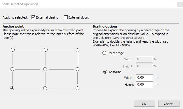
21 21

22 5.2 Envelope The reference building envelope performance characteristics are determined from NECB2011 Part 3 Building Envelope Table Opaque Assemblies and Table Fenestration. Above Ground Opaque building Assembly Zone 4 <3000 Heating Degree Days of Building location in Celsius Degree-Days Zone Zone Zone 7A Zone 7B Zone 8 to 3999 to to 6000 to > Maximum Overall Thermal Transmittance, in W/m 2 K Walls Roof Floors The heating degree days for the building location can be determined from the heating degree-days map, NECB2011 figure A (1), of Section A (1). The VE is equipped with a Target Construction tool which enables the user to automatically create an envelope assembly with a specific U-value and thermal mass factor. The tool is accessed via the Apache Constructions Database and by selecting Tools>Create Target Construction from the menu bar. This tool should only be applied for conceptual analysis. Thermal Mass Following creation of the proposed building constructions the reference building constructions may be created by copying those of the proposed building and adjusting the insulation thickness in accordance with the following statement. 22
23 In accordance with NECB2011 Section A (4)(d) Thermal Mass, the reference building envelope assemblies should follow the layer structure of the proposed building s envelope assemblies (type and order) but the insulation thickness should be varied to match the maximum overall thermal transmittance of NECB2011 Section 3.2. The Thermal Mass should be set to light-weight which corresponds to a framed exterior wall or a 51mm concrete floor slab. The thermal mass of any construction can be viewed in the Constructions Database and modified by adjusting the properties of the layers of that construction. Solar Absorptance The solar absorptance of each opaque building envelope assembly, other than roof, shall be modelled as identical to that of the proposed building envelope. The solar absorptance of the roof assembly shall be set to that of the proposed roof if the actual proposed roof value is not used, or set to 0.7 if the actual proposed roof solar absorptance is used. Solar absorptance can be edited directly in the properties of construction. 23
24 24
25 5.3 HVAC System The reference building hvac system title should not be edited and should remain as the default title of Baseline. This is to ensure the Autosizing procedure is applied correctly at the appropriate stage. The reference building HVAC system selection should be carried out in compliance with NECB2011 Section The following table provides a description of the NECB Reference building HVAC system types: System Number Type of HVAC System Fan Control Type of Cooling system Type of Heating System System 1 Unitary air-conditioner with baseboard heating Constant volume Air-cooled directexpansion with remote condenser System 2 Four-pipe fan-coil Constant volume Water-cooled water chiller System 3 System 4 Single-zone packaged rooftop unit with baseboard heating Single-zone make-up air unit with baseboard heating Constant volume Constant Volume Air-cooled directexpansion Air-cooled directexpansion System 5 Two-pipe fan-coil Constant volume Water-cooled water chiller Hot water with fuelfired water boiler or electric resistance baseboard Fuel-fired or electric resistance water boiler Fuel-fired or electric resistance furnace for rooftop, hot water with fuel-fired boiler, or electric resistance for baseboards Make-up air unit: electric or indirect fuel-fired furnace Baseboards: electric resistance or hydronic with fuel-fired boiler None System 6 Multi-zone built-up system with baseboard heating Variable volume Water-cooled water chiller Baseboards: electric resistance or hydronic with fuel-fired boiler System 7 Four-pipe fan-coil Constant volume Water-cooled water chiller Hydronic with electric resistance or fuel-fired boiler The IESVE ApacheHVAC Prototype Systems Library contains an extensive selection of HVAC systems available for use and autosizable. With some minor modifications, the systems available in the IESVE HVAC library can be used to model any of the systems listed in the table above. The following table 25
26 maps the appropriate system to be selected from the ApacheHVAC library when modelling the NECB 2011 systems: NECB System Type of HVAC system IESVE Prototype System Summary of Required General Modifications System 1 Unitary air-conditioner with baseboard heating 01a Heating airflow off. Insert electric baseboard in room. System 2 Four-pipe fan-coil 09a Add return air branch and controllers. Change boiler to electric resistance if necessary. System 3 System 4 Single-zone packaged rooftop unit with baseboard heating Single-zone make-up air unit with baseboard heating 03a 05e System 5 Two-pipe fan-coil ECB System 005. No heating. System 6 Multi-zone built-up 05e system with baseboard heating Add hot water or electric resistance baseboards to zone. Extend multiplex around entire system. Change central coil to electric or furnace. Switch off zone air heating coil. Add electric or hot water baseboards to zone. Switch off all heating coils. Switch off zone heating coil. Add electric or hot water baseboards to zone. System 7 Four-pipe fan-coil 09a Add return air branch and controllers. Change boiler to electric resistance if necessary. Note: It is the responsibility of the user to ensure the hvac systems modeled as part of the reference or proposed design buildings are appropriate. Demand Control Ventilation IESVE2017 includes new features which allow the user a simple network editing process to add control strategies and controllers to a HVAC network and for those strategies to be included in the Autosizing and annual simulation steps. Demand control ventilation is taken here as an example of one such edit. The user will select a Independent Controller with Sensor from the ApacheHVAC toolbar and place the sensing and controlling points in the correct location on the network. The added controller is shown in the following image: 26


27 The user will then set the correct Link, Sensing and Controlling parameters via the controller dialog. This controller is then ready for Autosizing once the DCV feature of the particular network is activated in the System Parameters dialog: 27
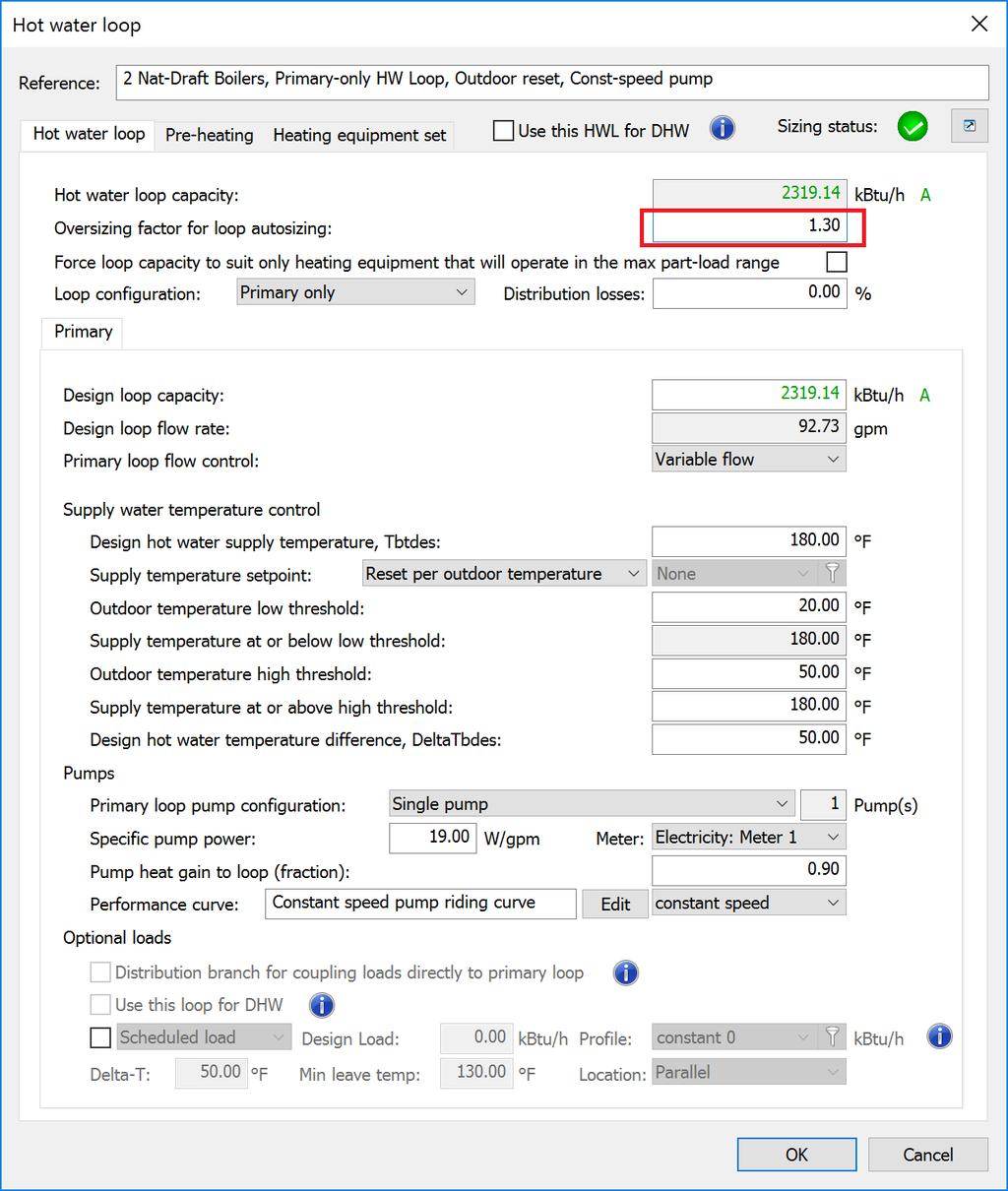
 the percentage of oversizing applied to the proposed building, or, b) 10%.")
28 5.4 Oversizing In accordance with NECB2011 Section , the reference building heating equipment should be oversized by the lesser of a) the percentage of oversizing applied to the proposed building, or, b) 30%. The reference building cooling equipment should be oversized by the lesser of a) the percentage of oversizing applied to the proposed building, or, b) 10%. In order to apply oversizing factors to the reference building, the user should modify the oversizing factor of all zone-level, system-level and central plant capacities as per the factors detailed above. Two examples are shown below in the case of an AHU heating coil and a Hot Water Loop Capacity. 28
29 29

30 5.5 Heating System The setup of the reference building heating system should be carried out in compliance with Section The following aspects of the reference building heating system should be noted also: Number of Boilers In the case of a hydronic heating system, where the heating capacity is less than 176 kw the reference building boiler shall be modelled with one single-stage boiler. Where the heating capacity is between 176 kw and 352 kw the reference building shall be modelled with a) two boilers of equal capacity, or, b) a two-staged boiler which operates in stages with a 1:2 ratio. Where the heating capacity exceeds 352 kw the reference building boiler shall be modelled with a boiler that is fully modulating down to 25% of its capacity. In the VE, boilers can be staged by accessing the Hot Water Loop Dialog>Heating Equipment Set tab: Other required settings such a pump power and hot water loop temperature can also be accessed via the hot water loop dialog in ApacheHVAC. 30

31 Where the reference building contains a furnace, it shall be modelled as having a capacity equal to the building heating capacity up to 66 kw. Where the heating capacity is greater than 66 kw the furnace shall be modelled with a number of stages equal to the capacity divided by 66 kw and rounded up to the nearest integer. The ApacheHVAC library contains default Furnace type heat sources which can be accessed and edited via the Generic Heat Sources tool. 31

32 Part-Load Performance Curves NECB2011 Table A details the part-load performance curve calculations to be applied to each heating source type. Similar to the hot water loop and furnace settings, the part-load performance data can be entered via the heating equipment dialog. 32
33 5.6 Cooling System The setup of the reference building cooling system should be carried out in compliance with NECB2011 Section The following aspects of the reference building cooling system should be noted also: Equipment Performance Characteristics Cooling equipment performance characteristics as a function of part-load shall be modelled in accordance with the part-load performance curves found in NECB2011 Tables C to F. Number of Chillers In the case of a hydronic system, where the cooling capacity is less than 2100 kw, the cooling plant shall be modelled with one water chiller. Where the cooling capacity is greater than 2100 kw, the cooling plant shall be modelled as two equally sized water chillers each with half the capacity of the total cooling capacity. Other required settings such as pump power and chilled water loop temperature can also be accessed via the hot water loop dialog in ApacheHVAC. Where the reference building cooling equipment is a direct-expansion type, it shall be modelled as having a capacity equal to the building cooling capacity up to 66 kw. Where the cooling capacity is greater than 66 kw the system shall be modelled with a number of stages equal to the capacity divided by 66 kw and rounded up to the nearest integer. For water-cooled systems, heat rejection to atmosphere shall be modelled in compliance with NECB2011 Article

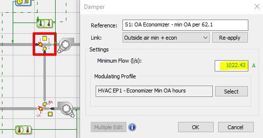
34 5.7 Outdoor Air Outdoor air ventilation rates shall be modelled identically to the proposed building design. Demand controlled ventilation shall be included in the reference building model except in the case of heated parking garages. Outdoor air ventilation rates can be set via the System Parameters>Room Ventilation & Exhaust The user may choose to select the ASHRAE 62.1, user-specified rates or the ASHRAE 170 methodology. Irrespective of the basis of the outdoor air calculation methodology, rates will be applied identically between reference and proposed models. Finally, the user can check the minimum outdoor air volume for each system by double-clicking on the OA Economizer and viewing the minimum flow setting: 34
35 35

36 5.8 Space Temperature Control NECB2011 Article refers to required temperature setpoint adjustments of the reference building in the case where the proposed design is served by in-floor, in-ceiling or in-wall radiant heating and/or cooling systems. In this case, the reference building heating and cooling setpoints should be set 2 o C warmer and 2 o C cooler respectively than the proposed design building. Temperature setpoints for the reference building can be accessed via the System Parameters tool of the Reference building HVAC system following its setup. Individual HVAC schedules of operation and temperature setpoints can be created for each System, Zone and/or space using the Schedules and Setpoints tool of the above System Parameters tool. For example, a separate scheduling and temperature control strategy with a 4-character prefix titled NECB or Sys1 etc, can be created and assigned as appropriate. 36
37 37

38 5.9 Fans NECB2011 Article details the requirements for modelling of fans in the reference and proposed building models. Fan performance curves can be entered for the reference and proposed building models via the fan dialog in ApacheHVAC. Section of NECB2011 discusses the minimum performance requirements of constant-volume and variable-volume fans. While the proposed design should be modeled to reflect the actual design fan performance curves, the baseline building should reflect the performance characteristics stated in NECB2011 Section The reference system fan characteristics follow the Autosizing process. In order for the user to be able to edit the reference system fan power and fan curve data the user should delete, and replace, each system and zone level fan. Once the fan power calculations have been performed by the user, the individual fan power values can be entered into the baseline systems fan curve data. The fan curves can be created or edited by opening the fan dialog (double-click on the system fan icon) and entering the relevant data as shown in the example below: 38

39 5.10 Supply Air Systems In accordance with Article supply air systems for heating and cooling should be sized with temperature differences of 21 o C and 11 o C respectively. Supply air temperature setpoints and derived delta-t can be set via System Parameters>Zone Loads & Supply Airflows in ApacheHVAC. 39
.")
40 5.11 Heat Recovery Systems Where a ventilation heat recovery system is to be used in the reference and/or proposed design buildings in accordance with Article , the user can access those settings via System Parameters>System Parameters (tab). 40


41 5.12 Service Water Heating Systems Service water heating flow rate is initially set at the building template level under Template>Space Conditions>DHW. With the HVAC Methodology set to ApHVAC, all DHW loads will be served by the userspecified ApacheHVAC System. Service hot water loads can be served by the building heating hot water loop or by other heating sources not part of the building heating system either by selecting the appropriate setting in the heating hot water dialog, or, by creating a separate heating source in accordance with Article
 Service Hot Water Heating Plant Article 8.4.")
42 5.13 Part-Load Performance Curves Part-Load performance curves should be calculated for the following reference building systems: Boiler (standard, condensing & modular) Furnace DX Cooling Electric Chiller Cooling Tower Air-Source Heat-Pump Heating Capacity Absorption Chiller Cooling Capacity (standard, steam-driven, direct-fired) Service Hot Water Heating Plant Article provides detailed calculation methodologies for determining the part-load curves of each of the above items of plant. The part-load characteristics can then be entered via the equipment dialog for each item of plant. An example is shown below in the case of a part-load chiller. 33

43 6 Sizing & Simulation Procedure Following completion of the setup procedure for both the reference building and proposed design building envelope, thermal templates, ventilation, DHW and hvac conditions the user may proceed to performing the hvac load sizing and annual simulation calculations. Both reference and proposed building loads calculations may be performed via the appropriate sizing step of the workflow navigator, and, both the reference and proposed building sizing calculations can now be performed in parallel to reduce overall calculation times. 34

44 7 Results Analysis In order to demonstrate compliance with the NECB2011 performance compliance path, the annual whole-building energy-use of the proposed design as modeled must be equal to, or better than, that of the baseline building. Both models are simulated following completion of the sizing procedure, Autosizing of the baseline systems (and proposed systems at concept stage) and modeling of the actual proposed design (when design information becomes available). After simulations are complete the user can access a detailed breakdown of energy-use for each building from the Results stage of the workflow navigator: A results report is created and saved to the Content Manager (in Tools menu) and results are presented in the following format for each building: 35
 has some combination of gas & electricity fuel sources. 7.")
45 At this point the user may copy and paste the report into a spreadsheet for a comparative analysis, or, may extract results per end-use and energy-meter designation via the Vista Pro results analysis module: This can be particularly useful if an energy end-use (e.g. heating, cooking, DHW) has some combination of gas & electricity fuel sources. 7.1 Unmet Load Hours Reports Unmet Load Hours should be determined for the Proposed and Reference buildings following annual simulation of each model. The following guide discusses how to extract Unmet load hours and common causes of high Unmet hours results. IESVE Unmet Load Hours Troubleshooting Guide 36
46 8 Support For more information, please refer to the following resources: Contacts in Canada: Chris Flood (West Coast) Jean Carriere (East Coast) IES Technical Support: IES Learning Videos: IES YouTube Channel: IESVE User Forum:


47 38