300-Watt Power Source Development at the Jet Propulsion Laboratory
|
|
|
- Felix Green
- 5 years ago
- Views:
Transcription
1 300-Watt Power Source Development at the Jet Propulsion Laboratory Presented by: Thomas I. Valdez Industry Day Ft. Hood, Texas April 12 to 14 th, 2005
2 Presentation Outline DMFC Overview Program Discussion Overview of Power Source Design System Performance Analysis of System Performance Program Conclusions
3 Fuel Cell Team Jet Propulsion Laboratory Program Managers R. Surampudi (Power Systems Manager) R. Liang (Army Program Manager) Technical Team T. I. Valdez (Principal Investigator) S.R. Narayanan (DMFC Team Leader, Supervisor) A. Kindler (Subsystem Design) E. Baez (Packaging) G. Klose (Mechanical Design) A. Abatahi (Electronics) M. Young (System Integration) F. Clara (Lab Materials Processing) P. Shakottai (Thermal and Fluids Modeling) Samad Firdosy (Laboratory Support) L. Slootsky (Laboratory Support) I. Marr (Subsystem Testing) Industry Partners Giner Electrochemical System, LLC C. Cropley Fuel cell stack hardware Donaldson Company Inc. R. Canepa Air filtration development Jerez Industries R. Jerez System component fabrication
4 DMFC Overview
5 The Direct Methanol Fuel Cell CO2 Water Direct Methanol Fuel Cell Reaction: Anode: CH 3 OH + H 2 O 6H + + 6e - + CO 2 Cathode: 3/2O 2 + 6H + + 6e - 3H 2 O Cell: CH 3 OH + 3/2O 2 CO 2 + 2H 2 O H + H + DMFC Advantages Safety of handling a liquid fuel versus compressed gas fuel tank (i.e. Hydrogen) Low methanol concentration (<3%) in the working fuel loop Methanol H + H + H + H + e - e - V Air
6 The Benefits of A DMFC Power Source 4 Battery Configuration 2 Battery Configuration Battery DMFC Battery DMFC Mass (lb) Volume (ft 3 ) Energy (Whr) Substantial reduction in mass Increased energy capacity Increased operating time Comparison based on information from TESCO using a 4-battery and 2- battery test configuration without recharging
7 JPL Direct Methanol Fuel Cell Program Description
8 Objective, Background and Requirements Objective Develop direct methanol fuel cell technology and demonstrate a 300-Watt prototype power source. Background The Army currently uses four deep cycle marine batteries to provide auxiliary power to armored vehicle external test instrumentation. The batteries mass is 138 kg (305 lb) and are limited to 8 hours of operation without recharging. Summary of Requirements Power 300 W (Continuous) Run Time: 100 hr (Continuous) Energy: 30,000 Whr Target Mass: 36 kg (80 lb) (Including Fuel) Other Attributes: - Rapid Startup - Field Refueling for Extended Operation - No Recharge Time -Quiet - Low Thermal Signature

9 Summary of Accomplishments Goal: Develop a 300 Watt DMFC Power Source for powering test instrumentation on Armored Vehicles Integrated DMFC Unit Developed A 300-Watt DMFC based power source design that can deliver 100hr of continuous operation has been designed and integrated The CBE figures of merit for this power source are 540 Whr/kg and 243 Whr/L for the specific power density and volumetric power density respectfully Scaled up cells from 25-cm 2 active area to 80 cm 2 A five-cell stack has been scaled up to 80 cells and was demonstrated to deliver 370 Watts during bench testing Short stack testing reveal ruthenium dissolution into the polymer electrolyte membrane but did not have an impact on cell electrochemical performance Demonstrated autonomous operation capability of a complete fuel cell system in a box Operated continuously at a net output of 50 Watts for 8 hours Operated test instrumentation hardware (60 to 70 Watts) for 0.5 hours
10 Future Development A 300-Watt DMFC system design has been completed The functionality of this system was demonstrated System design challenges and issues have been identified Industry members should develop this system into a pre-production prototype JPL s future role will be to assist the US Army with technical support to facilitate the delivery of a pre-production prototype power source
11 Overall DMFC System Design
12 Requirements Power Source: Power 300 W (Continuous) Run Time: 100 hr (Continuous) Energy: 30,000 Whr Target Mass: 36 kg (80 lb) (Including Fuel) System Startup: Instantaneous when ambient temperature is greater than 5 o C (41 o F) Field refueling Operational Environment: Military war simulations Air Quality: High dust concentration, 20 times zero visibility (~ 5 gm/m2 of ACS Coarse 30 microns dust) Air Temperature: -17 to 45 o C (113 o F) Relative Humidity: 0% Attitude Sensitivity: +/- 45 o to vertical Unit must be protected during wash rack cycle. Shock and Vibration: Survive a three-foot drop on concrete MIL-STD-810 Requirements for the pre-production prototype to be finalized by the Army


13 Technical Challenges Key Technical Challenges Meeting environmental requirements Continuous operation in thermal and water balance System size and volume with contained fuel Ruggedized operation Safety of methanol handling Challenges to be addressed Cost Effective Membrane Electrode Assembly (MEA) and System Fabrication Power Source Longevity Attitude Insensitive Operation Ruggedized operation
14 Challenges Resulting from Environmental Temperature Power Source Environmental Operating Temperature and Humidity: 45 o C, 0% RH At 0% RH, MEA operating stoichiometry will define system volume An airflow stoichiometry in the range of 1.7 to 1.8 is required for a DMFC stack, operating at 60 o C, without an exhaust condenser, to operate in water balance in 0% RH The smaller the temperature difference between the system operating temperature and the environmental temperature, the larger the radiator surface area required for cooling A DMFC-based power source operating at 60 o C in an ambient environment of 45 o C allows for only a 15 o C differential in temperature and results in an increased radiator size. Water Balance DMFC System Operating at 60 o C Calculation Assumptions Applied Current:140 ma/cm 2 X-Over: 22.7 ma/cm 2
15 Stack Design Challenges Operating Temperature Heat rejection: Environmental temperature 45 o C Water balance: MEA operation at low airflow is required to maintain a water balance without the use of a condenser Orientation Sensitivity Efficient product water removal is required during operation Stack pressure drop, specifically the cathode pressure drop should be minimized to reduce ancillary power demand Stack Sizing Sized to required power output, system ancillaries and power conditioning Stack operating voltage should be selected to match with a higher efficiency power converter
16 Electronics Subsystem Challenges Methanol Concentration Control Operation time: 100 hours in-field refueling required Active concentration control via a methanol sensor is suggested System Startup Instant startup 15 minute startup from 5 o C acceptable Power Management Power source is required to be load following Stack voltage should be controlled from spiking to protect electronics Ancillary power demand Must reduce power required by ancillary to increase system operating efficiency Electronics Survivability Electronics should be designed to operate at the maximum power source enclosure operating temperature A minimum temperature of 60 o C is suggested Electronics ruggedization
 M1A1 Abrams Rear Bustle Rack Bradley Fighting Vehicle Bustle Rack Abrams Commanders Accessory Box (M1A1,")

17 Operational Challenges M1A2 Abrams ( M1A1 Abrams Rear Bustle Rack Bradley Fighting Vehicle Bustle Rack Abrams Commanders Accessory Box (M1A1, M1A2, and M1SEP) System is required to operate in-the-field System should be insensitive to: Vehicle Exhaust Battlefield Contaminants System is configured to fit the Abrams rear bustle rack System can be configured to fit the Abrams commanders accessory box System redesign required to fit the Bradley fighting vehicle
18 Overview of the DMFC System Design
19 Subsystems + - Electronics Circulation Pump Air Filter Stack Subsystem - + Heater Fuel In Stack Air In Methanol Sensor Fuel Out Bypass Valve Air Out Methanol Injection Pump Pure Methanol Radiator Air/ Water Air Exhaust Vapor Cooler Gas-Liquid Separator CO 2 Thermal Subsystem Sump Pump Air Exhaust Fan Water Injection Pump Fuel Subsystem Sump Tank Sump Trough

 Fuel Tank Fuel: Methanol(Supplied from internal fuel tank) Capacity: 30000 Whr Tank Volume: 32 L (1.")
 Operational Environment: Air Quality: High dust concentration, 20 times zero visibility (~ 5 gm/m 2 of ACS")
 Air Temperature: -17 to 45 o C (113 o F) Attitude Sensitivity: +/- 45 o to vertical")
20 300W Direct Methanol Fuel Cell Power Source Specifications System Specifications Electrical: Output Voltage: 24 V Power: 300 W Max Current: 12.5 A Physical: Power Source Dimensions: 31.5 in x 20.7 in x 11.5 in Mass: 55.6 kg (122.6 lb) Volume: 123 L (4.3 ft 3 ) Figures of Merit: Whr/kg, 243 Whr/L Fuel Cell System System Mass: 17.7 kg (39 lb) Fuel Tank Fuel: Methanol(Supplied from internal fuel tank) Capacity: Whr Tank Volume: 32 L (1.1 ft 3 ) Fuel Mass: 25.2 kg (55.5 lb) Operational Environment: Air Quality: High dust concentration, 20 times zero visibility (~ 5 gm/m 2 of ACS Coarse 30 microns dust) System Startup: Instantaneous when ambient temperature is greater than 5 o C (41 o F) Wet Storage: 5 to 70 o C (158 o F) Air Temperature: -17 to 45 o C (113 o F) Attitude Sensitivity: +/- 45 o to vertical Shock and Vibration: Survive a three-foot drop on concrete. Unit must be protected during wash rack cycle.


21 System Integration Gas Expander 80 Cell DMFC Stack Circ. Pump Heat Exchanger Exhaust Blower Fuel Tank Methanol Sensor Startup Heater Startup Battery

22 Component Percent of Power Source Mass The fuel mass and structures represent 80% of the power source mass A DMFC power source can achieve the highest energy density when the fuel mass represents a large fraction of the total system mass

23 Component Percent of Power Source Volume System operating temperature and operating environment have a clear impact on radiator volume
24 System Demonstration

25 Power Source Performance, System operating conditions: 1.45M, 45 o C Powering ACMS System Hardware
26 Results and Observations from the System Demonstration During the demonstration, the power source operated autonomously with the operating logic being driven by an external computer. The system started up in 18 minutes during the system demo The stack output power was over 150 Watts and the system delivered an output power of 50 Watts for over 8 hours. The power output was lower than expected After 8 hours of operation, ACMS systems electronics, which consumed approximately 70 Watts, were operated for half an hour. During the 8.5 hour continuous test, the system consumed approximately 1.3 L of pure methanol resulting in a fuel to electrical energy conversion efficiency of 7%. This value of system efficiency is to be expected considering that the system was not operating at its optimum power output and that 60% of the output from the stack was consumed in running the ancillaries. Water accumulation was noticed in the stack exhaust manifold. The water accumulation was a result of the air diffuser on the stack exhaust side saturating with water and a stack leak rate that was greater than the designed volumetric pumping speed of the sump pumps. The test was concluded because of water accumulation in the stack exhaust manifold.
27 System Demonstration Summary After the system demonstration, the program focused on performance recovery Fault-tree analysis was performed on the system The fault-tree analysis revealed that cathode flooding was the primary reason for system performance decline The experiments performed for the fault-tree analysis were: Stack test-stand testing Stack tear down Advanced single cell MEA testing The conclusions from the analysis of system performance defined by the fault tree are: Fluid accumulation in the stack to be addressed by design changes Stack leakages attributed to poor sealing System performance decline was caused by cathode flooding Ruthenium migration from the anode to the cathode of the MEAs manifested itself as cathode flooding Commercial platinum-ruthenium catalyst appear to be stable during fuel cell operation
28 Analysis of System Performance Stack Testing
29 Testing and Analysis of Failure Modes System Performance Goals System Output, 300W Autonomous Operation, 100hr High Ancillary Drain Low Stack Output Water Balance Sealing Un-optimized Operating Point Stack Design Issues MEAs Membrane Catalyst Electrode Structure Anode Compartment Cathode Compartment Stack Torque Catalyst Stability Legend: Fuel Flow Rate Methanol Concentration CO 2 Removal Air Distribution Cathode Flooding Not Investigated Failure Path Diffuser Materials Air Flow Fields Resolved Investigated

30 Performance Recovery, Stack Performance, Goodman Filter Material # , Applied Load, 50 ma/cm 2, Airflow 41.9 LPM
31 Performance Recovery, Stack Performance, Goodman Filter Material # , Applied Load, 50 ma/cm 2, Airflow 41.9 LPM
32 Performance Recovery, Air Subsystem Configuration Studies 0.5M Methanol, 50 o C, 41 LPM Air Teflonized Carbon Cloth Goodman Filtration Filter Material # Stack Voltage: 30.4V Stack Power: 121.6W Blower Configuration Stack Voltage: 27.8V Stack Power: 111W Stack Voltage: 34.7V Stack Power: 138.8W
33 Performance Recovery, Air Subsystem Configuration Studies Air Leak Rate: PSIG


34 Stack Sealing Not Sealed Sealed
35 Sealed Stack Performance 50C, 0.5M, 100LPM Airflow

36 Sealed Stack Performance 50C, 0.5M MeOH, Hot Air Blower (Warm, Dry Air)
37 Analysis of System Performance Stack Teardown
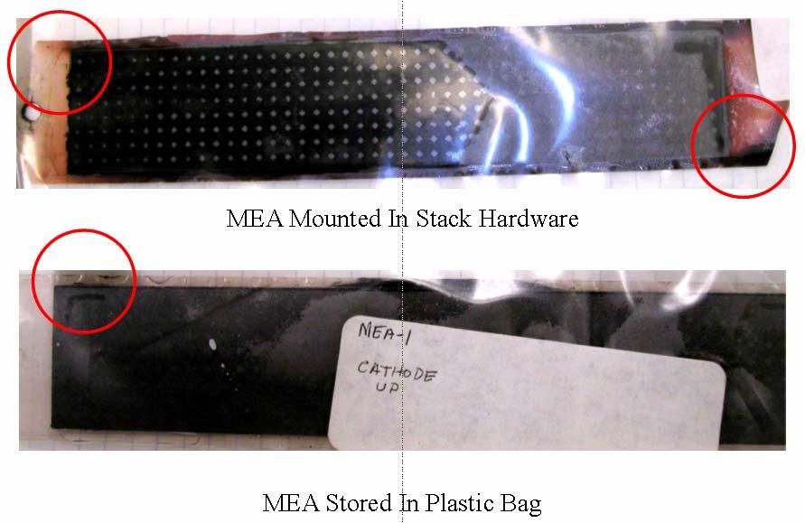
38 Discolored MEAs
39 Discolored MEA Testing No Impact on MEA performance is apparent for discolored MEAs


40 Cathodes of MEAs from the stack exhibited increased wettability compared to a fresh MEA. Patches of dark gray deposits found on various parts of the cathode The areas with dark deposits were more wettable than the lighter areas. Several representative MEAs showed the same type of cathode changes Areas under the flow field pins remained non-wettable Flow field impressions were light and did not appear to damage the cathode papers Observations on MEAs from the 80-cell stack Non-Wetting Dark Deposits Area Under Flow Pin Wetting
41 EDAX Analysis


42 Diffuser Cloth Brownish black ruthenium oxide precipitated at the cathode is washed down by water and absorbed on diffuser.
43 Impact of Stack Performance Decline on Stack Output Power
44 Analysis of System Performance Advanced MEA Studies
45 Advanced MEA Studies Objective: To determine the stability of platinum-ruthenium catalyst and effect of carbon paper Teflon content for DMFC operation MEA Compositions MEA# , Anode: JPL, Cathode: 15% Teflon MEA# , Anode: Johnson Matthey, Cathode 15% Teflon MEA# , Anode: Reduced Johnson Matthey, Cathode 15% Teflon MEA# , Anode: Johnson Matthey, Cathode 5% Teflon (Standard) All MEAs were fabricated with the same painting technique, catalyst loadings and hot-press conditions

46 Ru Migration Studies, 250-hr Durability Test 50C, 0.5M MeOH, 60mA/cm2, High Flow Rate, Air 250 hours of testing complete
47 Post 250-hr Durability Testing Performance Summary MEAs fabricated with the commercial Johnson Matthey catalyst showed the least performance decline The MEA fabricated with the reduced Johnson Matthey anode catalyst, MEA# , performed similar to the MEA fabricated with the JPL catalyst, MEA The test standard, MEA# , performed the best during the durability experiments The rate of voltage decay for all MEAs tested is similar to values observed in the past
48 MEA Analysis - MEA , JPL-Anode, 15-Cathode 60C, 0.5M MeOH, ~1 LPM, 0 PSIG, Air Lower operating currents post 250-hours of testing
49 MEA Analysis IRC Anode Polarization 60C, 0.5M MeOH Anodes stable after 250 hours of testing
50 MEA Analysis Half Cell Analysis MEA , JPL-Anode, 15-Cathode 60C, 0.5M MeOH, ~1 LPM, 0 PSIG, Air Cathode degradation after 250 hours of testing


51 Typical View of an MEA After the 250-hr durability Test Pin cushion pattern Cathode Anode


52 Cathode Hydrophobic Characterization Water Droplet Experiments Slight change in hydrophobicity after 250 hours of testing 15% Teflon Wetting 15% Teflon, MEA# , JM 5% Teflon, MEA# , JM
53 Durability Test Summary Four MEAs have completed durability testing in excess of 250 hours The cells were disassembled and individually tested in the single cell test stand Testing in the single cell test stand has revealed irreversible voltage decay on the cells The voltage decay rate was found to be in the range of to V/hr at 100mA/cm 2 which is in the range previously determined for MEAs fabricated in a similar fashion The voltage decay resulted in a an average decline of cell power of 20% at a 100 ma/cm 2 EDAX analysis performed on the MEAs has shown that the commercial platinum-ruthenium catalyst is stable during DMFC operation
54 Program Conclusions
55 Power Source Testing Conclusions A 300W DMFC based power source design that can deliver 100 hours of continuous operation has been designed and fabricated The CBE figures of merit for this power source are 540 Whr/ kg and 243 Whr/ L for the specific power density and volumetric power density respectfully A five-cell stack has been scaled up to 80 cells and was demonstrated to deliver 370W Demonstrated autonomous operation capability of a complete fuel cell system in a box Operated continuously at a net output of 50 Watts for 8 hours Operated test instrumentation hardware for 0.5 hours Stack performance decline due to cathode flooding and ruthenium dissolution and thus limited power source output
56 Recommendations MEAs: DMFC Membrane Electrode Assemblies (MEAs) should be developed that can operate for duration greater than 5000 hours with less than a 10% decline in power output Stack Subsystem: A stack should be designed that can address reactant avaliability to the MEAs electrodes during in-operation and limit shunt currents The externally manifolded stack design limited orientation sensitivity, complicated water collection and exposed the MEA to an over abundance of oxygen The MEAs access to oxygen, particularly at the cathode, contributed to ruthenium dissolution from the anode The current collection/water collection scheme allowed the system to sustain shunt currents which also contributed to ruthenium dissolution from the anode Water accumulated at the manifolds during the system demonstration that blocked uniform airflow to portions of the stack and may have contributed to shunt currents Fuel Subsystem: The gas liquid separator (GLS) should be designed to allow for better gas bubble (from heating and liquid flow) rejection The GLS design limited the fuel liquid flow rate by restricting liquid flow via gas accumulation During startup, bubbles could accumulate in the heating module and stop fuel circulation Electronics Subsystem: Purchase or fabricated a power converter with an input voltage range that spans the stack operating voltage range The system power converter had a limited input voltage range of 18 to 36 volts The stack voltage could rise to as high as 64 volts during load changes


57 Acknowledgements The work presented here was carried out at the Jet Propulsion Laboratory, California Institute of Technology for the National Aeronautics and Space Administration. This research was sponsored by Ms. Lisa Davis from the Office of Operational Test and Evaluation, Dr. Deryn Chu of the Army Research Laboratory, was managed by Dr. George Shoemaker, Executive Agent for Embedded Instrumentation projects, and Mr. Henry C. Merhoff of the US Army Operational Test Command, Ft. Hood. Dr. Stephen Zakanycz of Institute for Defense Analyses provided both technical and programmatic consulting assistance to this program.