Chapter 5: Gas Processing
|
|
|
- Lynette Norton
- 5 years ago
- Views:
Transcription
1 PTRT 2470: Petroleum Data Management III Facilities Chapter 5: Gas Processing Gas Dehydrator Gas Compressor Sweetening LNG
2 Gas Dehydration and Processing Dehydration by Adsorption Dehydration by Absorption Removal of acid gases
3 Natural Gas Natural gas is a complex mixture of hydrocarbons, with a minor amount of inorganic compounds. It is an essential resource. It is invisible and odorless. Natural gas, as it exists underground, is not exactly the same as the natural gas that comes through the pipelines to our homes and businesses. Natural gas, as we use it, is almost entirely methane. However, when we find natural gas underground, it comes associated with a variety of other trace compounds and gases, as well as oil and water, which must be removed. Natural gas transported through pipelines must meet purity specifications to be allowed in, so most natural gas processing occurs near the well. The base of natural gas is methane (CH 4 ), the simplest hydrocarbon (organic compound consisting of carbon and hydrogen atoms). Normally, it also includes heavier hydrocarbons such as ethane (C 2 H 6 ), propane (C 3 H 8 ), butane (C 4 H 10 ), and some nonhydrocarbon admixtures. Natural gas can exist in the form of gas fields in formations of some rocks, as gas caps (above crude oil), and in dissolved or crystalline forms. Typical unpleasant smell is added to natural gas deliberately and is called odorization. Sulfur compounds are usually used as odorants, i.e. substances with unpleasant smells. Gas leaks can be easily identified exactly due to the odorization. The heating value of natural gas usually varies from 700 Btu/scf to 1,600 Btu/scf
4 Natural Gas Classification Classification by Formation Location The natural gases can be classified as conventional natural gas, gas in tight sands, gas in tight shales, coal-bed methane, gas in geopressured reservoirs, and gas in gas hydrates. Conventional natural gas is associated or nonassociated gas or condensates Gases in tight sands are found in many areas that contain formations generally having permeability of to 1 millidarcy (md). The largest portion of the gas resource is found in the Green River Basin of Wyoming, the Piceance Basin of Colorado, and the Unita Basin of Utah Gases in tight shales are found in the eastern United States (Kentucky, Ohio, Virginia, and West Virginia). Of these, eastern Kentucky and western West Virginia are considered the most important. Coal-bed methane is the methane gas in minable coal beds with depths less than 3,000 ft. Although the estimated size of the resource base seems significant, the recovery of this type of gas may be limited owing to practical constraints
5 Geopressured reservoirs are found in many parts of the world trapped fluid under clays the pressure and temperature of which exceed those normally anticipated at reservoir. located predominantly both onshore and offshore in a band along the Gulf of Mexico; In length, the band extends from Florida to Texas; in width, it extends from about 100 miles inland to the edge of the continental shelf Gas hydrates, discovered in 1810, are snow-like solids in which each water molecule forms hydrogen bonds with the four nearest water molecules to build a crystalline lattice structure that traps gas molecules in its cavities. Gas hydrate is a highly concentrated form of natural gas Classification by Content The natural gas is characterized in several ways dependent on the content of these components: Wet gas is raw gas with a methane content of less than 85% Dry gas is raw or treated natural gas that contains less than 15 liters of condensate per 1000 sm 3. (0.1 gallon per 1000 scf). Sour gas is raw gas with a content of more than 5.7 mg hydrogen sulfide (H 2 S) per scm (0.25 grains per 100 scf), this is about 4 ppm.
6 Acid gas has a high content of acidic gases such as carbon dioxide (CO 2 ) or H 2 S. Pipeline natural gas specification is typically less than 2% CO 2. Acid gas fields with up to 90% CO 2 exist, but the normal range for sour raw gas is 20-40%. Condensates are a mixture of hydrocarbons and other components. These are normally gaseous from the well but condense out as liquid during the production process. This is a refinery and petrochemical feedstock. Raw gas is processed into various products or fractions: Natural Gas in its marketable form has been processed for a specific composition of hydrocarbons, sour and acid components etc. and energy content. Content is typically 90% methane, with 10% other light alkanes. Natural Gas Liquids (NGL) is a processed purified product consisting of ethane, propane, butane or some higher alkanes separately, or in a blend. It is primarily a raw material for petrochemical industry. Natural gas, as sold to the consumer, is mainly methane. Gas wells (and the gas on top of oil wells) contain 5% to 20% of gases and 'gasified liquids' that are not methane. These 'other' hydrocarbons in the natural gas (methane) stream (called NGL) are either- (1) gaseous hydrocarbons that can be relatively easily turned into a liquid with application of moderate pressure or freezing, or (2) liquid at normal temperatures and pressures (known as natural gas condensate, or 'natural gasoline')
7 Liquefied Petroleum Gas (LPG) refers to propane or butane or a mixture of these that has been compressed to liquid at room temperature (200 to 900 kpa depending on composition). LPG is filled in bottles for consumer domestic use as fuel, and is also used as aerosol propellant (in spray cans) and refrigerant (e.g. in air conditioners). Energy to volume ratio is 74% of gasoline. Liquefied Natural Gas (LNG) is natural gas that is refrigerated and liquefied at below -162 C, for storage and transport. It is stored at close to atmospheric pressure, typically less than 125 kpa. As a liquid, LNG takes up 1/600 of the volume of the gas at room temperature. Energy to volume ratio is 66% of gasoline. After transport and storage it is reheated/vaporized and compressed for pipeline transport. Compressed Natural Gas (CNG) is natural gas that is compressed at 2-2,2 MPa to less than 1% of volume at atmospheric pressure. Unlike higher alkanes, methane cannot be kept liquid by high pressure at normal ambient temperatures because of a low critical temperature. CNG is used as a less costly alternative to LNG for lower capacity and medium distance transport. Methane for vehicle fuel is also stored as CNG. Energy to volume ratio is typically 25% of gasoline.
8 Sales gas specifications The exact sales gas specification is specified by pipeline operators and distributors. Typical standard sales gas requirements are for the following parameters: Volume is measured in standard cubic meters (scm) defined as 1 m 3 at 0ºC and kpa or standard cubic feet (scf) as 1 ft3 at 60 F and psia Calorific value specifies the total amount of energy per unit generated during combustion of the gas. The value is used to calculate the amount of energy delivered. Several values are listed: Gross calorific value or gross heat of combustion: is the heat released when a specific quantity of fuel in mixture with air is ignited and the end products have returned to the initial temperature, normally 25ºC. EU specifications are typically 38.8 MJ (10.8 kwh) ±5% per scm. In the US 1030 BTU ±5% per scf. Net calorific value or net heat of combustion: is the net heat generated when the water vapor in the gas does not condense (water forms during combustion) and can be 10% lower.
9 Wobbe index measures the heating effect that a burner is exposed to during combustion. A higher value means a greater thermal load on the burner. Different gases with the same Wobbe index will impose the same load on the burner. An excessively high value is a safety hazard as it can lead to burner overheating and to excess production of carbon monoxide during combustion. Calorific value and Wobbe index can be adjusted by blending gas from different sources as well as by addition or removal of nitrogen (N 2 ) Methane Number is a value similar to octane value for gasoline, and is important when the gas is used for internal combustion engines (as CNG). Hydrogen Sulfide and Overall Sulfur Content both hydrogen sulfide (H 2 S) and total sulfur must be reduced. H 2 S is toxic as well as corrosive for the pipeline as it forms sulfuric acid (H 2 SO 4 ) and should be kept as low as possible. Typical maximum values are 5 mg per scm. of H 2 S and total sulfur at 10 mg per scm. Mercury should be kept below ppb (parts-per-billion) which is its detectable limit. The goal is to limit emissions and to prevent damage to equipment and pipelines by mercury amalgamation which would make aluminum and other metals brittle.
10 Dew point is a temperature below which some of the hydrocarbons in the gas might condense at pipeline pressure, forming liquid slugs which could damage the pipeline. The gas must also be clear of all water vapor to prevent the formation of methane hydrates within the gas processing plant or within the sales gas transmission pipeline. Particles and other substances: must be free of particulate solids and all liquids to prevent erosion, corrosion or other damage to the pipeline and satisfy limits on carbon dioxide, nitrogen, mercaptans etc. Additives: when the natural gas is intended for domestic use, Tetrahydrothiophene (THT) is added so that the otherwise odorless natural gas can be detected in the event of a gas leak. The sulfurous smelling substance added is equal to a sulfur content of 4-7 mg per scm.
11 Calorific Value of Natural Gas 1 standard cubic feet (scf) of natural gas generates 700 Btu to 1,600 Btu of heat, depending upon gas composition. Power generated = efficiency x power produced Gas flow rate (scf/h) Example Problem 1 Gas flow rate (scf/d). q P p H PG H. (1903)(1000)(24) q 57.16Mscf / day 0.5(1598) P G P H = heating value (Btu/scf) Natural gas from the Schleicher County, Texas, Straw Reef has a heating value of 1,598 Btu/scf. If this gas is combusted to generate power of 1,000 kw, what is the required gas flow rate in Mscf/day? Assume that the overall efficiency is 50 percent (1 kw= 1,903 Btu/h). q 24P H G p
12 Class Exercise 1. Natural gas from the Morgan County, Colorado, D-Sand, has a heating value of 1,228 Btu/scf. If this gas is combusted to drive a gas turbine for a gas compressor of 1,000 hp, what is the required gas flow rate in MMscf/day? Assume that the overall efficiency is 30% (1 hp = 2,544 Btu/h). 2. Natural gas from the William County, North Dakota, Red River formation, has a heating value of 1,032 Btu/scf. If this gas is used to generate electricity at a rate of 1 MMscf/day, how many watts of electricity would the generator produce if the overall efficiency is 50% (1 hp = 746 W)? 3. Natural gas with a heating value of 1,400 Btu/scf is used to generate 2000 kw of electricity at a rate of MMscf/day. What is the overall efficiency? (1 kw = 3412 Btu/h)?
13 Natural Gas Dehydration The term dehydration means removal of water vapor. All natural gas downstream from the separators still contains water vapor to some degree. Water vapor is probably the most common undesirable impurity found in untreated natural gas. The main reason for removing water vapor from natural gas is that water vapor becomes liquid water under low temperature and/or high-pressure conditions. Specifically, water content can affect long-distance transmission of natural gas due to the following facts: Liquid water and natural gas can form hydrates that may plug the pipeline and other equipment. Natural gas containing CO 2 and/or H 2 S is corrosive when liquid water is present. Liquid water in a natural gas pipeline potentially causes slugging flow conditions resulting in lower flow efficiency of the pipeline. Water content decreases the heating value of natural gas being transported.
14 Dehydration Systems Dehydration systems used in the natural gas industry fall into four categories in principle: (a) direct cooling (b) compression followed by cooling (c) adsorption (d) absorption Dehydration in the first two methods does not result in sufficiently low water contents to permit injection into a pipeline. Further dehydration by absorption or adsorption is often required.

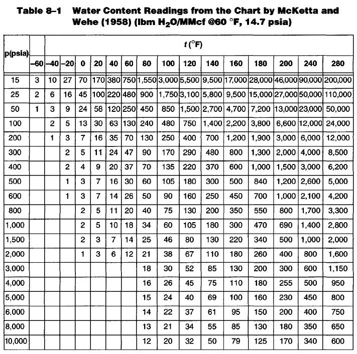
15 Natural Gas Water Content Water vapor content of natural gas can be determined from tables and chart at any temperature and pressure Example 1 Estimate water content of a natural gas at a pressure of 3,000 psia and temperature of 150 F. From Table 8.1 at 3000 psia: 140 (x1) 150 (x) 160 (x2) 85 (y1) y 130 (y2) y 85 ( )(130 85) ( ) y = 107 lbm/mmcf
16
17 Dehydration by Cooling The ability of natural gas to contain water vapor decreases as the temperature is lowered at constant pressure. During the cooling process, the excess water in the vapor state becomes liquid and is removed from the system. Gas compressors can be used partially as dehydrators. Because the saturation water content of gases decreases at higher pressure, some water is condensed and removed from gas at compressor stations by the compressor discharge coolers. Dehydration by Adsorption Adsorption is defined as the ability of a substance to hold gases or liquids on its surface. In adsorption dehydration, the water vapor from the gas is concentrated and held at the surface of the solid desiccant by forces caused by residual valiancy. Solid desiccants have very large surface areas per unit weight to take advantage of these surface forces. The most common solid adsorbents used today are silica, alumina, and certain silicates known as molecular sieves. Dehydration plants can remove practically all water from natural gas using solid desiccants. Because of their great drying ability, solid desiccants are employed where higher efficiencies are required.
18 Under normal operating conditions, the usable life of a desiccant ranges from one to four years. Solid desiccants become less effective in normal use due to loss of effective surface area as they age. Abnormally fast degradation occurs through blockage of the small pores and capillary openings from lubricating oils, amines, glycols, corrosion inhibitors, and other contaminants, which cannot be removed during the regeneration cycle. Hydrogen sulfide can also damage the desiccant and reduce its capacity.
19 Advantages of solid-desiccant dehydration The advantages of solid-desiccant dehydration include: lower dew point, essentially dry gas (water content less than 1.0 Ib/MMcf) can be produced higher contact temperatures can be tolerated with some adsorbents higher tolerance to sudden load changes, especially on startup quick startup after a shutdown high adaptability for recovery of certain liquid hydrocarbons in addition to dehydration functions Disadvantages of solid-desiccant dehydration Operating problems with the solid-desiccant dehydration include: space adsorbents degenerate with use and require replacement dehydrating tower must be regenerated and cooled for operation before another tower approaches exhaustion. The maximum allowable time on dehydration gradually shortens because desiccant loses capacity with use
20 Dehydration by Absorption One of the most common methods for removing the water from produced gas is glycol. There are four glycols that are used in removing water vapor from natural gas or in depressing the hydrate formation temperature. Ethylene glycol (EG) is not used in a conventional glycol dehydrator. The main use of EG in the dehydration of natural gas is in depressing the hydrate temperature in refrigeration units. Of the other three glycols, triethylene glycol (TEG) is the most commonly used glycol for dehydration of natural gas because of the advantages relative to diethylene glycol (DEG): TEG is more easily regenerated to a higher degree of purity Vapor losses are lower Operating costs are lower
21 Properties of Glycol OH OH H C C H H H
22 Glycol Dehydration Plant For more about Glycol dehydration, read the article at:

23 Schematic of a standard TEG Dehydration Plant Videos:
24 The feeding-in gas must be cleaned to remove all liquid water and hydrocarbons, wax, sand, drilling muds, and other impurities. These substances can cause severe foaming, flooding, higher glycol losses, poor efficiency, and increased maintenance in the dehydration tower or absorber. These impurities can be removed using an efficient scrubber, separator, or even a filter separator for very contaminated gases. Dew point depression of 40 o F to 140 o F can be achieved at a gas pressure ranging from 25 psig to 2500 psig and gas temperature between 40 o F and 160 o F. The dew point depression obtained depends on the equilibrium dew point temperature for a given TEG concentration and contact temperature. Increased glycol viscosity may cause problems at lower contact temperature. Thus, heating of the natural gas may be desirable. Very hot gas streams are often cooled prior to dehydration to prevent vaporization of TEG.
25 1 The feeding-in gas stream first enters the unit through an inlet gas scrubber to remove liquid accumulations. A two-phase inlet scrubber is normally required. If there is any liquid water in the gas stream, a three-phase inlet scrubber can be used to discharge the distillate and water from the vessel separately. A mist eliminator is normally in the scrubber to remove any entrained liquid particles from the gas stream leaving the top of the scrubber. 2 The wet gas is then introduced to the bottom of the glycol-gas contactor and allowed to flow upward through the trays, while glycol flows down through the column. The gas contacts the glycol on each tray and the glycol absorbs the water vapor from the gas steam. 3 The gas then flows down through a vertical glycol cooler, usually fabricated in the form of a concentric pipe heat exchanger, where the outlet dry gas aids in cooling the hot regenerated glycol before it enters the contactor. The dry gas then leaves the unit from the bottom of the glycol cooler. 4 The dry glycol enters the top of the glycol-gas contactor from the glycol cooler and is injected onto the top tray. The glycol flows across each tray and down through a downcomer pipe onto the next tray. The bottom tray downcomer is fitted with a seal pot to hold a liquid seal on the trays. 5 The wet glycol, which has now absorbed the water vapor from the gas stream, leaves the bottom of the glycol-gas contactor column, passes through a high-pressure glycol filter, which removes any foreign solid particles that may have been picked up from the gas stream, and enters the power side of the glycol pump.
26 6 In the glycol pump the wet high-pressure glycol from the contactor column pumps the dry regenerated glycol into the column. The wet glycol stream flows from the glycol pump to the inlet of the flash separator. The low-pressure flash separator allows for the release of the entrained solution gas, which must be used with the wet glycol to pump the dry glycol into the contactor. 7 The gas separated in the flash separator leaves the top of the flash separator vessel and can be used to supplement the fuel gas required for the reboiler. Any excess vent gas is discharged through a backpressure valve. The flash separator is equipped with a liquid level control and diaphragm motor valve that discharges the wet glycol stream through a heat exchange coil in the surge tank to preheat the wet glycol stream. If the wet glycol stream absorbs any liquid hydrocarbons in the contactor, it may be desirable to use a three-phase flash separator to separate the glycol from the liquid hydrocarbons before the stream enters the reboiler. Any liquid hydrocarbons present in the reboiler can cause undue glycol losses from the stripping still. The wet glycol stream leaves the heat exchange coil in the surge tank and enters the stripping still mounted on top of the reboiler at the feed point in the still. The stripping still is packed with a ceramic intalox saddle-type packing, and the glycol flows downward through the column and enters the reboiler. The wet glycol passing downward through the still is contacted by hot rising glycol and water vapors passing upward through the column. The water vapors released in the reboiler and stripped from the glycol in the stripping still pass upward through the still column through an atmospheric reflux condenser that provides a partial reflux for the column. The water vapor then leaves the top of the stripping still column and is released to the atmosphere.
27 Advantages of Glycol Dehydration Glycol dehydrators have several advantages including: low initial-equipment cost low-pressure drop across absorption towers makeup requirements may be added readily recharging of towers presents no problems the plant may be used satisfactorily in the presence of materials that would cause fouling of some solid adsorbents Disadvantages of Glycol Dehydration Glycol dehydrators present several operating problems including: Suspended matter, such as dirt, scale, and iron oxide, may contaminate glycol solutions. Overheating of solution may produce both low and high boiling decomposition products. The resultant sludge may collect on heating surfaces, causing some loss in efficiency, or, in severe cases, complete flow stoppage. When both oxygen and hydrogen sulfide are present, corrosion may become a problem because of the formation of acid material in the glycol solution.
28 Disadvantages of Glycol Dehydration contd Liquids such as water, light hydrocarbons, or lubrication oils, in inlet gas may require installation of an efficient separator ahead of the absorber. Highly mineralized water entering the system with inlet gas may, over long periods, crystallize and fill the reboiler with solid salts. Foaming of solution may occur with a resultant carry-over of liquid; the addition of a small quantity of antifoam compound usually remedies this problem. Some leakage around the packing glands of pumps may be permitted because excessive tightening of packing may result in the scouring of rods. This leakage is collected and periodically returned to the system. Highly concentrated glycol solutions tend to become viscous at low temperatures and, therefore, are hard to pump. Glycol lines may solidify completely at low temperatures when the plant is not operating. In cold weather, continuous circulation of part of the solution through the heater may be advisable. This practice can also prevent freezing in water coolers. To start a plant, all absorber trays must be filled with glycol before good contact of gas and liquid can be expected. This may also become a problem at low-circulation rates because weep holes on trays may drain solution as rapidly as it is introduced. Sudden surges should be avoided in starting and shutting down a plant. Otherwise, large carry-over losses of solution may occur.
29 Glycol Dehydrator Design Dehydrators with TEG in trays or packed-column contactors can be sized from standard models by using the following information: gas flow rate specific gravity of gas operating pressure Maximum working pressure of contact gas inlet temperature outlet gas water content required One of the following two design criteria can be employed: Glycol to water ratio (GWR). A value of 2 to 6 gal TEG/lbm H 2 O removed is adequate for most glycol dehydration requirements. Very often 2.5 to 4 gal TEG/lbm H 2 O is used for field dehydrators. Lean TEG concentration from reconcentrator. Most glycol reconcentrators can output 99.0 to 99.9% lean TEG. A value of 99.5% lean TEG is utilized in most designs.

30 Inlet scrubber

31

32 Contactor Contactor is designed for size (minimum diameter and height), gas capacity, rate of water removed, and number of trays (if it is trayed-type) If the gas is not standard or the operating temperature is different from the standard temperature, a correction should first be made as follows: The rate of water removed is: Both C wi and C wo can be determined from Table 8-1 based on operating pressure and the inlet and outlet temperatures

33 Contactor

34


35
36 Example Problem Design a trayed-type glycol contactor for a field installation to meet the following requirements: Gas flow rate: 12 MMscfd Gas specific gravity: 0.75 Operating line pressure: 900 psig Maximum working pressure of contactor: 1,440 psig Gas inlet temperature: T in = 90 o F Outlet gas water content: C wo = 6 Ib H 2 O/MMscf Design criteria: GWR = 3 gal TEG/lbm H 2 O with 99.5% TEG Solution Table 8-3 and Table 8-4 give C t = 1.01 and C g = 0.97 The gas capacity of contactor is calculated with: Table 8-7 gives contactor diameter: 30 in Table 8-1 gives water content of inlet gas: C wi = lbm/mmscf The required water content of outlet gas (6) determines the dew point temperature of the outlet gas through Table 8-1: T out = 24 o F Therefore, the dew point depression (T in -T out ) is Dt d = = 66 o F Glycol Water Ratio (GWR) = 3 gal TEG/lbm of water Therefore, number of trays = (from Table 8-9 or Figure 8-7) = ( )(12.25)/24 = lbm/h = MMscf/d
37 Class Exercise Design a glycol contactor for a field dehydration installation to meet the following requirements. Consider both trayed type and packed type contactors. Gas flow rate: 10 MMscfd Gas specific gravity: 0.65 Operating line pressure: 1,000 psig Maximum working pressure of contactor: 1,440 psig Gas inlet temperature: 90 o F Outlet gas water content: 7 Ib H 2 O/MMscf Design criteria: GWR = 3 gal TEG/lbm H 2 O with 99.5% TEG Calculate: 1. The diameter of contactor 2. The water content of the inlet gas 3. The rate of water removal 4. The number of trays or height of packing
38 Compression and Cooling
39 Introduction A gas compressor is a mechanical device that increases the pressure of a gas by reducing its volume. Compressors are similar to pumps: both increase the pressure on a fluid and both can transport the fluid through a pipe. Compressors are used for gases while pumps are used for liquids. As gases are compressible, the compressor also reduces the volume of a gas. Portable compressors were first utilized in the late 1880s in the mining industry to drill in-mine pneumatic percussion boreholes. Deep petroleum and natural wells were drilled utilizing portable air compressors in the 1920s. With the advent of natural gas and its use as a fuel, the necessity arose of transporting natural gas from the gas well to the ultimate consumer. A compressor was unnecessary as long as the pressure at the gas well could force the gas through the pipeline to its destination. Compressors became essential because gas transmission pipelines extended great distances from the gas field.
40 Uses of compressor Compressors used in the oil and gas industry are divided into six groups according to their intended service. These are: Flash gas compressors Gas lift compressors Reinjection compressors Booster compressors Vapor-recovery compressors Casinghead compressors Flash gas compressors Flash gas compressors are used in oil handling facilities to compress gas that is flashed from a hydrocarbon liquid when the liquid flows from a higher pressure to a lower pressure separator. Flash gas compressors typically handle low flow rates and produce high compression ratios.
41 Gas lift compressors Gas lift compressors are frequently used in oil handling facilities where compression of formation gases and gas lift gas is required. Gas lift compressor duty is frequently of low to medium throughput with high compression ratios. Many gas lift compressors are installed on offshore facilities. Reinjection compressors The reinjection of natural gas is employed to increase or to maintain oil production. Reinjection compressors can be required to deliver gas at discharge pressures in excess of 10,000 psi. Reinjection compressors also are used for underground storage of natural gas. Compressors, applied to these services, have large compression ratios, high power requirements, and low volume flow rates. Casinghead compressors Casinghead compressors are usually used with electric submersible pumps and rod pumps where formation gas is required to be separated downhole and then transported through the annulus. Often the compressor discharge is routed to either a booster or flash gas compressor or to a low-pressure gathering system. Like vapor recovery compressors, casinghead compressors operate with low suction pressures, high compression ratios, and low gas throughput rates.
42 Booster compressors Gas transmission through pipelines results in pressure drop because of friction losses. Booster compressors are used to restore the pressure drop from these losses. Selection of these compressors involves evaluating the economic trade-off of distance between pipeline boosting stations and life-cycle cost of each compressor station. Booster compressors also are used in fields that are experiencing pressure decline. Most centrifugal pipeline booster compressors are gas turbine driven, although the use of variable-speed motor drives is becoming more prevalent. Lowspeed integral gas engine reciprocating compressors also are used for gas transmission applications. Booster compressors typically are designed for high throughput rates and low compression ratio. Many booster applications can be configured in a single-stage centrifugal compressor. Vapor recovery compressors Vapor recovery compressors are used to gather gas from tanks and other lowpressure equipment in the facility. Often the gas from a vapor recovery compressor is routed to a flash gas, gas lift, or booster compressor for further compression. Low suction pressures, high compression ratios, and low gas throughput rates characterize these compressors.

43 Classification and types of compressor Compressors are classified into two major categories: Positive displacement compressors Dynamic or kinetic compressors

44 Positive displacement compressors Positive-displacement gas compressors work by forcing gas into a chamber whose volume is decreased to compress the gas. Piston-type compressors use this principle by pumping gas into a gas chamber through the use of the constant motion of pistons Positive displacement compressors are further divided into: Reciprocating Rotary types Reciprocating compressors are most commonly used in the natural gas industry. They are built for practically all pressures and volumetric capacities. 6-cylinder Reciprocating

45 Dynamic or kinetic compressors Dynamic compressors are continuous-flow machines in which a rapidly rotating element accelerates the gas as it passes through the element, converting the velocity head into pressure, partially in the rotating element and partially in stationary diffusers or blades. Dynamic compressors are further divided into: Centrifugal Axial-flow Mixed-flow types

46
47 Compressor Stations Compressor stations are facilities located along a natural gas pipeline which compress the gas to a specified pressure, thereby allowing it to continue traveling along the pipeline to the intended recipient. When natural gas does not have sufficient potential energy to flow, a compressor station is needed. Compressor stations enable the natural gas itself to travel through the pipelines which is crucial to the natural gas transport system. They also allow the gas to be rerouted into storage areas during periods of low demand. In addition, compressor stations are often accompanied by PIG launchers and PIG receivers which are vital for the maintenance and efficiency of the pipeline. They even include many safety features allowing the pipeline and station to function safely. The total number of compressor station facilities required to move product varies depending on the region and conditions. Generally compressor stations are located about every miles along the pipeline. Depending on the particular compressor station, its size, sophistication, and other factors, it may or may not be staffed with live, on-site personnel. Many modern compressor stations can be completely monitored and operated remotely.

48
49 Compressor Station Facilities Compressor Unit The compressor unit is the piece of equipment which actually compresses the gas. Some compressor stations may have multiple compressor units depending on the needs of the pipeline. The compressor unit is a large engine which typically works in one of three ways: Turbines with Centrifugal Compressors This type of compressor is powered by a turbine to turn a centrifugal compressor and is powered by natural gas from the pipeline itself. Electric Motors with Centrifugal Compressors This type of compressor also utilizes centrifugal compressors to compress the gas; however, instead of being powered by a natural gas fueled turbine, they instead rely on high voltage electric motors. Reciprocating Engine with Reciprocating Compressor This type of compressor uses large piston engines to crank reciprocating pistons located within cylindrical cases on the side of the unit. These reciprocating pistons compress the gas. These engines are also fueled by natural gas. Filters and Scrubbers Another component of compressor stations are filters and scrubbers which remove water, hydrocarbons, and other impurities from the natural gas.
50 Gas Cooling Systems When the natural gas is compressed its temperature rises. This is usually offset by having the gas travel through cooling systems which return it to temperatures that will not damage the pipeline. Mufflers Mufflers are typically present to help reduce the noise level at compressor stations. These are especially important if the compressor station is located near residential or other inhabited areas. PIG launchers and PIG receivers which are vital for the maintenance and efficiency of the pipeline. Safety features allowing the pipeline and station to function safely. Operating Pressure of the Pipeline There is a wide variation in the pressure within a given section of pipeline compared to other pipelines in other areas. The typical pressure may range anywhere from 200 psi (pounds per square inch) to 1,500 psi. This wide variation is also due to the type of area in which the pipeline is operating, its elevation, and the diameter of the pipeline. Because of the change in the environment, compressor stations may compress natural gas at different levels. Supply and demand can also be a factor at times in the level of compression required for the flow of the natural gas.
51 Design considerations Compressor stations can be designed so that they can be started, stopped and controlled by operators at a remote location, i.e., the next station or the main office. They can also be automatic where the compressor units can be started and stopped by pressure-sensitive devices. One such design would be three stations as a unit. The center station would be a manned engine type with unmanned gas turbine stations on either side of it to be controlled and maintained by the center station. There are at least two environmental problems with compressor stations noise and exhaust emissions. Noise can be controlled with mufflers. Exhaust emissions can be chemically controlled with wet scrubbers, but they are expensive. These problems should be solved at the time the compressors are purchased. Remote and unmanned stations should have an automatic fire control system with alarm to the nearest manned station.
52 Types of Compressor Stations Five types of compressor stations are generally utilized in the natural gas production industry: Field gas-gathering stations to gather gas from wells in which pressure is insufficient to produce at a desired rate of flow into a transmission or distribution system. These stations generally handle suction pressures from below atmospheric pressure to 750 psig and volumes from a few thousand to many million cubic feet per day. Relay or main line stations to boost pressure in transmission lines. They compress generally large volumes of gas at a pressure range between 200 and 1,300 psig. Repressuring or recycling stations to provide gas pressures as high as 6,000 psig for processing or secondary oil recovery projects. Storage field stations to compress trunk line gas for injection into storage wells at pressures up to 4,000 psig. Distribution plant stations to pump gas from holder supply to medium- or high-pressure distribution lines at about 20 to 100 psig, or pump into bottle storage up to 2,500 psig.
53 Compression theory Both positive displacement and dynamic compressors are governed by a few basic principles derived from the laws of thermodynamics. This section defines terminology and discusses the operating principles essential for understanding compressor design, operation, and maintenance. Compressor selection Proper selection of the compressor type and number of stages can be accomplished only after considering a number of factors. (For the purposes of this chapter, discussion is limited to centrifugal vs. reciprocating compressors.) Basic information needed for the proper selection includes: Volume and mass flow of gas to be compressed Suction pressure, Discharge pressure, Suction temperature Gas specific gravity, Available types of drivers Compression ratio Compression ratio, R c, is simply the absolute discharge pressure divided by the absolute suction pressure. Temperature ratio increases with pressure ratio. Temperature limits related to the mechanical design of compressors often will dictate the maximum pressure ratio that can be achieved in a stage of compression. In a design, if required overall compression ratio is greater than 6, then compression stages are needed.
54 Isentropic (adiabatic) compression An adiabatic process is one in which no heat is added or removed from the system. Adiabatic compression is expressed by where k = Cp/Cv = ratio of specific heats, dimensionless. Although compressors are designed to remove as much heat as possible, some heat gain is inevitable. Nevertheless, the adiabatic compression cycle is rather closely approached by most positive displacement compressors and is generally the base to which they are referred. When inlet temperature is known, the discharge temperature can be determined from the relationship Adiabatic efficiency is defined as the ratio of work output for an ideal isentropic compression process to the work input to develop the required head. For a given compressor operating point, the actual or predicted isentropic efficiency is S=suction, d=discharge

55 Polytropic compression A polytropic process is one in which changes in gas characteristics during compression are considered. Dynamic compressors generally follow the polytropic cycle as defined by the formula where n = polytropic exponent. The polytropic exponent n is experimentally determined for a given type of machine and may be lower or higher than the adiabatic exponent k. Because the value of n changes during the compression process, an average value is used. When inlet and discharge pressures and temperatures are known, the polytropic exponent can be determined from the relationship The efficiency of the polytropic compression process is given by


56 Power requirement The total power requirement of a compressor for a given duty is the sum of the gas power and the friction power. The gas power is directly proportional to head and mass flow and inversely proportional to efficiency. Mechanical losses in the bearings and, to a lesser extent, in the seals are the primary source of friction power. For centrifugal compressors, the gas power can be calculated as HP = gas power, horsepower m = mass flow rate, lbm/min H = compressor head, ft-lbf/lbm By considering mechanical efficiency, h m of compressor drivers, the brake horsepower, BHP is given by Example Natural gas is compressed by a reciprocating compressor from 60 F suction temperature and a compression ratio of 2. Calculate the discharge temperature assuming z is constant and k=1.3 T2 = 610 R = 150 F
57 Stage compression Number of stages of compression Using the specified overall pressure ratio and suction temperature (and an assumed efficiency), the discharge temperature for compression of gas with a known k value in a single stage can be estimated by η p = assumed polytropic efficiency, 0.72 to 0.85 for centrifugal compressors 1.00 for reciprocating compressors. If the single-stage discharge temperature is too high (typical limit is 300 to 350 F), it is necessary to configure the compression equipment in more than one stage. Calculating the compression ratio per stage does the evaluation of a multistage design. Pressure Ratio It is the ratio of the discharge pressure to the inlet pressure; in practice, pressure ratio seldom exceeds 4
58 Intercooling Where large pressure ratios are needed, splitting the compression duty into one or more stages with intercooling between stages can be the most energy efficient arrangement. The energy savings must be compared with the capital and maintenance investment necessary to provide the cooling. In addition to the thermodynamic benefit, intercooled compression systems result in lower discharge temperatures, which reduce the need for special compressor materials. 2-Stage compression arrangement
59 As gas is compressed by turbo, it heats up, not because of the heat of the turbocharger, but because as the air is pressurized, the air molecules are forced closer together and that results in an increase in energy. This energy manifests itself as heat. The function of an intercooler is to remove that heat from the intake charge. A well rounded design is one that removes heat efficiently, without creating a pressure drop that negates the gains from doing so. The main factors that come into play here are heat transfer area, internal flow area and internal volume. Heat transfer area is the total area of all of the fin packs and plates in the core. Internal
60 Heat Exchanger A heat exchanger is a unit where heat is transferred from a hot stream to a cold stream through a solid barrier (wall). Most chemical reactions are faster at higher temperatures and heat exchangers are frequently used to provide the heat necessary to increase the temperature of the reaction. Other everyday life example of heat exchangers: Radiator in a car Home heating and air conditioning system Refrigeration system cooling a can of soda Gas compressor intercooler To heat or cool a stream flowing from an item of equipment to another; a stream may be a liquid, a gas, or a multiphase mixture. Types of Heat Exchangers In heat exchangers, a large contact area is desired for good heat transfer. Shell and Tube A common heat exchanger is the shell and tube type where one part of the process flows through a tube and the other part around the shell. The shell and tube heat exchangers are one of the most popular types of exchanger due to the flexibility the designer has to allow for a wide range of pressures and temperatures.
 is used in both heat transfer and mass transfer applications such as in distillation, absorption, and extraction processes.")
61 There are two main principles for contacting streams in the shell and tube type: co-current flow and countercurrent flow. The countercurrent flow (shown in the figure) is used in both heat transfer and mass transfer applications such as in distillation, absorption, and extraction processes. The heat is transferred to incoming stream from the shell across the tube wall. The shell and tube exchanger consists of four major parts: Tube Stream Out Tubes Shell Stream In Shell Baffle Shell Stream Out Tube Stream In

62 U-tube exchangers. This is the cheapest of all removable bundle designs, but is generally slightly more expensive than a fixed tubesheet design at low pressures. However, it permits unlimited thermal expansion, allows the bundle to be removed to clean the outside of the tubes, has the tightest bundle to shell clearances and is the simplest design. A disadvantage of the U-tube design is that it cannot normally have pure counterflow and they are limited to even numbers of tube passes.
63 Design Options of Heat Exchangers Tubes may range in diameter from 12.7 mm (0.5 in) to 50.8 mm (2 in), but mm (0.75 in) and 25.4 mm (1 in) are the most common sizes. The tubes are laid out in triangular or square patterns in the tube sheets. The square layouts are required where it is necessary to get at the tube surface for mechanical cleaning. The triangular arrangement allows more tubes in a given space. The tube pitch is the shortest center-to-center distance between tubes. The tube spacing is given by the tube pitch/tube diameter ratio, which is normally 1.25 or Since a square layout is used for cleaning purposes, a minimum gap of 6.35 mm (0.25 in) is allowed between tubes Thermal Design The thermal design of a shell and tube exchanger is an iterative process which is normally carried out using computer programs from organizations such as the Heat transfer and Fluid Flow Service (HTFS) or Heat Transfer Research Incorporated (HTRI). However, it is important that the engineer understands the logic behind the calculation. In order to calculate the heat transfer coefficients and pressure drops, initial decisions must be made on the sides the fluids are allocated, the front and rear header type, shell type, baffle type, tube diameter and tube layout. The tube length, shell diameter, baffle pitch and number of tube passes are also selected and these are normally the main items that are altered during each iteration in order to maximize the overall heat transfer within specified allowable pressure drops.
64 The main steps in the calculation are given below: 1. Calculate the shell-side flow distribution 2. Calculate the shell-side heat transfer coefficient 3. Calculate tube-side heat transfer coefficient 4. Calculate tube-side pressure drop 5. Calculate wall resistance and overall heat transfer coefficient 6. Calculate mean temperature difference 7. Calculate area required 8. Compare area required with area of assumed geometry and allowed tubeside and shellside pressure drop with calculated values. 9. Adjust assumed geometry and repeat calculations until Area required is achieved within the allowable pressure drops. The cooling curves for the counter current and co-current flows are shown below. A corollary drawn from the second law of thermodynamics is that heat can only be transferred from a hotter body to a colder body. For heat exchangers design, this means that the higher cooling curve and the lower one cannot intercept. When this condition is satisfied, the pairing of a heating and cooling curve is said to be feasible.
65 Temperature DT 1 T h,in T c,out cold hot DT 2 T h,out T c,in T h,in T c,in hot DT 1 DT 2 cold T h,out T c,out c,in c,out h,in Countercurrent flow h,out h,in Co-current flow h,out c,out c,in The rate of heat transfer is proportional to: i) the temperature difference between the hot streams and the incoming streams ii) the total surface area of the tubes The heat transfer from a hot to a cold side is expressed as: Q = UADT DT = T h T c = change in temperature U = heat transfer coefficient (note: it is not internal energy) A = surface area of the heat transfer
66 For countercurrent flow, DT 1 = T h,in T c, out ; DT 2 = T h,out T c,in For co-current flow, DT 1 = T h,in T c, in ; DT 2 = T h,out T c,out In the general case, DT varies with position in the heat exchanger. The maximum heat that can be transferred occurs when the heating and cooling curves either (a) intercept or (b) become tangent (flatten out) within the exchanger. There are 2 values of DT. The correct mean value of DT is expressed as (logarithm mean temperature difference): The heat transfer Q = UADT lm F (F=1 for ideal cases) The energy balance should help to calculate all the temperature variables Assuming steady state flow On cold side H c,out H c,in = Q Q = m c c p,c (T c,out T c,in ) c p,c = specific heat capacity of cold stream Q = heat supplied by the hot side On hot side H h,out H h,in = -Q Q = m h c p,h (T h,in T h,out ) c p,h = specific heat capacity of hot stream Q = heat supplied to the cold side
67 Example 1: Heat loss through window Indoor air with constant temperature of 23 C exchanges heat through a glass window with outside air at constant temperature of -2 C. The heat transfer coefficient is 3 W/m 2 K and the surface area of the window is 4 m 2. Calculate the heat loss through the window. Q = UA (T h T c ) = 3(4)( ) = 300 W Example 2: Countercurrent flow heat exchanger A hot stream with mass flow of 1 kg/s, heat capacity of 4 kj/kg K, and inlet temperature of 360 K is to be cooled to 330 K by heat exchange with a cold stream of mass flow of 2 kg/s, heat capacity of 3 kj/kg K, and an inlet temperature of 320 K. The overall heat transfer coefficient is 500 W/m2. Calculate the area of the heat exchanger when ideal countercurrent flow is assumed. m h = 1 kg/s T h,in = 360 K c p,h = 4 kj/kgk hot Q m h = 1 kg/s T h,out = 330 K c p,h = 4 kj/kgk m c = 2 kg/s T c,out c p,c = 3 kj/kgk cold m c = 2 kg/s T h,in = 320 K c p,c = 3 kj/kgk
68 First we have to find Q and T c,out On the hot side, Q = m h c p,h (T h,in T h,out ) = 1(4)( ) = 120 kw On the cold side, Q = m c c p,c (T c,out T c,in ) 120 = 2(3)( T c,out 320) => T c,out = 340 K For countercurrent flow, DT 1 = T h,in T c, out = = 20 DT 2 = T h,out T c,in = = 10 DT lm = (20 10)/ln2 = 14.4 K The heat transfer Q = UADT lm F = 500(A)(14.4) A = 16.6 m 2 (F=1 for ideal cases)
69 Heat Removed by Intercoolers DH = mc p (T 2 -T 1 ) For natural gas, c p = 0.56 Btu/lbm o F, c v = 0.44 Btu/lbm o F, k =1.27 Mass flow rate = rq By law of conservation of mass, mass flowrate is constant across compressors but volume flowrate changes Density at any section can be calculated from r 2. 7 p zt
70 Example In a 4 stage compressor, the suction pressure at the first and third stage are 100 psi and 900 psi. Intercoolers cool the gas back to 60 F. Calculate stages 1 and 2 discharge volume flowrate and the amount of heat removed by each intercooler per day for a gas flowrate of 900 Mscf/d at stage 1 inlet. Gas specific gravity is 0.65 and suction temperature is 60 F. k=1.3. P 1s =100 P 1d =300 P 2s =300 P 2d =900 P 3s =900 P 3d = T 1s =60 T 1d =210 T 2s =60 T 2d =210 T 3s =60 T 3d =210 R c = (900/100) = 3 P 1s =100, P 1d =300 T 1d = 670 R = 210 F 100, 60 (130) 300, 210 (2500) 300, 60 (47) 900, 210 (1925) 900, 60 (19)
71 From Brill-Beggs, P 1s =100 psi, T 1s =60 F, z 1s = P 1d =300 psi, T 1d =210 F, z 1d = p 2.7*100*0.65 r1s zt *520 m 1s = rq = * = lbm/d m 1d = m 2d = m 3d = m 1s = lbm/d P 2d =900, T 2d =210, z 2d = P 3d =2700, T 3d =210, z 3d = P 4d =8100, T 4d =210, z 4d = lbm/ft 3 r 1d = 2.7x300x0.65/0.9796/670 = Q 1d = m 1d /r 1d = / = 384,654 scf/d r 2d = 2.7x900x0.65/0.9405/670 = Q 2d = m 2d /r 2d = / = 123,100 scf/d r 3d = 2.7x2700x0.65/0.8825/670 = Q 3d = m 3d /r 3d = /8.014 = 38,503 scf/d r 4d = 2.7x8100x0.65/1.2369/670 = Q 4d = m 4d /r 4d = /8.014 = 17,988 scf/d
72 Introduction A gas compressor is a mechanical device that increases the pressure of a gas by reducing its volume. Compressors are similar to pumps: both increase the pressure on a fluid and both can transport the fluid through a pipe. Compressors are used for gases while pumps are used for liquids. As gases are compressible, the compressor also reduces the volume of a gas. Portable compressors were first utilized in the late 1880s in the mining industry to drill in-mine pneumatic percussion boreholes. Deep petroleum and natural wells were drilled utilizing portable air compressors in the 1920s. With the advent of natural gas and its use as a fuel, the necessity arose of transporting natural gas from the gas well to the ultimate consumer. A compressor was unnecessary as long as the pressure at the gas well could force the gas through the pipeline to its destination. Compressors became essential because gas transmission pipelines extended great distances from the gas field.
73 Uses of compressor Compressors used in the oil and gas industry are divided into six groups according to their intended service. These are: Flash gas compressors Gas lift compressors Reinjection compressors Booster compressors Vapor-recovery compressors Casinghead compressors Flash gas compressors Flash gas compressors are used in oil handling facilities to compress gas that is flashed from a hydrocarbon liquid when the liquid flows from a higher pressure to a lower pressure separator. Flash gas compressors typically handle low flow rates and produce high compression ratios.
74 Removal of Acid Gases The H 2 S and CO 2 in natural gas wellstreams are called acid gases because they form acids or acidic solutions in the presence of water. They have no heating value but cause problems to systems and the environment. H 2 S is a toxic, poisonous gas and cannot be tolerated in gases that may be used for domestic fuels. H 2 S in the presence of water is extremely corrosive and can cause premature failure of valves, pipeline, and pressure vessels. It can also cause catalyst poisoning in refinery vessels and requires expensive precautionary measures. Most pipeline specifications limit H 2 S content to 0.25 g/100 ft 3 of gas (about 4 ppm) Carbon dioxide is not as bad as H 2 S and its removal is not always required. Removal of CO 2 may be required in gas going to cryogenic plants to prevent CO 2 solidification. Carbon dioxide is also corrosive in the presence of water. Most treating processes that remove H 2 S will also remove CO 2. Therefore, the volume of CO 2 in the wellstream is added to the volume of H 2 S to arrive at the total acid-gas volume to be removed. The term sour gas refers to the gas containing H 2 S in amounts above the acceptable industry limits. A sweet gas is a non-h 2 S-bearing gas or gas that has been sweetened by treating. Some processes used for removing acid gases from natural gas are briefly described below.
75 Sour gas sweetening Sour natural gas compositions can vary over a wide concentration of H 2 S and CO 2 and a wide concentration of hydrocarbon components. If the H 2 S content exceeds the sales gas specification limit, the excess H 2 S must be separated from the sour gas. The removal of H 2 S from sour gas is called sweetening. The selected process must be cost effective in meeting the various specifications and requirements.
76 Sweetening solvents The desirable characteristics of a sweetening solvent are: Required removal of H 2 S and other sulfur compounds must be achieved. Pickup of hydrocarbons must be low. Solvent vapor pressure must be low to minimize solvent losses. Reactions between solvent and acid gases must be reversible to prevent solvent degradation. Solvent must be thermally stable. Removal of degradation products must be simple. The acid gas pickup per unit of solvent circulated must be high. Heat requirement for solvent regeneration or stripping must be low. The solvent should be noncorrosive. The solvent should not foam in the contactor or still. Selective removal of acid gases is desirable. The solvent should be cheap and readily available. Unfortunately, there is no one solvent that has all the desirable characteristics. This makes it necessary to select the solvent that is best suited for treating the particular sour gas mixture from the various solvents that are available. The sour natural gas mixtures vary in H 2 S and CO 2 content and ratio
77 Main sweetening solvents
78 Operating problems The main problems that can be encountered in the operation of sour gas treating facilities using chemical solvents are as follows: 1. Failure to meet H 2 S specification for sales gas: treated gas that does not meet the H 2 S specifications is not admitted into the sales-gas transmission lines. Difficulty in meeting the sweet gas specification may be the result of poor contact between the gas and the solvent, which may in turn be caused by foaming or mechanical problems in the contacting equipment 2. Solution foaming in the contactor or regenerator: occurs when gas is mechanically entrained in liquid as bubble. The best way to reduce the propensity for foaming is to ensure that the sour gas entering the contactor is clean, free of condensed liquids, and that the solution is cleaned up by mechanical and carbon filtration 3. Corrosion in pipes and vessels: corrosion is common in most amine plants; it is necessary to control the corrosion rate by the addition of corrosion inhibitor and by use of stainless steel in certain pieces of process equipment. As compared with CO 2 and H 2 S mixtures, corrosion rates in amine systems, especially MEA systems, generally increase with: increasing temperature, increasing amine concentration, increasing mole loadings, pure acid gas 4. Solvent losses: solvent losses in gas treating systems can occur because of vaporization, entrainment, degradation, mechanical losses. Solvents used in gas treating, like any other liquids, have a vapor pressure that increases with temperature.
79 Iron-Sponge Sweetening The iron-sponge sweetening process is a batch process with the sponge being a hydrated ferric oxide (Fe 2 O 3 ) supported on wood shavings. The reaction produces ferric sulfide (Fe 2 S 3 ) and water. Fe 2 O 3 + H 2 S Fe 2 S 3 + H 2 O Balance the equation The ferric oxide is present in a hydrated form. The reaction does not proceed without the water of hydration. The reaction requires the temperature be below approximately 120 o F or a supplemental water spray. Regeneration of the bed is sometimes accomplished by the addition of air continuously or by batch addition. The regeneration reaction is Fe 2 S 3 + O 2 Fe 2 O 3 + S Balance the equation The number of regeneration steps is limited due to the sulfur remaining in the bed. Eventually the beds have to be replaced.
80 Alkanolamine Sweetening Alkanoalamine includes monoethanoalamine (MEA), diethanoalamine (DEA), and triethanoalamine (TEA). They are used to remove acid gases (H 2 S and CO 2 ) from other gases and are particularly adapted for obtaining the low acid gas residuals that are usually specified by pipelines. MEA was the earliest amine used for sweetening sour gas. It is a stronger base than DEA and also has a higher vapor pressure than DEA; therefore, vapor losses are higher than for DEA. The alkanolamine process is not selective and must be designed for total acid-gas removal, even though CO 2 removal may not be required. Typical reactions of acid gas with MEA are absorbing and regenerating. Absorbing reactions are: MEA + H 2 S MEA[H + ] + HS - MEA + H 2 O + CO 2 MEA[H + ] + HCO kj/kg of CO2

81
82 Glycol/Amine Process The glycol/amine process uses a solution composed of 10% to 30% weight MEA, 45% to 85% glycol, and 5% to 25% water for the simultaneous removal of water vapor, H 2 S, and CO 2 from gas streams. The advantage of the process is that the combination dehydration and sweetening unit results in lower equipment cost than would be required with the standard MEA unit followed by a separate glycol/amine glycol dehydrator. The main disadvantages of the glycol/amine process include increased vaporization losses of MEA due to high regeneration temperatures, corrosion problems in the operating units, and limited applications for achieving low dew points. Sulfinol Process The sulfinol process uses a mixture of solvents allowing it to behave as both a chemical and physical solvent process. The solvent is composed of sulfolane, diisopropanolamine (DIPA), and water. The sulfolane acts as the physical solvent, while DIPA acts as the chemical solvent. The main advantages of sulfinol are low solvent circulation rates; smaller equipment and lower plant cost; low heat capacity of the solvent; low utility costs; low degradation rates; low corrosion rates; low foaming tendency; high effectiveness for removal of carbonyl sulfide, carbon disulfide, and mercaptans; low vaporization losses of the solvent; low heat-exchanger fouling tendency; and nonexpansion of the solvent when it freezes. Some of the disadvantages of sulfinol include absorption of heavy hydrocarbons and aromatics, and expense.
83 Hot potassium carbonate (K 2 CO 3 ) (Hot Pot) The potassium carbonate process was developed for removing CO 2 from manufactured gas. It reacts with both acid gases. Because the contacting of the sour gas occurs at very high temperatures, such as 195 to 230 F in this process, it is sometimes referred to as the hot pot process. It requires lower heat input for regeneration and is therefore somewhat less costly to operate than some amine processes. Also, no heat exchanger is required in the regeneration equipment. The process has difficulty in meeting the H 2 S specification of the treated gas if the H 2 S/CO 2 ratio is not extremely small. This process is significant for treating gas with a large concentration of CO 2. The chemistry of the process can be enhanced by the addition of various catalysts, and this has resulted in the process being referred to by various trade names.
84 Natural Gas Liquids The term 'Natural gas liquids' includes both the 'condensed' gaseous liquids captured at natural gas plants, and the 'normally liquid' lease condensate, often removed right at the wellhead. The gaseous liquids are usually made up of both: (i) lighter hydrocarbons, predominantly ethane, and propane, and (ii) heavier hydrocarbons, such as pentane and heavier (condensates). Ethane, propane, normal butane, isobutane and (as the product is commonly called in the U.S.), natural gasoline are all found in natural gas, but are liquid hydrocarbon molecules suspended within gas. This is equally true for lease condensates, hence the classification of lease condensates as NGLs in international markets. Market Definitions NGLs are liquid hydrocarbons suspended as particles in gas, under conditions of subterranean pressure and temperature. As noted above, in the U.S. the term NGL is usually reserved for these products produced through some form of processing (natural gas processing plants or refineries), while in international markets it also includes field or lease condensates.
85 Y-Grade, also called mixed NGLs or raw make is an unfractionated blend of the various purity products (see definition below) that make up the NGL product family. A Y-grade stream is typically produced by a natural gas processing plant and transported by pipeline to a central fractionation facility to be split into purity products. NGL Purity Products As this term is used in the U.S., the five purity NGL products are ethane (C2), propane (C3), normal butane (NC4), isobutane (IC4) and natural gasoline (C5+). The numbers indicate how many carbon atoms are contained in each NGL molecule. While butane and isobutane both have four carbon atoms, they differ somewhat in molecular structure. As a general rule, when at least 90% of the NGL stream has only one type of product, this NGL, whether ethane or butane, is defined as a purity product. Liquefied Petroleum Gas, or LPG, is a subset of the NGL family. In the U.S. the term includes propane, normal butane and isobutane and is often associated with refinery production and demand for these products. The term is also used to refer to the international trade for propane and butanes. Pentane+ or C5+ designations include the products that we also call condensates.
86 Heavier NGLs: In the US market, the term Heavy NGLs refers to natural gasoline and butane/isobutane, but this definition is not universal and certainly can be misleading. The only heavy NGL that can be separated, stored and transported without special containment is condensate (natural gasoline), a point which we will detail further below. The term Heavy NGLs is rarely used in foreign NGL markets, and when it is occasionally used, it refers solely to condensate. Ethane/Propane Mix: In the US market, ethane and propane are sometimes sold as a mixed stream for use as a petrochemical feedstock. The most common is called E/P Mix, consisting of 80% ethane/20% propane. In some cases the buyers want a custom blend that differs in the proportion of these two NGLs. E/P Mix is sold in European NGL markets and is the basis of Mideast Gulf ethylene cracker feedstock supply, but is virtually unknown in Asia.
87 Note that most NGLs originate from gas production, whether associated with crude or solely on its own non-associated gas production. When NGLs are contained within a gas stream, it is said that they are in vapor phase. All natural gas contains some NGLs. Sometimes there are enough NGLs to be recovered economically, sometimes not. Sometimes NGLs must be removed (whether economic or not) for the residue natural gas to meet BTU and other specifications for the take-away natural gas pipeline or LNG liquefaction facility. Regardless, for natural gas produced at the wellhead to be sold and transported in pipeline systems, various impurities like sulfur and water must be removed. When required by downstream specifications, or economically advantageous or both, the NGLs are separated from the gas in a natural gas processing plant. The mixed stream or Y-grade NGLs are then transported to a fractionator for separation into purity products. That fractionator may be at the processing plant location, but in the U.S. is usually some distance away. As discussed on many occasions in RBN blogs, by far the largest NGL fractionation center in the U.S. is at Mont Belvieu, Texas.

88
89 Processing Natural Gas Liquids Liquefied Petroleum Gas (LPG) The smaller molecules such as ethane, ethylene, propane, butane, butylene, isobutane, and isobutylene can be retrieved from the natural gas stream and converted into liquids at the natural gas processing plants by methods such as freezing and pressurizing. For example, the second smallest molecule, propane, can be turned into a liquid at -42 o C. The liquefied gases may be mixed together and taken to a specialist plant for fractionation, where the individual products are split out and sold separately. Ethane is an important feedstock in the chemical industry, making, amongst other things, ethylene. Propane is used in home heating and cooking. Butane is used as a gasoline additive as an oxygenate to reduce pollution. If not sold separately, the fractionates can be mixed together to form 'liquefied petroleum gases', or LPG. This blend has to remain pressurized to be liquid. This gas can be held in relatively thin walled bottles, so is sold worldwide for both domestic cooking as 'bottled gas' and as a transport fuel.
90 Some heavier hydrocarbons with more hydrogen atoms, such as hexane and heptane, can also be recovered from the fractionation of the gas stream. They can be used to 'make' gasoline, but have to be blended with other liquid hydrocarbons from distillation of crude oil in order to be useful. These heavier gaseous natural gas liquids cannot be counted as 'oil equivalent' by themselves - they depend on crude oil to become useful. Natural Gasoline The heavier hydrocarbons that are liquid at normal temperatures are often called 'lease condensate', 'natural gas condensate', 'natural gasoline', or 'casinghead gasoline'. A typical 'natural gas liquids' breakdown would be about 83% gaseous liquids, and 17% natural gasoline (it varies, and can be as much as 22%). The production of plant condensate, a.k.a. natural gasoline, is increasing along with the yield of all other products from natural gas processing plants. Clearly this is an opportunity for new market development, and the business community is hard at work coming up with concepts, projects and proposals to use all of this material in the U.S. and in export markets. But there is a problem. Condensate markets in different geographies seem to have little in common with each other. One term can have several meanings. One meaning can be ascribed to several terms.
91 Liquefied Natural Gas As concern over environmental problems grows worldwide, there is increasing demand for natural gas as an energy source with a smaller environmental impact (lower CO 2 emissions) than oil or coal. With this growth in demand, LNG plants are receiving much attention. Plant production capacity, which was initially about 1 million tons/year, has reached 7.8 million tons/year, and the capacities of the various process gas compressors used in the plant are also increasing. At the same time, there is also growing interest in the development of small and mid-sized LNG plants as a means of making effective use of unused gas fields. At an LNG plant, the liquid components (condensate) are removed from the natural gas that was produced from the gas field. The natural gas then passes through acid gas (hydrogen sulfide, carbon dioxide) removal equipment, mercury removal equipment, dehydration equipment, and NGL removal equipment, and is then liquefied by liquefaction equipment where its volume is reduced by a factor of 600. Afterwards, the natural gas is stored in an LNG tank. Recently, in addition to the conventional "On-shore" LNG Plant, new technologies have created Floating LNG (F-LNG) which allows for offshore liquefaction. Various process gas compressors and drive equipment are used in these gas processing and liquefaction processes.
92 Production of LNG Cooling natural gas to about -260 F at normal pressure results in the condensation of the gas into liquid form, known as Liquefied Natural Gas (LNG). LNG can be very useful, particularly for the transportation of natural gas, since LNG takes up about one six hundredth the volume of gaseous natural gas. While LNG is reasonably costly to produce, advances in technology are reducing the costs associated with the liquification and regasification of LNG. Because it is easy to transport, LNG can serve to make economical those stranded natural gas deposits for which the construction of pipelines is uneconomical. LNG, when vaporized to gaseous form, will only burn in concentrations of between 5 and 15 percent mixed with air. In addition, LNG, or any vapor associated with LNG, will not explode in an unconfined environment. Thus, in the unlikely event of an LNG spill, the natural gas has little chance of igniting an explosion. Liquification also has the advantage of removing oxygen, carbon dioxide, sulfur, and water from the natural gas, resulting in LNG that is almost pure methane.

93 Transportation of LNG LNG is typically transported by specialized tanker with insulated walls, and is kept in liquid form by autorefrigeration, a process in which the LNG is kept at its boiling point, so that any heat additions are countered by the energy lost from LNG vapor that is vented out of storage and used to power the vessel. LNG that is imported to the United States comes via ocean tanker. The U.S. gets a majority of its LNG from Trinidad and Tobago, Qatar, and Algeria, and also receives shipments from Nigeria, Oman, Australia, Indonesia, and the United Arab Emirates.

94

95 LNG Equipment