Infiltration. ro ock and soil. Soil. Unsa aturated Zone. Hydraulic properties? Rock. soil. pores filled with air and water
|
|
|
- Crystal Rose
- 5 years ago
- Views:
Transcription

1 Proprietà idrauliche in condizione di saturazione variabile: come misurarle in laboratorio e in campo? Maria Clementina Caputo


2 Unsaturated zone measurement purposes To measure, predict, and understand the flow of water through soil and rock, between the land surface and the water table in order: Infiltration ro ock and soil soil to quantify hazards for groundwater from toxics to assess aquifer recharge rates to improve irrigation management to improve agricultural practices Rock pores filled with air and water Soil Hydraulic properties? Unsa aturated Zone
3 Unsaturated zone parameters θ( ψ) θ t = z K ( ) ψ θ 1 z? K ( ψ) K( θ) θm = P Pd P d θv = Vw V θv = ρb ρw θ m
 but have been little-used in rock.")

4 Problem Many unsaturated-zone methods have been developed for use in soils (for example, MoSA has 1692 pages) but have been little-used in rock. Soil Rock Friable Compressible Can be trimmed and cored with hand tools Easy to sample in the field Rigid matrix Incompressible Cannot be easily trimmed and cored in the lab Hard to sample in the field
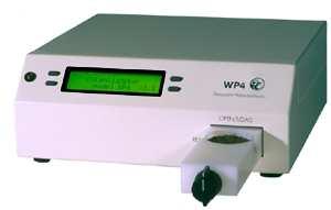
5 Centrifuge method Psycrometro WP4 Suction table method Laboratory tests Wind s method

6 GPR method Field tests Electrical Resistivity Profiles Infiltrometer test


7 Rocks used in the laboratory tests Calcarenite, a sedimentary rock of marine origin Widely found in the Mediterranean basin From Apulia in Southern Italy Lithotype A medium-fine grains grainstone type grain-sustained texture Lithotype B biocalcarenite medium-coarse grains packestone type grain-sustained texture Lithotype M fine grains wackestone type mud-sustained texture
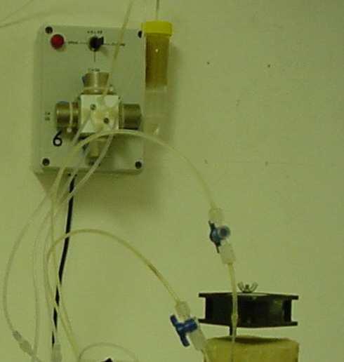
8 Wind s method (Caputo et al., IGEA, 20, 49-58, 2005) Allows simultaneous determination of θ(h) and K(θ) assuming: porous media must be homogeneous water flow is expressed with Darcy s law potentials other than matric are neglegible; sample is considered to have discrete compartments in the center of which tensiometers are placed; water content variation is linear within each compartment. fan tensiometers sample load cell
9 Wind s experimental procedures 1) The measured matric potential values are converted to water content using an initial water retention curve. 2) These are compared with the measured water content. 3) If there are differences between the measured and estimated values, new parameters of the retention curve are computed, and the calculation is iterated until discrepancies are tolerable. 4) The measured potentials and calculated water contents are used to calculate the hydraulic conductivity, K(θ).
10 Difficult installation of the tensiometer in the rock sample. First experimental data of calcarenite hydraulic properties; Lithotypes A and B have greater hydraulic conductivity than M; For h > 0.2 m the water contents of lithotype M exceeds that of A and B between which the differences are negligible. k (m/s) 1,E-03 Lythotipe A 1,E-04 Lythotipe B 1,E-05 Lythotipe M 1,E-06 1,E-07 1,E-08 1,E ,1 0,2 0,3 0,4 0,5 0,6 θ (m( 3 m )
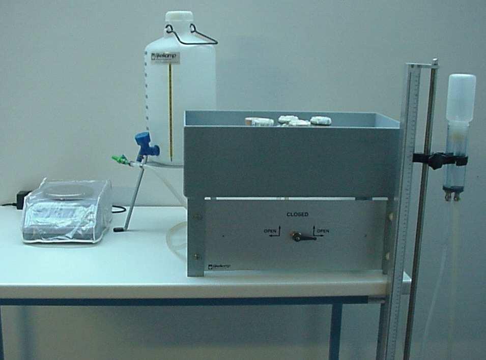
11 Suction table method The suction table allows measurement of water retention characteristics from close to saturation to a minimum pressure head around -100 cm. The apparatus is made of: box filled with a layer of very fine synthetic sand, in which is a drainage system; supply bottle; sliding measuring stand with suction regulator used to apply different matric potential.
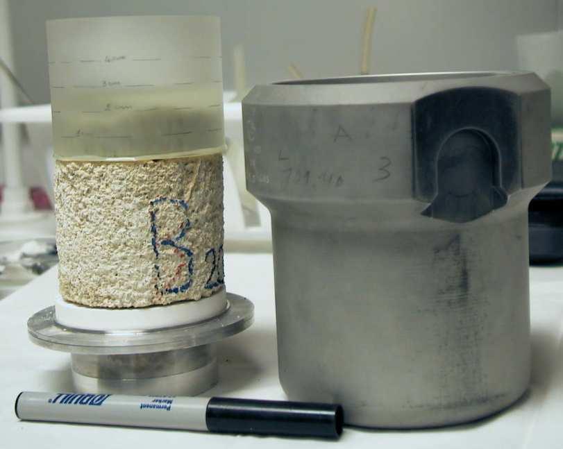
12 Experimental procedure Thin layer of epoxy resin that sealed the sample after the hardening. 1. The saturated core samples are rested on a porous layer subjected to known potential. 2. A series of static equilibria is established between the water in the samples and a free body of water contained in the suction control system. 3. At each steady state condition volumetric water content, θ, and the related matric potential, h, are determined.
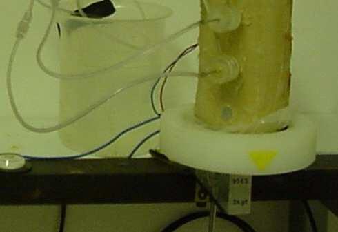
13 Quasi Steady Centrifuge (QSC) method (Caputo & Nimmo, Water Resouces Research, 41 (10) 1-5, 2005) It derives from the steady-state centrifuge (SSC) method, which has a steady flow of water within a sample in a centrifuge, applied by either a constant head (Nimmo et al., 1987) or a metering pump If suitable conditions develop within the (Conca and Wright, 1998). sample, K(θ) can be computed using the centrifugal form of Darcy s law. q dh 2 = K( θ ) ρω r dr
14 Experimental apparatus Apparatus in the centrifuge bucket includes a flow-controlling reservoir above the sample, nearly filled with water at the start of each run. Sealed to this reservoir is a thin, flexible material, which supports a cake of fine granular material that controls the flow rate into the sample giving different flow rates for measuring different points on the K(θ) curve.
15 Lithotypes A and C have behavior similar to that of lithotypes B and M but showing greater hydraulic conductivity; Different samples of the same lithotype show same experimental values the method works well. θ (m 3 m -3 ) Lythotipe A Lythotipe M Lythotipe C Lythotipe B Lythotipe M Lythotipe C h (m) 1.E-03 1.E-04 1.E-05 k (m/s) 1.E-06 1.E-07 1.E-08 1.E-09 1.E-10 1.E-11 Lythotipe A Lythotipe B Lythotipe M Lythotipe M Lythotipe C Lythotipe C θ (m ( m ) The QSC method extends to lower values of hydraulic conductivity and to drier range of water retention.
16 Results Suction table method gives good information only in the wet range of water retention where Wind s method does not work well. θ (cm 3 cm -3 ) Suction table method Wind s method QSC method Fitted data by van Genucthen model IhI (cm) The use of all the experimental data allows a water retention curve to describe the retention for a wider range of matric potential, h.


17 visibly fractured limestone Infiltrometer test A large ring infiltrometer of 2 m diameter and 30 cm height, yielded infiltration data representative of the anisotropic and heterogeneous rock. thin furrow, 2 cm deep, hollowed in the limestone and sealed with gypsum cm limestone without visible fractures cm
18 Electrical Resistivity Profiles Pressure probe to monitor the water level decrease Subsurface electrical resistivity measurements as an indicator of water infiltration/redistribution in the rock.
19 Electrical Resistivity Profiles (Caputo et al., Environmental Earth Science, e, 60: , 590, 2010; Caputo et al., Fresenius Environmental Bulletin,, 9a: , 1970, 2010; Masciopinto & Caputo, Vadose Zone Journal, accepted for publication, 2011) To interpret the results of falling head infiltrometer test, it was considered the simplified equation from Nimmo et al. (2009): K fs = L t G ln L G L G + λ + D o + λ + D Kfs (LT-1) is the field-saturated hydraulic conductivity t is the time, Do and D are the initial and final ponded depths, respectively, LG = C1d + C2b is the ring-installation scaling length, with and as recommended values for C1 and C2 while d and b are the ring insertion depth and ring radius, respectively, λ is an index of how strongly water is driven by capillary forces in a particular medium.
20 Electrical Resistivity Profiles (Caputo et al., Environmental Earth Science, e, 60: , 590, 2010; Caputo et al., Fresenius Environmental Bulletin,, 9a: , 1970, 2010; Masciopinto & Caputo, Vadose Zone Journal, accepted for publication, 2011) To interpret the results of falling head infiltrometer test, it was considered the simplified equation from Nimmo et al. (2009): effective infiltration length (cm) K fs = L t G ln Kfs (LT-1) is 3 the field-saturated hydraulic conductivity y = 5,608E-04x + 7,450E-01 L G L G R 2 = 9,797E-01 + λ + D o + λ + D t is the time, 2 Do and D are the initial and final ponded depths, y = 6,583E-04x respectively, + 1,704E-01 LG = C1d + C2b is the ring-installation scaling length, R 2 with = 9,896E and as recommended values for 1 C1 and C2 while d and b are the ring insertion depth and ring radius, respectively, y = 1,223E-03x λ is an index of how Rstrongly 2 = 8,456E-01 water is driven by capillary forces in a particular medium. 0 b) time (s)


21 Comparison between ERT and modeling results Time from start of infiltration 30 min min min Wet fractured rock Dry fractured rock ERI observations 1.0 Wet Simulated water content Dry
22 Considerations The electric resistivity profiles coupled with infiltration test are a useful tool in the study of unsaturated flow in rocks like limestone, in which no others devices (TDR, tensiometer, etc.) can be used. Allow monitoring of infiltration and redistribution The in situ experimental apparatus works well on limestone outcrops. of water in the rocky subsurface. Good sealing with gypsum of the ring installed into the incised furrow.


23 GPR method Ground penetrating radar used in a quarry of calcarenite with the aim to produce a map of water content at different depth of the subsurface rocky.
24 Conclusions on laboratory methods Wind s and suction table methods, set up for soil, work well also with rock even if they allow measurements in a small range of water retention curve close to saturation. Some complications are related with the procedures of preparation samples (insertion of tensiometers in the rock core sample and isolation of its lateral surface). The Quasi-steady centrifuge method is the most promising one because potentially allows to explore the entire water retention curve and, simultaneously, to measure hydraulic conductivity.
25 In the future To improve the QSC method for a standardized experimental procedure. To find different granular materials for measuring a wired range of hydraulic properties
26 Conclusions on field methods Combining an infiltrometer test and ERP is a good way to study unsaturated behavior in anisotropic and heterogeneous rock Geophysical techniques represents a challenge of upscaling unsaturated hydraulic properties. In the future To calibrate geophysical techniques with direct field measurements using standard devices for soil (tensiometers) and new devices based on electrical impedance (EUREKA Project). To improve the field apparatus in order to reduce measurement uncertainty and facilitate infiltrometer installation. Thank you for your attention