Separations Equipment
|
|
|
- Cathleen Russell
- 5 years ago
- Views:
Transcription

1 Separations Equipment Jack Law Idaho National Laboratory Introduction to Nuclear Fuel Cycle Separations Vanderbilt University December 17, 2008
2 Outline Introduction Role of separations equipment in the nuclear fuel cycle Solvent extraction basic principles p Solvent Extraction Equipment Mixer-settlers Columns Centrifugal contactors Comparison of Equipment Summary
3 Introduction Liquid-liquid extraction is widely used in fuel cycle facilities in the nuclear industry France United Kingdom Japan Russia Previously in the United States Used to separate ate reusable e components from used nuclear fuel (i.e., uranium)
4 Used Nuclear Fuel what is it? Cs and Sr 0.3% Other Long-Lived Fission Products 0.1 % Long-lived I and Tc 0.1% Uranium 95.6% Plutonium 0.9 % Other Minor Actinides 0.1% Stable Fission Products 2.9% Without cladding Most heat production is from Cs and Sr, which decay in ~300 yr Most radiotoxicity is in long-lived fission products and the minor actinides, which can be transmuted and/or disposed in much smaller packages
5 Solvent Extraction Basic Principles Extraction Scrubbing Stripping Organic Solvent b a a M M M b M b a Feed Strip Scrub Solution Separates metal to be recovered Removes impurities from metal Recovers product in solution
 = y n /x n Raffinate Feed Fresh Sl Solvent Loaded Sl")
6 Countercurrent Flow A liquid-liquid extraction process in which the solvent and the process stream in contact with each other flow in opposite directions Efficient separation is achieved through countercurrent flow in solvent extraction equipment Distribution Coefficient (D) = y n /x n Raffinate Feed Fresh Sl Solvent Loaded Sl Solvent
7 Countercurrent PUREX Process Flowsheet 1 st Cycle Solvent Solvent Loaded solvent Coextraction U and Pu FP Scrubbing U Scrubbing Pu Stripping U Stripping Raffinates (FP) Feed (U, Pu, FP...) Scrub Pu Solution Reducing Solution U solution Diluted Nitric Acid


8 PUREX Process Current Commercial Operating Facilities In operation since 1976 La Hague, France Capacity of about 1700 MT per year Has nearly half of the world's commercial LWR reprocessing capacity Treats SNF from France, Japan, Germany, Belgium, Switzerland, Italy and the Netherlands Produces MOX which is then oduces O w c s e recycled in the Marcoule site


9 PUREX Process Current Commercial Operating Facilities THORP (Thermal Oxide Reprocessing Plant), UK Located at Sellafield in Cumbria, England In operation since 1997 Capacity of 5 MT/day reprocessing, goal of 7000 MT in 10 yr period Separates U and Pu for MOX fuel Reprocesses SNF from outside of the U.K.
.")
10 PUREX Process Current Commercial Operating Facilities Currently undergoing test Rokkasho, Japan operations. Initiated t in 2006 Capacity of 800 MT per year Capacity to reprocess the SNF produced from 40 reactors (1,000 MW). This is nearly 80% of the annual spent fuel generation in Japan.


11 Example of Separation Processes That May Be Utilized For Spent Nuclear Fuel Processing PUREX TRUEX DIAMEX SREX CCD-PEG FPEX UNEX TALSPEAK SANEX Am+6/TBP O P O N O O O O O M b+ O P O O OH OH
12 Solvent Extraction Equipment Requirements in the Nuclear Fuel Cycle Handle a high throughput Operate at a wide variety of flowrates and temperatures Operate in highly radioactive environment Be remotely operable and maintainable Operate efficiently Handle solids
13 Primary Types of Solvent Extraction Equipment Used in the Nuclear Industry Mixer-Settler Column (Packed or Pulsed) Centrifugal Contactor
14 Mixer-Settlers A mixer-settler consists of a first section that mixes the phases together th followed by a quiescent settling section that allows the phases to separate by gravity The mixing impeller also provides pumping of the solutions Have been used for nuclear applications at the Savannah River Site in the U.S., and in Europe and Asia.


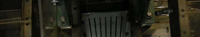
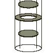
15 Mixer-Settler


16 Mixer-Settler Attributes Discrete stage units (with efficiencies < 1) Low capital cost Offer a wide range of capacities and simple operation Limited instrumentation required Requires large amount of floor space (but low headroom) Large solvent inventory Long residence times for processes with slow kinetics - results in increased solvent degradation Geometrically safe design has limited capacity
17 Mixer-Settler Control Requirements Mixer speed Interface in settling chamber is controlled by overflow weir for the light phase and underflow weir for heavy phase Weir system may be adjustable on lab scale units but typically fixed in production equipment


18 Quinn Mixer-Settlers at INL 1.5 LPM Capacity
19 Columns Unlike mixer-settlers, columns are contactors without t individual id extraction ti stages. Continuous contactors - a column is equivalent in work terms to several theoretical countercurrent stages. Columns have been used extensively at Hanford, the INL, and in the UK, France, and Japan, primarily for the PUREX process. Typical columns are feet high and provide 5-7 stages of separation per column, dependant d upon flowsheet.
20 Columns Two types of columns employed industrially Packed columns Filled with packing material, such as Raschig Rings, to create a tortuous path for the two solutions as they flow through the column ensuring that the two phases are in constant contact. Not very efficient Large height required to achieve one theoretical stage Pulse columns Trays or perforated plates are used for mixing and mechanical energy (pulsing) provided Increased efficiency and reduced height of theoretical stage First patent on pulse column in 1930 s
21 Pulse Columns Operation Solvent (light phase) circulating from the bottom to top of the column, with an aqueous (heavy) phase flowing countercurrent. The aqueous phase, which disperses in droplets (organic continuous mode), is immiscible with the solvent. Liquids are moved back and forth with a pulser to create turbulence as they encounter trays. Can also operate by dispersing the organic phase in the aqueous phase (aqueous continuous mode). Phases separate in disengaging heads Pulse frequency and amplitude are adjustable to achieve desired mixing.
22 Pulse Column Attributes Several feet of column needed for one theoretical stage Low capital cost No moving parts required in cell Requires large amount of head space (40-50 ), but little floor space Moderate solvent inventory Variable residence times


23 Pulse Columns Pulse column at La Hague UP3 and Marcoule
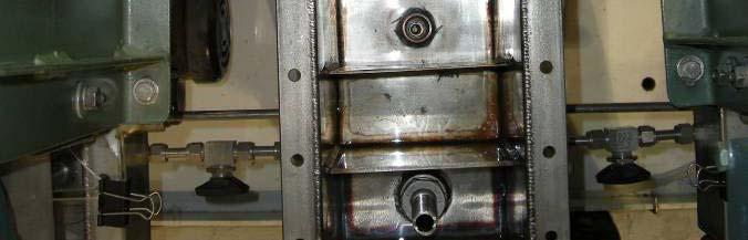
24 Pulse Column Capacity


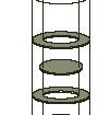

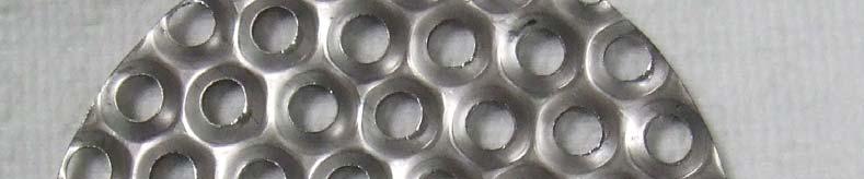
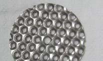
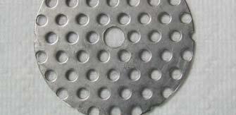
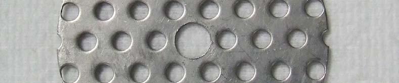

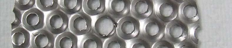


25 Pulse Column Types Disk and Doughnut Nozzle Plate Sieve Plate
26 Pulser types Mechanical Pulsers Mechanical devices, such as pistons, that move back and forth to displace the solution in the column Produce a sinusoidal wave form Issues with complexity, leakage past seals, and space requirements Fluid-Operated d Pulsers Use non-compressible fluids with camoperated bellows or incompressible fluid (air) connected to the column with a u- tube. All mechanical parts can be located remotely Several types of air pulsing devices are available: solenoid valves on pressure and vent lines, cam or air-actuated poppet valves, and rotary disk pulser
27 Pulse Column Control requirements Pulse frequency Pulse amplitude Interface I t f control Bubble probes installed in disengaging section that contains the interface Fixed space between probes and pressure differential is measured to determine interface location Interface location controls airlift which transfers heavy phase solution from column
28 Centrifugal Contactors Provide mixing and separating in single compact unit Centrifugal contactors successfully developed and operated at Savannah River Site since mid 1960 s Annular design developed in late 1960 s by ANL Centrifugal contactors are routinely used in the U.S., France, Russia, China, and Japan to develop solvent extraction flowsheets for advanced nuclear fuel cycles and radioactive waste treatment. Currently being used in France in a Pu purification cycle at La Hague Will be used by SRS in CSSX process (12.5-cm and 25-cm diameter)


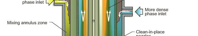


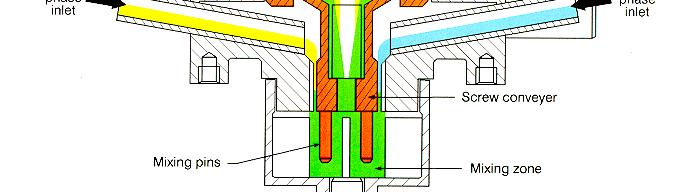
29 Schematic of Annular Centrifugal Contactor


30 Schematic of Russian (non-annular) ( ) Centrifugal Contactor


31 Centrifugal Contactor Attributes Discrete stage units (with efficiencies approaching 100%) Offer a wide range of capacities and simple operation Quick to reach steady-state Requires small amount of floor space and low headroom Small solvent inventory Short residence times resulting in reduced solvent degradation Remotely operable/maintainable Solids handling is an issue Requires motor in-cell Contactor fitted with polymer housing
32 Centrifugal Contactor Throughput/ Residence Time Units sized to meet process flow requirements 5 to 60 mlpm, 2-cm rotor (ANL) Laboratory scale 0.1 to 2 LPM, 5-cm rotor, (V02) Engineering scale 1 to 20 LPM, 12.5-cm rotor, (V05) Production scale 20 to 100 LPM, 25-cm rotor, (V10) Production scale 75 to 300 LPM, 40-cm rotor, (V16) 500 Production scale 200 to 700 LPM, 50-cm rotor, (V20) Production scale 100 t (LPM) Throughput Rotor Diameter (cm) Residence Time (s) Rotor Diameter (cm)


33 Clean-in-Place Capability Method to remove accumulated solids from rotor interior Use liquid (water or chemicals) at approximately 40 psig to spray interior of rotor through nozzles on center shaft Solutions drain through bottom of centrifugal contactor
34 Centrifugal Contactors Control Requirements Rotor Speed controlled with variable speed motor drive Weir setting often adjustable with lab and pilot scale centrifugal contactors but fixed for production equipment Heat exchanger jackets can be included on centrifugal contactor stages to control temperature in sections of the flowsheet. Temperature control of feed solutions likely adequate for many applications
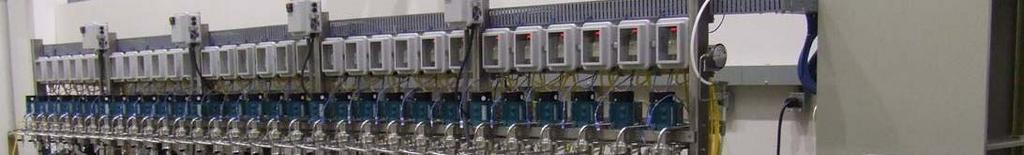
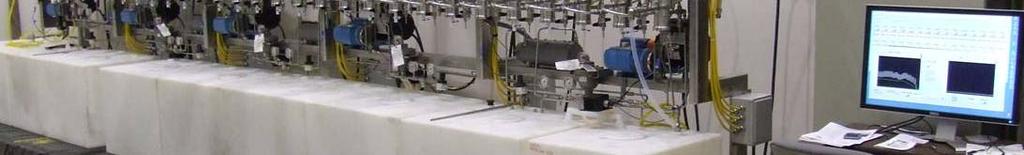
35 5-cm Centrifugal Contactor Pilot Plant at INL


36
37 Summary Mixer-settlers, pulse columns, and centrifugal contactors have been successfully used in the nuclear industry for decades Improvement in equipment design has allowed for more reliable and efficient operation The equipment types each have advantages and disadvantages To determine the appropriate equipment to use for a specific application, the following must be evaluated: criticality constraints, process (holdup) volume, process complexity (operability), reliability, maintenance philosophy, throughput, costs and performance issues such as solvent exposure (contact time), solids tolerance, flow rate turndown, equilibrium upset resistance, and process kinetics.