Cryogenic Expanders Operating on LNG-FPSO Vessels Hans E. Kimmel
|
|
|
- Duane Atkins
- 5 years ago
- Views:
Transcription
1 Cryogenic Expanders Operating on LNG-FPSO Vessels Hans E. Kimmel Executive Director Research and Development Ebara International Corporation Sparks, Nevada, USA

2 Hans E. Kimmel is Executive Director for Research and Development at Ebara International Corporation. He holds a Master Degree in Mechanical and Process Engineering and a PhD from Munich, Germany. His main contributions are primarily in the LNG technology.

3 Ebara Headquarter and Factory, Nevada, USA
4 EBARA International Corporation Cryodynamics Division Company Profile Established in 1973 Manufacturer of custom engineered liquefied gas pumps and expanders Located in Sparks, Nevada, USA Division of Ebara Corporation of Japan 5000 M2 factory with a modern, dedicated liquefied gas test facility ISO 9001 Certified

5 Ebara LNG Test Facility in Nevada, USA
6 The liquefaction of Natural Gas requires a significant amount of energy for the refrigeration process
7 Replacing the Joule-Thomson Valves with Cryogenic LNG Expanders reduce this amount of energy

8 Large 2.6 MW Cryogenic LNG Expander for Algeria, Skikda, at the Ebara Test Stand in Sparks, Nevada, USA
9 Pressure reduction across the J-T valve produces 10% undesirable vapour and only 90% of the liquid LNG is delivered to the storage tank


10 Liquefaction Process without LNG Expander in Existing Plants with 100% Liquefaction Capacity. Only 90% of LNG is produced.


11 Liquefaction Process with LNG Expander in Existing Plants with 100% Liquefaction Capacity. The LNG production increases from 90% to 95%
12 LNG Expander reduces the amount of undesirable LNG vapour from 10% to only 5%. In existing plants 95% of the condensed LNG is delivered to the storage tank An additional 5%,
13 Cryogenic LNG Expanders have been in operation for more than 16 years LNG Expanders remove energy from the LNG stream by converting the pressure into electrical energy decreasing the total power consumption
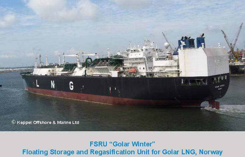
14 Floating vessels in recent years have almost the entire LNG technology chain, originally developed and utilized on-shore, applied for the exploration and exploitation of abundant off-shore natural gas wells.
15 FSRU Floating Storage Regasification Units, FPSO Floating Production, Storage & Offloading Units, FDPSO Floating Drilling, Production, Storage & Offloading Units are floating vessels used by the offshore industry for the drilling, processing, storage and transportation of LNG and for offloading the cargo in gaseous form at the destination.
16
17 Cryogenic LNG Expanders are part of every new land based liquefaction plant since 1996, and they are also part of the new off-shore LNG technology with its diverse floating units.
18 LNG Expanders are to be applied and utilized in the floating production, storage, offloading, regasification and reliquefaction of LNG, to increase the economical benefits of the entire system.
19 Ship movement is one of the most critical conditions for rotating equipment installed on floating units, particularly affecting the seating and the bearings
20 Rotating equipment with a vertical rotating shaft, like LNG pumps and expanders, is designed with a centre of gravity as low as possible to reduce the mechanical momentum generated by the ship movement.

21 Cross section of a land based LNG Expander. The LNG stream enters at the top and flows downward across the expander. The heavy generator mounted above the hydraulics puts the centre of gravity at a higher level.

22 Cross section of a floating LNG Expander. The LNG stream enters at the bottom and flows upward across the expander. The heavy generator is mounted below the hydraulics. The centre of gravity is at a lower level.
23 The ship movement, pitching and rolling, inflicts continuous side forces on the expander that can damage the rotating shaft and introduce stress to the shaft bearings. A specially designed seating and locking device is installed to secure the expander from this possible damage.
24 During off -shore operation, the expander rotor experiences gyroscopic forces. Acting on the rotating shaft bearings in radial direction, these gyroscopic forces are relatively small and depend on the rotating mass and speed.
25 Cryogenic expanders on floating units are used for refrigeration in the LNG liquefaction process and also for power recovery in the LNG regasification process.
26 Power Recovery LNG regasification plants are large heat sinks and require large heat sources. The difference in temperature between the heat source and the heat sink are in the range of 170 Celsius, providing the preconditions for efficient power recovery.
27 Power Recovery Cycle with Two-Phase Expansion
28 Net Generated Power = h NP h NP = (h 3 h 4 ) (h 2 h 1 ) Expander Power Pump Power
29 Schematic of the Two-Phase Power Cycle


30 Compact Assembly of a pump and a two-phase expander The working fluid LPG is passed through two separate heat exchangers and a single machine which combines a pump and a two-phase expander
31 Advantages of the Compact Assembly The expander work output is larger than the pump work input and the difference in work is converted by the generator into electrical energy The losses of a separate pump motor are eliminated The losses of the induction generator are recovered and used to heat the working fluid in addition to the heat from sea water and other heat sources
32 Advantages continued Any leakage of the working fluid is within a closed loop and occurs only between pump and expander Any leakage of the working fluid is minimized due to equal pressure on both sides of the seal, and small leakages are within a closed loop and occur only between pump, expander and generator. The axial thrust is minimized due to opposing directions of the thrust forces, decreasing bearing friction and increasing bearing life.

33 Existing Field Proven Two-Phase Expanders Cross section of a Two-Phase LNG Expander inside pressurized containment vessel with lower inlet and upper outlet nozzle

34 Metallic: Two-Phase Draft Tube Green: Jet Exducer Yellow: Turbine Runner Red: Nozzle Ring Two-Phase hydraulic assembly

35 Two-Phase LNG Expander at the Ebara Test Stand in Nevada, USA


36 Thank You for Your Attention