Polymer Electrolyte Fuel Cell RESEARCH at NEWCASTLE
|
|
|
- Monica Williams
- 5 years ago
- Views:
Transcription
1 Polymer Electrolyte Fuel Cell RESEARCH at NEWCASTLE Professor Keith Scott School of Chemical Engineering and Advanced Materials
2 CONTENT Polymer Electrolyte Membrane Fuel Cells (PEMFC) ISSUES Intermediate Temperature PEMFC Direct Alcohol and other PEMFC
3 Fuel Cell RESEARCH at NEWCASTLE in THE ELECTROCHEMICAL AND MATERIALS PROCESSING CENTRE EPSRC SUPERGEN FUEL CELL CONSORTIUM: Imperial College, St Andrews and Nottingham Universities, Rolls Royce, Johnson Matthey and Ceres Power A European Training Site: ELECTROCHEMICAL ENERGY AND ENVIRONMENTAL SYSTEMS
4 NEWCASTLE PEM FUEL CELL PROGRAMMES Intermediate temperature Polymer Electrolyte Fuel Cell Capillary Fuel cells Direct Methanol and Ethanol fuel cells Mixed Reactant Fuel Cell Non Pt oxygen reduction catalysts DMFC stack with new anodes Methanol tolerant catalysts Intermediate temperature proton conducting membranes Sodium borohydride fuel cells Fuel cells for portable applications Alkaline conducting membranes in fuel cells Direct propane and DME fuel cell Two-dimensional modelling of hydrogen and direct methanol fuel cell Modelling of new anodes for the DMFC. Microbial fuel cell Enzyme fuel cells
5 POLYMER ELECTROLYTE {PROTON EXCHANGE} FUEL CELL FUEL (H 2, CH 3 OH) O 2 /Air H 2 = 2 H + + 2e - H + catalyst and gas diffusion layer catalyst and gas diffusion layer Cathode reaction: 1/2O H + + 2e - H 2 O Membrane ( µm)


6 WHY PEMFC High Efficiency when operated at high cell voltage No toxic emissions Fast response High Power Density (when operated with pure reactants) Current densities > 2A/cm 2 achieved Up to 1 W/cm 2 achieved by: Optimised high surface area catalyst utilisation. Thin highly conducting electrolyte.
7 Typical PEMFC Voltage characteristics

8 CURRENT PEMFC Based on Nafion or other similar materials They need water Temperature of operation 80 o C Low temperatures mean: - relatively low rate of ORR - low value of waste heat - low anode reaction rates with other fuels Water balances and thermal balances difficult - Heat transfer rate in cells is low Fuel cell favours pure H 2 as fuel - Electrode tolerates CO only in small concentrations CO Poisoning of PEMFC Nafion membrane with Pt/C 80 o C.
9 The Way Forward -Higher Temperatures > C Advantages: Improved CO tolerance- reduce fuel processing requirements Accelerated reaction kinetics- higher performance Easier water management- simplify system design Recovery of waste heat- higher overall energy efficiency Easier heat rejection- greater driving force for heat transfer Disadvantages: Dehydration of membrane- greater ionic resistance Dry out of catalyst layer- increased polarisation
10 Two HTPEMFC Development Themes Transportation o C - Simpler stack cooling and heat usable in reforming system or in hydrogen desorption from hydrides. Membranes are likely to be based on water to provide/support ionic conductivity Combined Heat and Power > 160 o C Membranes will not require water for ionic conductivity
11 Membrane Types Hydrocarbon based, aromatics, etc.- e.g. polyether ketones, sulphones Organic-Inorganic hybrids Polymers and oxyacids; polyoxometalates (POMs); phosphomolybdic acid etc Inorganic proton conductors; e.g. metal pyrophosphates (SnP2O7 and In doped)
12 PBI High Temperature Membrane Polybenzimidazole was synthesized from 3,3 -diaminobenzidine tetrahydrochloride and isophthalic acid by a polycondensation process in polyphosphoric acid Iwakura et al. (1964) H H H H 4HCl 2H 2 O o C In PPA
13 Membrane Conductivity Q. Li et al. Danish Tech Univ Conductivity, S/cm PBI-5.6 mol H 3 PO 4 Nafion C PBI, 200 C PBI, 140 C PBI, 80 C Relative humidity, %
14 ELECTRODE PREPARATION Carbon paper SPRAYING Carbon paper + micro-porous layer SOLUTION ELECTRODES Solvent to prepare catalyst ink N,N -dimethylacetamide (DMAC) Polymer remains in a soluble state SPRAYING Carbon paper + micro-porous layer + CATALYST LAYER COLLOIDAL ELECTRODES Solvent to prepare catalyst ink Acetone Polymer precipitates Ultrasonic treatment colloid-like solid

15 SEM MICROGRAPHS COLLOIDAL ELECTRODES Formation of some small visible agglomerates (catalyst/polymer) Irregular and open structure SOLUTION ELECTRODES Uniform structure absence of agglomerates Dense surface
16 cumulative pore volume (cc/g) PORE SIZE DISTRIBUTION MERCURY POROSIMETRY "colloidal electrode" pore size (µm) "solution electrode" Enlargement of the secondary pore volume FORMATION OF THE AGGLOMERATES SEM results are fully confirmed by Hgporosimetry colloidal electrode more open structure J. Lobato, M.A. Rodrigo, J.J. Linares, P. Cañizares & K. Scott J Appl Electrochem 2006
17 FUEL CELL TESTS Voltage (mv) Current density (ma/cm 2 ) Power output (mw/cm 2 ) "solution electrode" "colloidal electrode" 125 ºC Performance of colloidal electrode > solution electrode J. Lobato, M.A. Rodrigo, J.J. Linares, P. Cañizares & K. Scott J Appl Electrochem 2006
18 High Temp. PEMFC Effect of Temperature and Pressure PBI membrane Catalyst: 0.5/0.5 mg/cm 2 anode/cathode 20% Pt on Vulcan, PBI 0.7 mg/cm 2. GDL: TGP090/20%wet -proof MPL: 1 mg/cm 2 (Ketjen black) 40% wt/wt PTFE Effect of Pressure Voltage E (mv) C 175 C 150 C Voltage E (m V) bar 1 bar Power P (mw/cm 2 ) Current density I (ma/cm 2 ) Current density I ( ma/cm -2 ) Data 2000 Membrane: 4.5% moles H3PO4 per repeat unit PBI Oxygen/Hydrogen: λ = C
19 CO Tolerance Current density, ma/cm² at 0.5V CO H 2 /O 2 (200 o C) 125 o C 0% % % % 660
20 Issues with Hydrogen Hydrogen occurs almost exclusively in combination with other elements and is not immediately accessible as fuel. Hydrogen buoyancy and flammability- accounted for in its safe use and storage Hydrogen production is currently mainly from nonrenewable fossil fuels Hydrogen s energy storage at technical levels is lower than liquid fuels Hydrogen is permeable through many materials-can result in material embrittlement Greenhouse gas Alternative Fuels such as alcohols are required


21 Direct Alcohol Fuel Cells- DAFC use C1/C2 organics
22 Experimental Fuel Cell and MEA Steel Backing Plate Assembled Cathode Anode Flow Field MEA Heating Pad PTFE Insulating Plate Silicon Gasket
23 Low temperature DAFC Performance Cell Voltage / mv Current Density / A cm -2 METHANOL T=50C MEHANOL T=60C METHANOL T=70C ETHANOL T=50C ETHANOL T=60C ETHANOL T=70C Cell temp: 50 C, 60 C,70 C, with air fed cathode 1.0 bar abs.; 1M methanol and ethanol concentration; PtRu/C as anode catalyst 1mg/cm 2 ;Pt/C as cathode catalyst 1mg/cm 2
24 Power Densities are Reasonable Power Density (mwcm-2) Current Density (macm -2 ) Methanol P=1 BAR ( ABS.) Ethanol P=1BAR ( ABS.) Methanol P=2BAR(ABS.) Ethanol P=2 BAR (ABS.)
25 Methods to Improve DAFC Performance STOP CROSSOVER- NEW MEMBRANES ETHANOL TOLERANT CATHODES HIGH TEMPERATURE IMPROVE ANODE CATALYST and UTILISATION.
26 Direct Methanol Alkaline Fuel Cell e - CH 3 OH OH - O 2 CO 2 Pt catalyst and gas diffusion layer Anode reaction: CH 3 OH + 6OH - CO 2 +5H 2 O + 6e - Pt catalyst and gas diffusion layer Cathode reaction: 3/2O 2 + 3H 2 O + 6e - 6OH - Anion exchange membrane
27 Alkaline Membrane DMFC Power density, P/mW.cm C 40 C 50 C 60 C Oxygen air Potential, E / mv n curves and 30 C 50 C 40 C 60 C Power density, P / mw.cm Temperature Current density, j / ma.cm -2

28 Flexible Fuel Cells PtRu/Ti electrode Aim to produce a portable fuel cell design that offers flexibility in application, and can use several liquid based fuels. Optimisation of electrocatalysts Examination of oxidation of organic fuels e.g. ethanol, formic acid, isopropanol, dimethyl ether, ethylene glycol, etc To operate at o C with air at near atmospheric pressure. The portable fuel cell will produce 5 W power (1.2 to 2 V) using 4-6 cells.
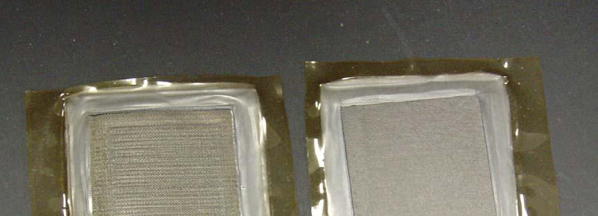

29 MEA constructions a. Mesh based and b. regular a b
30 Comparison of Methanol Oxidation in 2M MeOH a. Conventional, b. Thermally Decomposed and c. Electrodeposited Pt-Ru catalysts Anode Voltage / mv RHE b c a Current Density / ma cm -2
31 METHANOL TOLERANT CATHODES TETRAMETHOXYPHENYLPORPHYRIN FeTMPP-Cl and CoTMPP-Cl Platinum based Binary catalysts Pt-Co, Pt-Cr, Pt-FeO x Ruthenium based binary and ternary catalysts Ru-Se-Mo, Ru -Se, Ru-S-Mo Rhodium based catalysts
32 DMFC Performance with Ru-Se Standard Configuration Effect of methanol concentration 1 M, cell voltage. & 1 M, power density ) 2 M, cell voltage. ( 2 M, power density. ) 4 M, cell voltage.! 4 M, power density. Cathode: RuSe/C HTT Peak Power of >30mWcm -2 at 2 bar O 2.(4 M Methanol) >40 mwcm -2 Better than Pt with 10 M methanol Cell voltage/v Current density/ma cm Power density/mw cm -2
33 MIXED REACTANT FUEL CELL CH 3 OH CO 2 Pt/Ru catalyst O 2 H + H 2 O Non Pt catalyst CH 3 OH/O 2 /N 2 H 2 O
34 Mixed Reactant Fuel Cell Performance Cell voltage / mv (a) (b) (c) (d) (e) (f) (g) (h) Power density / mwcm Current density / macm -2 Polarisation data at 90 o C for (a) Fe-CoTMPP (b) FeTMMP, Co-TMPP (d) Ru-Se. The corresponding power density data shown in (e), (f), (g), and (h)
35 Conclusions Intermediate Temperature Fuel Cells PBI-Phosphoric acid doping!- leaching can be controlled Slow oxygen reduction catalysis in presence of phosphate Lower power densities than with low temperature PEMFC Higher Pt catalyst loadings New membranes emerging Direct Alcohol Fuel Cells Lower power densities Fuel crossover High catalyst loadings Alternative fuels and cells emerging

 Fabrication of tubular")

36 Achievements Include First UK DMFC 0.5 kw Stack in 1999 First to demonstrate alkaline membrane in DMFC Titanium mini-mesh supports for anode (and cathode catalysts) Fabrication of tubular capillary MEA DMFC with methanol tolerant nonplatinum catalysts First to demonstrate mixed reactant DMFC 50 W DMFC with mesh based flow fields
37 Acknowledgements EU through FP6 funding of FURIM UK Research Council- EPSRC EPSRC SUPERGEN Fuel Cell Consortium Newcastle Research Group- NRG