ORGANIC RANKINE CYCLE TECHNOLOGY PRODUCTS AND APPLICATIONS APRIL 2013 EAR 99 - NLR
|
|
|
- Erick Payne
- 5 years ago
- Views:
Transcription
1 ORGANIC RANKINE CYCLE TECHNOLOGY PRODUCTS AND APPLICATIONS APRIL 2013


2 UNITED TECHNOLOGIES CORP. Hamilton Sundstrand Pratt & Whitney Sikorsky Otis UTC Fire & Security UTC Power Carrier 2
 Industry Leader Leading provider of ORC s 400 kw to")


")
3 TURBODEN OVERVIEW PWPS acquired a majority stake in Turboden in 2009 Turboden Organic Rankine Cycle (ORC) Industry Leader Leading provider of ORC s 400 kw to 10 MW Customized for >10 MW 249 plants in 27countries Biomass Geothermal Heat recovery Solar thermal 2012E sales % of segment: 67% Simple and efficient generation of electric power and heat from biomass 213 plants, 228 MW 2012E sales % of segment: 26% Electricity production from medium-to-low temperatures (90 C to 180 C) 7 plants, 20 MW 2012E sales % of segment: 7% Electricity production from sources such as industrial waste heat and reciprocating engine sources 25 plants, 41 MW Conversion of heat harnessed by solar collectors into electricity through an efficient thermodynamic cycle First plant (6 MW) currently under construction in Hawaii 3
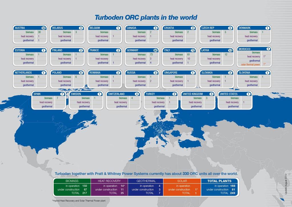
4 GLOBAL INSTALLATIONS 4
5 HEAT TO ELECTRICITY GENERATION Cooling Air conditioner Electricity Combustion Fuel Emissions Cost Fuel Cost Heat PureCycle Power System Electricity 5
6 THE ORC TECHNOLOGY The turbogenerator uses the hot temperature thermal oil to pre-heat and vaporize a suitable organic working fluid in the evaporator (8 3 4). The organic fluid vapor powers the turbine (4 5), which is directly coupled to the electric generator through an elastic coupling. The exhaust vapor flows through the regenerator (5 9) where it heats the organic liquid (2 8). The vapor is then condensed in the condenser (cooled by the water flow) (9 6 1). The organic fluid liquid is finally pumped (1 2) to the regenerator and then to the evaporator, thus completing the sequence of operations in the closed-loop circuit. 6
7 EFFICIENCY VS TEMPERATURE EFFICIENCY APPLICATION HEAT CARRIER HEAT RELEASE 25-27% Biomass / Heat Recovery / CSP Thermal Oil 310 C Water 25 C 19% Biomass (CHP) Thermal Oil 310 C Water 80 C 19% Heat Recovery Thermal Oil 275 C Water 25 C 16% Geothermal / Heat Recovery Water 180 C Water 30 C 10% Geothermal Water 100 C Water 10 C 7.5% Geothermal / Heat Recovery Water 90 C Air 15 C 7
 ORC heat output (hot water) 1 MWe modular ORC")
8 MAIN COMPONENTS Condenser- Recuperator Electric generator Electric cubicles ORC turbine Preheater Evaporator Feed Pump ORC heat input (thermal oil) ORC heat output (hot water) 1 MWe modular ORC unit 8
9 HEAT RECOVERY APPLICATIONS 9
 Thermal oil circuit Exhaust Heat recovery exchanger gas/thermal oil gas Filters /")
10 IC ENGINES: UP TO 10 % ADD L PWR ELECTRIC POWER ORC TURBODEN Cooling water circuit Heat dissipation system (dry or wet) Thermal oil circuit Exhaust Heat recovery exchanger gas/thermal oil gas Filters / Chimney 10

 Thermal oil / Steam /")

11 GAS TURBINES: 25-30% ADD L PWR ELECTRIC POWER Cooling circuit Heat dissipation system (dry or wet) Thermal oil / Steam / Pressurised water circuits Heat recovery exchanger Silencer/ Exhaust Gas Turbine 11


12 GAS TURBINES TYPICAL OUTPUTS SGT-700 Siemens SGT-400 SGT-500 Siemens NOTE: Estimated values assuming ambient air temperature of 15 C, nominal load operation 12

13 HEAT RECOVERY APPLICATIONS 13
14 ORC AT A CEMENT PLANT Exhaust gas streams: Kiln pre-heater gas Clinker cooler gas Exhaust Gas: High dust content Different operating conditions depending on mill operation, season, etc 14

15 STEEL INDUSTRY Rolling, forging Heat treatment Strip processing Sinter Blast furnace BOF EAF Relatively clean exhaust gas at moderate temperature Cost effective for ORC ~ 1 MW Interface between process and energy recovery unit is critical Exhaust gas: high flow high temperature high dust content large variations in operating cycle environmental constraints


16 ELECTRIC ARC FURNACE 25% - 30% of the power input to the furnace is lost in the exhaust C C C 70% of the lost power recoverable ORC Target: 3-5% of the EAF consumed power 16
17 BIOMASS FUELS & APPS. Biomass fuels Applications Standard Units Wood biomass: sawdust, woodchips, bark, treated wood Other biomass: dried sewage sludge, straw, green cuttings, rice husk Waste material Waste recycling wood Timber drying in sawmills Saw dust drying in wood pellet factories Air pre-heating in MDF industry District Heating networks Refrigeration / air conditioning CHP or HRS Cogeneration and/or trigeneration Up to 25% efficiency 17
18 HIGH OVERALL EFFICIENCIES 100 % Thermal power from thermal oil 73% to 78% Thermal power to heat users 20% to 25 % Gross electric power 2 % Thermal losses (insulation and generator losses) 18
19 TYPICAL SAWMILL APPLICATION ELECTRIC POWER BIOMASS POWERED BOILER bark sawdust Thermal oil ORC TRUNKS SELECTION BARKING PROCESSING Cold water Hot water PRODUCT PACKAGING DRYING 19

20 GEOTHERMAL APPLICATION 20


21 ORC DESIGN CONSIDERATIONS Key issues: Corrosion need special (costly) materials for heat exchangers Scaling leads to limits in cooling the geothermal brine Fouling - need removable covers / straight cleanable tubes Working fluid flammability: critical in urban areas & for insurance cost Vapour plume and need for makeup water in case of evaporative cooling systems Larger footprint and noise emissions from the fans in case of air cooling 21


22 ORC DESIGN CONSIDERATIONS Evaluation of the proper cooling system: Wet vs Dry WATER CONDENSERS EVAPORATIVE TOWERS EVAPORATIVE CONDENSERS AVAILABLE MAKE UP WATER Evaporative towers Smaller footprint Lower noise emissions Fresh water consumption Chemical water treatment operation cost, environment Air condensers Larger footprint Higher noise emissions No water needed Virtually no environmental impact and low operating costs AIRCOOLERS AIR CONDENSERS NOT AVAILABLE Critical issues Investment costs: initial / overall Generated yearly output, linked to gross power and parasitic loads Which is best then? 22

23 SOLAR THERMAL + ORC Hot thermal oil Emission Free Electricity Cold thermal oil 23

24 1 MW SOLAR THERMAL + ORC Power output: 1 MW el Conceptual rendering of an hybrid solar thermal system based on a Turboden 12 HRS 24
25 ORC VERSUS STEAM Parameters Steam Turbine ORC Need to Superheat the Vapor Control of Steam Quality Requirement of Qualified/ Specially Trained Personnel Complex/Costly Maintenance Turbine Corrosion/Erosion Yes: Steam turbine operates at temperatures of 450C. Yes: System required to continuously monitor & control the salt & acidity content of the water. Blow down is also required. Yes: 24 hr supervision of a qualified operator is required. Yes: Expensive maintenance and major overhauls at 5 year intervals. Yes: with non-optimal steam quality and in case of condensation in turbine. No: ORC operates at much lower temperatures with saturated organic fluid vapor. No: System with organic fluid/vapor in a closed loop with pressure higher than atmospheric pressure. No: ORC is completely automated and does not typically require supervision by a certified operator. No: The costs are minimal. No major overhauls. No: Organic fluid is lubricant, non corrosive, no condensation risk in turbine. Turn-Down Capability Limited with steep efficiency drop. Yes: Excellent turn-down (10%) with very good partial load efficiency. Electric Power and electric Generator Potentially greater electric power produced compared to the ORC, depending upon the heat source temperatures Lower electric power output produced compared to the steam turbine. 25

26 ORC EFFICIENCY VERSUS LOAD 26
27 THANK YOU! David Paul Inter national Sales and Business Development Manager Pratt & Whitney Power Systems Connecticut, USA Mobile: