Theme 4. Energy Efficiency. I-Fundamentals. Nguyen Thi Anh Tuyet Hanoi University of Science and Technology
|
|
|
- Antony Cook
- 5 years ago
- Views:
Transcription
1 Theme 4 Energy Efficiency I-Fundamentals Nguyen Thi Anh Tuyet Hanoi University of Science and Technology
2 Energy types Contents - Primary energy - Secondary energy - The difference between power and energy Fundamental laws - Laws of thermodynamics - Law of conservation of mass Energy efficiency (EE) - Energy efficiency - Energy conversion efficiency

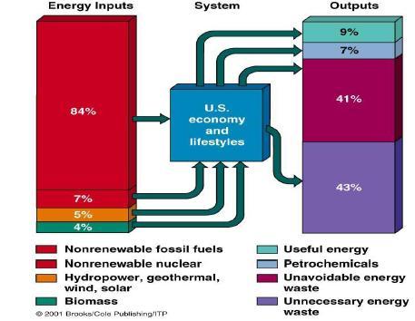
3 Primary and secondary energy
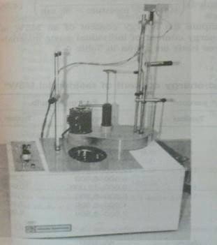
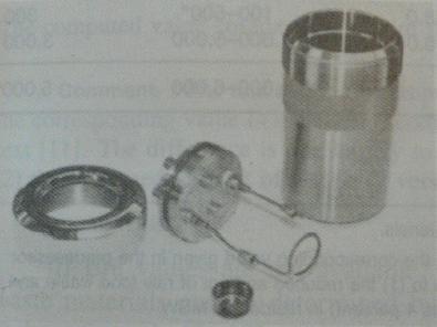
4 How to measure energy? Heating value: of a substance, usually a fuel or food is the amount of heat released during the combustion of a specified amount of it Higher heating value Gross/Higher calorific value (GCV/HCV) Lower heating value Net/Lower calorific value (NCV/LCV) NCV = GCV - water evaporating heat
5
6
7 Units of Energy Kilocalorie (or kcal) = 1000 calories Kilojoule (or kj) = 1000 joules = 0.24 kcal Joule (J) (SI): work or energy unit 1kWh = 860kcal = 3600kJ
8 The difference between power and energy - Power is the rate at which energy is transferred, used or transformed. - Power is energy divided by time
9 Laws of thermodynamics First law of thermodynamics (conservation) Energy can be changed from one form to another, but it cannot be created or destroyed. The total amount of energy and matter in the Universe remains constant, merely changing from one form to another Second law of thermodynamics (entropy) In all energy exchanges, if no energy enters or leaves the system, the potential energy of the state will always be less than that of the initial state Energy conversions are not 100% efficient This law is used to calculate the energy efficiency
10 Law of conservation of mass The mass of an isolated system (closed to all matter and energy) will remain constant over time. Mass cannot be created or destroyed, although it may be rearranged in space and changed into different types of particles. This law is used in energy and mass equivalent calculation
11 Energy efficiency (EE) Energy efficiency - (Economical) Energy used per unit of GDP of value added - (Building) Energy used per floor area - (Transportation) Energy used per a unit of distance, per capita, per weight - (Production) Energy used per a unit of production Energy conversion efficiency Energy efficiency Exergy efficiency
12 What is energy conversion efficiency? Conversion Example Chemical thermal Electrical me chanical Thermal mec hanical Boiler Electric Motor Steam turbine Effective energy use: less energy to do the same function Example: Use compact Fluorescent lamp instead of traditional lamp (use only 1/5 energy to do same function of lighting the room)

13 What is energy conversion efficiency? Less energy, less CO2 emission CO2 emission: 100g/hr CO2 emission: 20g/hr
14 Energy conversion efficiency Water boiling heat Water evaporating heat Turbine rotating work Electricity generating by turbine Electricity generating by generator The greater numbers of conversion steps, the lower of EE Lamp lighting electrical energy
15
16 Conversion efficiency Definition (How much work converted from heat) Limitation (Maximum conversion ratio) (IMPORTANT) Maximum conversion ratio is given by a function of absolute temperatures.
17 Problem: Maximum efficiency Assuming a coal power plant Vapor temperature: 900K Ambient temperature: 300K How about the case of nuclear power plant Vapor temperature: 600K Ambient temperature: 300K
18 Solution: Maximum efficiency For coal power plant ɳ - 1 = 1-300/900 = 0.66 (in real: ɳ = 42% - 50% for IGCC) Vapor temperature: 900K Ambient temperature: 300K For nuclear power plant ɳ - 1 = 1-300/600 = 0.5 (In real: ɳ ~ 35%)
19 Empirical Law The heat can naturally transfer only from the medium with higher temperature to that with lower temperature. It is impossible to convert all the heat taken from a body of uniform temperature into work without causing other changes (Kelvin s principle).
20 Definition of Exergy The exergy (W) of a system is the maximum useful work possible during a process that brings the system into equilibrium with a heat reservoir. Exergy of heat available at a temperature

21 Energy and Exergy Efficiency Efficiency: Ratio of Energy (Exergy) output by Energy (Exergy) input

22 Energy flow for cement production

23 Exergy flow for cement production
24 Theme 4 Energy Efficiency II-Energy efficiency (Industry) Nguyen Thi Anh Tuyet Hanoi University of Science and Technology
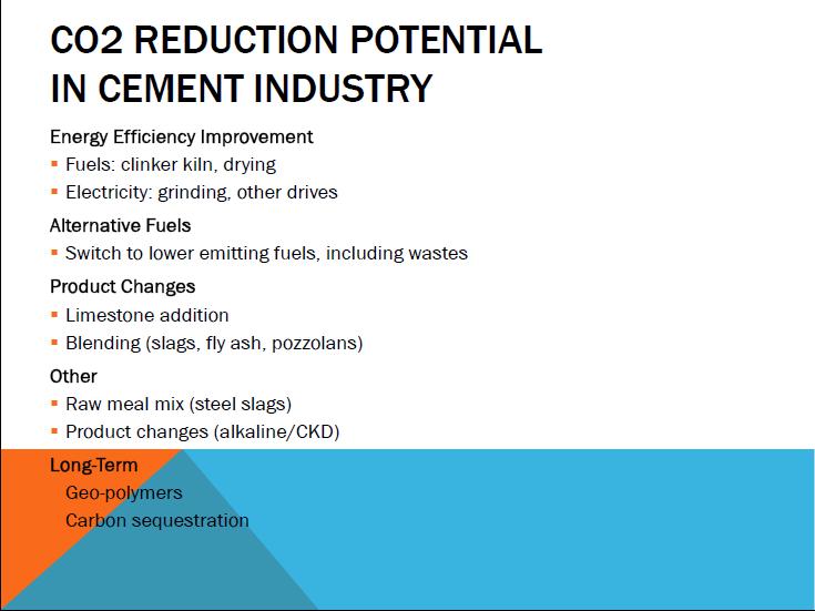
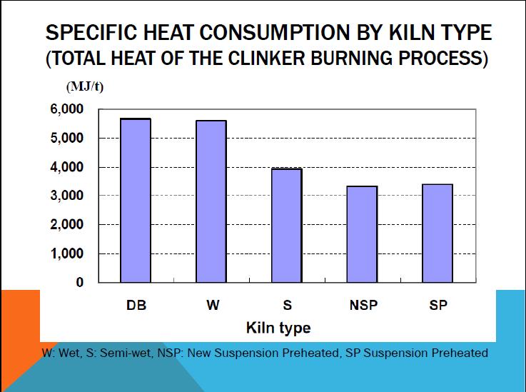
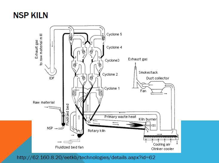
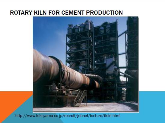
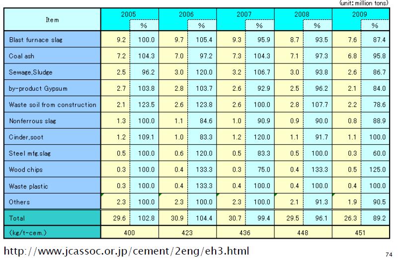
25 Contents Boiler Combustion reactions of fuels Boiler types Heat loss calculation Cement production Rotary kiln, NSP kiln Energy consumption and CO2 reduction potential Beer production Energy consumption Technologies (VRC, CCS, Opt-Past, )
26 Boiler
27
28 1. Combustion reactions of fuels Complete combustion reaction Incomplete combustion reaction H combustion S combustion
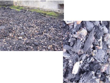
29 Combustion process (theoretical) Fuels Air (kg)/fuel (kg) CO2 % Solid fuels Bagasse Coal (bitumen) Lignite Rice husk Wood Liquids fuels Oil low sulfur oil 3,3 10,7 8,5 4,5 5,7 13,8 14, ,
30 Excess air coefficient Definition of excess air In industry, combustion excess air is supplied in addition to theoretical amount required for combustion Excess air coefficient λ = supplied amount/theoretically required amount Too high λ Causes decrease in combustion temperature and thermal efficiency Too low λ Incomplete combustion reaction, high CO amount, decrease in boiler efficiency, etc Optimal λ?
31 Optimal excess air coefficient Fuels λ [O2] % of exhausted gas Gas FO Firewood Coal Powder Chain-grate 1,1 1,2 1,3 1,25-1,30 1,35-1,40 2,2 4,0 4,5 4,3-4,9 5,5-6,0
 Milled coal Coal Oil Gas Firewood Bagasse")
32 Fuels Typical excess air coefficient of fuels Combustion chamber type Excess air (% weight) Milled coal Coal Oil Gas Firewood Bagasse bitumen
33
34 2. Boiler types Fire tube boiler Water tube boiler Package boiler Spreader stoker boiler Chain-grate or Traveling-grate Stoker boiler Pulverized Fuel Boiler Waste heat recovery boiler Fluidized bed combustion (FBC) boiler

35 Fire-tube boiler Working principle - The heat of the gases is transferred through the walls of the tubes by thermal conduction, heating the water and ultimately creating steam. Application - Small capacity (12 ton/h) - Low pressure (18kg/cm2) Fuels: -Coal, oil, gas Schematic diagram of fire-tube boiler Package design

36 Water-tube boiler Working principle - Water circulates in tubes heated externally by the fire. Fuel is burned inside the furnace creating hot gas which heats water in the steamgenerating tubes Application - Capacity: 4,5-120 ton/h - High thermal efficiency Fuels: - Oil, gas (package design ), solid Schematic diagram of water-tube boiler
 The most widely used fuels are heavy oil, light oil, and gas.")
37 Package boiler Package boilers require less fuel and electric power to operate Operates more efficiently if the oxygen concentration in the flue gas is reduced The typical package boiler is a water tube boiler or flue and smoke tube boiler with a capacity of 5 to 20 t/h (average steam generation capacity) The most widely used fuels are heavy oil, light oil, and gas. Schematic diagram of package boiler Fire-tube boiler

38 Spreader stoker boiler Working principle - Spreader stokers utilize a combination of suspension burning and grate burning. - The coal is continually fed into the furnace above a burning bed of coal. Application - This method of firing provides good flexibility to meet load fluctuations, since ignition is almost instantaneous when firing rate is increased. Schematic diagram of spreader stoker boiler - Be favored over other types of stokers in many industrial applications.

39 Chain-grate or Traveling-grate Stoker boiler Working principle Coal is fed onto one end of a moving steel grate. As grate moves along the length of the furnace, the coal burns before dropping off at the end as ash. The coal-feed hopper runs along the entire coal-feed end of the furnace. A coal gate is used to control the rate at which coal is fed into the furnace by controlling the thickness of the fuel bed. Schematic diagram of Chain-grate boiler

40 Pulverized Fuel Boiler Working principle - The coal is ground to a fine powder, blown with part of the combustion air into the boiler plant through a series of burner nozzles. - Secondary and tertiary air may also be added. Combustion takes place at temperatures from C Application - For coal power plants and industrial watertube boiler - One of the most popular systems for firing pulverized coal is the tangential firing using four burners corner to corner to create a fireball at the center of the furnace Schematic diagram of Pulverized fuel boiler
 Application Widely applied to waste heat from gas turbines or diesel engines Directly use for heat processes Common in the")
41 Waste heat recovery boiler Working principle - Generate steam by recovering the heat value in the stream. Salvage waste heat (at highmedium temperature) Application Widely applied to waste heat from gas turbines or diesel engines Directly use for heat processes Common in the process industries. Schematic diagram of Waste heat recovery boiler

42 Fluidized bed combustion (FBC) Boiler - Combustion at 840oC 950oC - High combustion efficiency and less pollutants of SOx and NOx - Fuels: Coal, rice husk, bagasse, agricultural by-products - Types: AFBC: pressurized fluidized bed combustion PFBC: pressurized fluidized bed combustion CFBC: circulating fluidized bed combustion
43 3. Boiler efficiency assessment Evaporation ratio Boiler efficiency Energy balance and heat loss -Heat loss in flue gases - Bottom blow-down calculation - Boiler waste water treatment
44 Evaporation ratio Typical evaporation ratios: Coal combustion boiler at pressure of 10 bar: 6 Oil combustion boiler at pressure of 10 bar: 13 Means: 1 tons of coal can generate 6 ton of steam 1 tons of oil can generate 13 ton of steam
45 Boiler efficiency Definition Calculation method - Direct - Indirect

46 Direct Indirect

47 Energy balance of boiler

48 Heat loss of boiler Heat loss in flue gases Heat in fuel input Heat in air Boiler Heat loss in flue steam Fuel humidity Air humidity Radiation and convection Bottom blow-down Heat in steam out put
49 Heat loss in flue gases Formula Simplify: Heat loss Gas Oil Coal Measure CO2 directly (%)
50 Problem: calculate heat loss in flue gases For a coal boiler: - Operated at excess air mode (excess O2: %) - Coal consumption: 6 tons/day - Flue gas temperature: 425oC - Flue gas composition: O2 = 12,0%; CO2 = 9,0%; CO = 13236mg/m3; NO = 20-27mg/m3, NO2 = 4-8mg/m3; SO2 = mg/m3; CxHy = ppm Calculate % heat loss in flue gases? Heat loss reduction solutions?
51 Solution Heat loss in flue gases % loss = 0,65.[( )/9] = 16.25% Heat loss reduction: - Solid particulates at the bottom (too high flue gas temperature) Treat input water Remove solid particulates - High excess O2 reduce input air - Recover waste heat - Improve thermal isolation
52 Flue gas temperature and heat loss Flue gas temperature (T) influences heat loss - T high heat loss - T low high humidity corrosion (due to the presence of SO2, SO3) - Optimal temperature: oC
53 Flue gas heat recovery Due to large amount of heat, flue gas heat can be recovered to: - Dry air before entering the combustion chamber - Heat feedwater before entering the boiler Benefits Reduce the flue gas temperature Increase the temperature of feedwater Improve efficiency and reduce fuel amount
54 Heat loss in bottom blown-down Formula Where: V: Bottom blown-down water (kg/s) Hns: specific heat of boiling water Nc: specific heat of feedwater
55
56 Bottom blown-down calculation Formula Blowndown = TDS x % feedwater volume Maximum TDS of boiler water Reduce operation and treatment cost by control the blowdown rate - Reduce consumption of treated feedwater - Reduce the maintanance time - Increase the life-span of the boiler - Reduce chemical amount
57
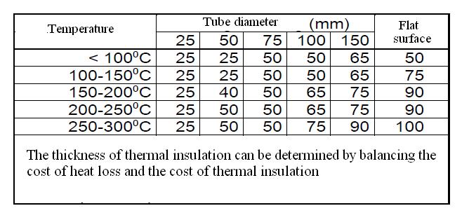
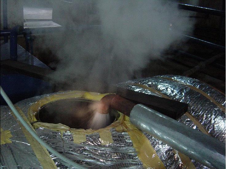
58 Heat loss from steam pipes Causes: Bad steam pipe isolation Inappropriate distance with the boiler Steam pipe leakage Formula S: Heat loss (through pipe surface), kcal/h.m2 Tbm: pipe surface temperature Tmt: surrounding temperature
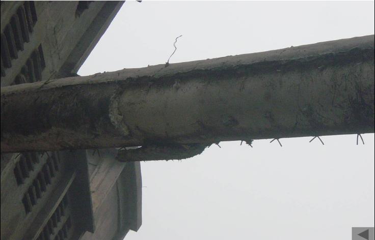
59
60
61
62
63 Cost Thickness of thermal insulation Graph determining the efficient thickness of thermal insulation
64
65
66

67
68

69
70
71
72
73
74
75 Heating and Cooling in beer Production (Effective Energy Use)
76

77

78 Gas generated with high energy Save energy by gas reuse

79 Consume less energy than the conventional system


80 Past-pasteurizer: keep bear in 60 o C in 10 minutes needs a large amount of gas After that, keep bear in 35 o C before another process Opt-past: save gas via improving efficiency

81 Hot water stream gas Thermal pump device pasteurization system when using thermal pump device
82 Consumed water volume 10 times larger than beer volume Organic waste content in Sewage is high, and it should be treated by anaerobic WWT Biogas generated is used as input fuel for boiler

83 Vapor re-compression Improving Ice Thermal Storage, Cascade Cooling Optimization of Pasteurizer Sewage purification by anaerobic disintegration process Gas from cooking system Fermentation devices

84 Thanh Hoa beer factory: 100% installed in Vietnam Energy save: toe/year KNK emission reduction: tons CO 2 /year

85 There is a limit to convert thermal energy to other form of energy. Exergy analysis is useful to evaluate the efficiency To raise the efficiency, the efficient use of thermal energy should be focused. For the future, total energy management system will be effective.
86 Thank you!