Soil Investigation for Volatile Organic Compound Soil To Groundwater Impact Site 5 - Fire Training Area. NAS JRB Willow Grove Horsham, Pennsylvania
|
|
|
- Flora Pierce
- 5 years ago
- Views:
Transcription
1

2 Soil Investigation for Volatile Organic Compound Soil To Groundwater Impact Site 5 - Fire Training Area NAS JRB Willow Grove Horsham, Pennsylvania Engineering Field Activity Northeast Naval Facilities Engineering Command Contract No. N D-0057 Contract Task Order 003 March 2006
3 PHIL SOIL INVESTIGATION FOR VOLATILE ORGANIC COMPOUND SOIL TO GROUNDWATER IMPACT for SITE 5 - FIRE TRAINING AREA NAVAL AIR STATION JOINT RESERVE BASE WILLOW GROVE, PENNSYLVANIA COMPREHENSIVE LONG-TERM ENVIRONMENTAL ACTION NAVY (CLEAN) CONTRACT Submitted to: Engineering Field Activity Northeast Environmental Branch, Code EV2 Naval Facilities Engineering Command 10 Industrial Highway, Mail Stop 82 Lester, Pennsylvania Submitted by: Tetra Tech NUS, Inc. 600 Clark Avenue, Suite 3 King of Prussia, Pennsylvania Contract No. N D-0057 Contract Task Order 003 March 2006 PREPARED UNDER DIRECTION OF: APPROVED FOR SUBMISSION BY: RUSSELL E. TURNER PROJECT MANAGER TETRA TECH NUS, INC. KING OF PRUSSIA, PENNSYLVANIA JOHN J. TREPANOWSKI, P.E. PROGRAM MANAGER TETRA TECH NUS, INC. KING OF PRUSSIA, PENNSYLVANIA
4 SECTION TABLE OF CONTENTS PAGE 1.0 INTRODUCTION SITE DESCRIPTION SCOPE OF THE INVESTIGATION SUMMARY OF FIELD INVESTIGATION BOREHOLE DRILLING SOIL SAMPLING AND ANALYSIS Lithologic Analysis Field Screening Soil Sampling and Laboratory Analysis RESULTS AND DISCUSSION COMPARISON OF CURRENT AND HISTORICAL ANALYTICAL DATA UPDATED SITE 5 CONCEPTUAL MODEL FOR SOILS SUMMARY AND CONCLUSIONS... 7 APPENDICES A B C D SURVEY DATA BORING LOGS SOIL SAMPLE LOG SHEETS ANALYTICAL RESULTS TABLES NUMBER 1 Results of Photoionization Detector (PID) Headspace Screenings 2 Data Summary of Analytical Results Soil Borings of Former Drum Storage Area 3 Data Summary of Analytical Results Soil Borings of Former Burn Ring NUMBER FIGURES 1 Location of RI Sites 2 Soil Boring Locations L/DOCUMENTS/NAVY/2192/19692 i CTO-003
5 SOIL INVESTIGATION FOR VOLATILE ORGANIC COMPOUND SOIL TO GROUNDWATER IMPACT SITE 5 - FIRE TRAINING AREA NAS JRB WILLOW GROVE HORSHAM TOWNSHIP, MONTGOMERY COUNTY, PENNSYLVANIA 1.0 INTRODUCTION Tetra Tech NUS (TtNUS) performed additional investigation of the soil at Site 5 (the former Fire Training Area) at the Naval Air Station Joint Reserve Base (NAS JRAB) Willow Grove, Pennsylvania. The work was performed under Contract Task Order No. 003 under Contract N D-0057, Comprehensive Long-Term Environmental Action Navy (CLEAN), in accordance with the approved Work Plan for Soil Investigation, Summer 2005, Volatile Organic Compound Soil to Groundwater Impact, Site 5 - Fire Training Area Soil, Operable Unit 4 (OU 4) (Tetra Tech NUS, December 2005). This work complements the previous remedial investigation work that is documented in the Remedial Investigation Report for Site 5 Fire Training Area (Tetra Tech NUS, February 2002), and the Remedial Investigation Report for Sites 1, 2, 3, and 5 (Halliburton NUS, February 1993). The purpose of this soil investigation was to address regulatory agency concerns regarding the quality of the historical analytical data for volatile organic compounds (VOCs) in Site 5 soil. Specifically, the Environmental Protection Agency (EPA) had concerns regarding the sampling methods used during the previous investigations, and requested that these locations be resampled with the EnCore TM sampling technique (a sampling method that was not available during the previous investigations) to confirm the historical results. EPA concerns included: Whether the analytical non-detections of VOCs from soil samples in the vicinity of the former burn ring could be false negatives. These samples were chosen in the field because of elevated photoionization detector (PID) responses observed during screening procedures. Whether the VOC concentrations reported for the soils containing positive detections could have been under-reported. Whether the VOC concentrations exceed the applicable benchmark screening concentrations for the soil-to-groundwater migration pathway. L/DOCUMENTS/NAVY/2192/ CTO-003
6 2.0 SITE DESCRIPTION AND SETTING NAS JRB Willow Grove is located in Horsham Township, Montgomery County, Pennsylvania, approximately 20 miles north of the city of Philadelphia. NAS JRB Willow Grove occupies 1,000 acres of the 1,200 acres maintained by the Department of Defense at the Air Station, and the Willow Grove Air Reserve Station occupies the remaining 200 acres (see Figure 1). The Air Station is generally bounded by State Route 611 (Easton Road) to the east, State Route 463 (Horsham Road) to the southwest, and Keith Valley Road to the north. Site 5 is located in the south-central portion of NAS JRB, approximately midway between Runway 10/28 and Horsham Road. The site is located immediately south of Taxiway Juliet, and covers an irregularly shaped area of approximately 1.25 acres. The training area was used from 1942 to 1975 for firefighting exercises, which included the disposal and burning of flammable liquid wastes generated by the Naval Air Station. Wastes including solvents, paint chemicals, xylenes, toluene, and various petroleum compounds were reportedly consumed at the rate of at least 4,000 gallons per year. Drums were reportedly stored in the vicinity of the burn ring during the periods between firefighting exercises. Site 5 is comprised of flat to slightly rolling terrain, and is primarily covered by grasses, buildings, and a parking lot, with some woody and brushy vegetation present within the southern portion of the area. 3.0 SCOPE OF THE INVESTIGATION The field investigation was designed to gather additional analytical data from subsurface soils at selected locations that were sampled during previous investigations. These locations included: Soil boring locations where elevated PID readings were observed in the field, but no VOCs were subsequently detected during the laboratory analyses. These soils were resampled to confirm that VOCs are not present at these locations. Soil boring locations where elevated PID readings were observed in the field, and VOCs were subsequently detected during the laboratory analyses. These soils were resampled to confirm the accuracy of the previously reported concentrations. L/DOCUMENTS/NAVY/2192/ CTO-003
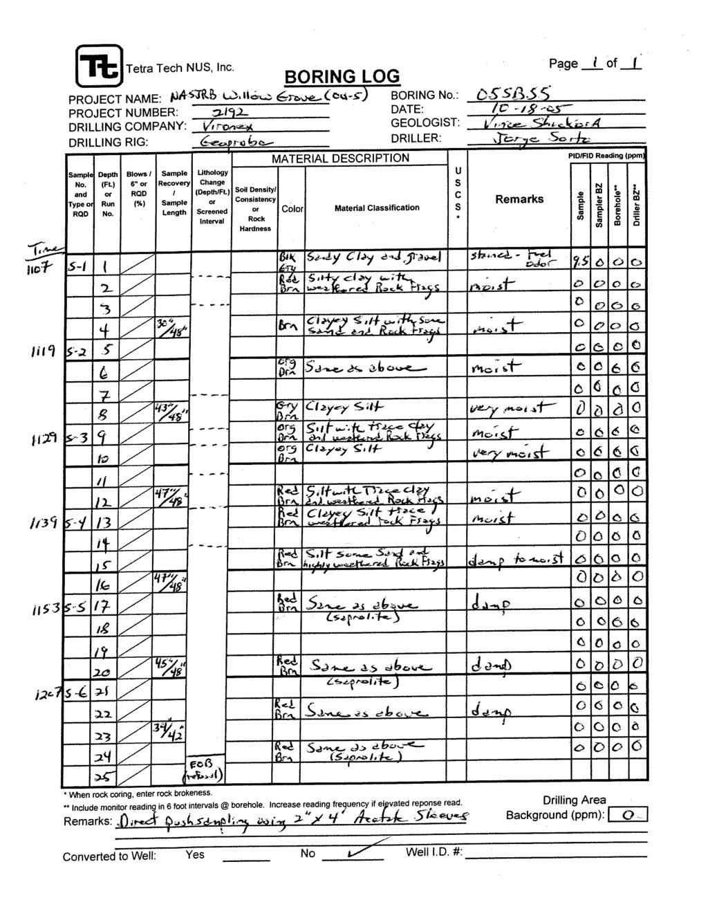
7 The following field investigation tasks were completed to address the identified data gaps: Soil Borings (see Section 4.1). Six soil borings were drilled near the locations of selected historical borings (see Figure 2). Continuous soil cores were obtained from the ground surface to the top of bedrock at each boring location. Soil Sampling and Analysis (see Section 4.2). The soil cores were screened in the field with a PID. Based on these results, two soil samples were selected from each boring using the EnCore TM sampling technique, and submitted to a fixed-base analytical laboratory for VOC analyses. 4.0 SUMMARY OF FIELD INVESTIGATION The locations of the six soil borings are illustrated on Figure 2. Three of the borings (05SB-54, -55, and -56) are located in the vicinity of the former burn ring, where no VOCs have historically been detected, and three of the borings (05SB-51, -52, and -53) are located in the vicinity of the former drum storage area, where elevated concentrations of VOCs have historically been detected. Each drilling location was cleared for subsurface utilities by NAS JRB personnel, and by contacting the Pennsylvania One-Call utility clearing system. 4.1 BOREHOLE DRILLING The drilling subcontractor was Vironex, Inc., of Bowie, Maryland. The soil borings were drilled by the direct push technology (DPT, or Geoprobe ) drilling method. With the DPT method, a sampling barrel fitted with an acetate core sleeve is hydraulically advanced (or pushed) into the subsurface to obtain a soil core. The barrel is withdrawn from the borehole, the acetate core sleeve is removed, a new core sleeve is inserted into the barrel, and the sampling assembly is reinserted into the borehole to obtain the next core. The borehole stayed open when the sampling assembly was withdrawn due to the clayey and silty nature of the soil. At each location, continuous soil samples or cores were collected from the ground surface to the top of bedrock (which was defined as hydraulic refusal, or the inability to further advance the barrel). The depths of the borings ranged from 18 to 23 feet in the vicinity of the former burn ring, and from 11 to 19 feet in the vicinity of the former drum storage area. At the conclusion of each boring, the borehole was backfilled with a mixture of soil cuttings and bentonite. L/DOCUMENTS/NAVY/2192/ CTO-003
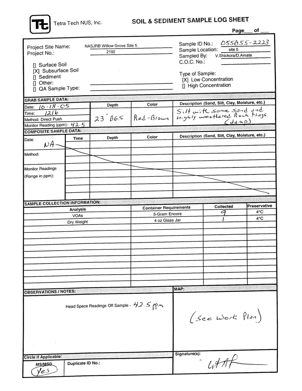
8 The soil borings were surveyed for horizontal location and vertical elevation by James M. Stewart, Inc. The survey data are presented in Appendix A. 4.2 SOIL SAMPLING AND ANALYSIS Lithologic Analysis The lithology of each core was described by the TtNUS geologist and noted on the boring log. The lithologies observed in the cores were consistent with those noted during previous site investigations, and consisted predominantly of fine-grained soils ranging from a silty clay to a sandy silt. The boring logs are included in Appendix B Field Screening Concurrent with the lithologic analysis, each core was field-screened for VOCs using a PID. These PID readings are recorded on the boring logs. In addition, headspace analyses were conducted for each core at two-foot intervals. To determine the headspace concentrations, a soil sample was placed in a clean glass jar and tightly covered with aluminum foil. The jar was then shaken to thoroughly mix the soil sample with the air in the headspace. After the sample was allowed to equilibrate for a period of 10 minutes, the foil was perforated by the PID and a headspace reading was recorded. The results of the headspace analyses are included in Table Soil Sampling and Laboratory Analysis Soil samples were collected (and preserved) every two feet from the entire borehole of each boring. Two soil samples from each boring were selected for VOC analysis by a fixed-base laboratory. One soil sample for laboratory analysis was taken from the interval displaying the highest headspace PID reading, and one soil sample was taken from the basal soils occurring immediately above the top of bedrock. No PID readings were noted at location 05SB56, so one sample was taken from the basal soils, and one sample was taken from the midpoint of the boring. All soil samples were obtained using the closed L/DOCUMENTS/NAVY/2192/ CTO-003
9 sampling vessel (EnCore TM ) sampling technique and in accordance with the sampling procedures described in Appendix B of the work plan. The samples ultimately selected for VOC analysis are shown in Table 1. The requisite QA/QC samples (including field duplicate, field blank, rinsate blank, and trip blank) were also taken and submitted as prescribed in the work plan. The sample log sheets are included in Appendix C. The laboratory analyses were performed by Northeast Laboratory Services of Waterville, Maine (a Navy-certified laboratory) using SW-846 Method 8260B. The data were validated to EPA validation level M3 by TtNUS in accordance with EPA s national and regional protocol. The complete set of validated analytical data is presented in Appendix D. 5.0 RESULTS AND DISCUSSION The analytical data obtained through the EnCore TM sampling method for this current investigation are summarized in Table 2 (for the soil borings located in the vicinity of the former drum storage area) and Table 3 (for the soil borings located in the vicinity of the former burn ring). For comparison, these tables also include the historical analytical data from the corresponding previous borings (see Figure 2 for locations) that were obtained using the now-obsolete sampling methods. 5.1 COMPARISON OF CURRENT AND HISTORICAL ANALYTICAL DATA Overall, the current analytical data compare favorably with the historical data. Although no statistical comparisons of the data sets were conducted, the level of similarity in both the qualitative (presence versus absence) and quantitative (concentration) results indicate that all existing analytical data may be confidently used for the interpretation of site conditions. Qualitatively, the list of compounds positively detected at each location in 2005 is similar to the compounds that were detected in 1997 or One exception to this trend occurred at boring location 05SB52 (2005), where 14 VOCs were detected, versus 05SB21 (1997), where 2 VOCs were detected. This difference, however, is due to the significantly higher detection limits that were reported for the 1997 sample. Quantitatively, the VOC concentrations detected in 2005 are similar to the concentrations detected in 1997 or No sampling event displays consistently higher or lower concentrations than the other L/DOCUMENTS/NAVY/2192/ CTO-003
10 sampling events, and the reported differences in concentrations are generally small. The exceedances (or non-exceedances) of benchmark criteria are consistent across the data sets. That is, the compounds that exceeded a benchmark concentration for the current sampling round typically exceeded the benchmark for the historical sampling round. Again, one exception to this trend was noted at location 05SB21, where the lower detection limits achieved for the current round resulted in the positive detection of 12 additional VOCs, and consequently a higher number of benchmark exceedances. 5.2 UPDATED SITE 5 CONCEPTUAL MODEL FOR SOILS The analytical results of the current sampling event support the existing interpretation of Site 5 soil conditions as presented in the RI report (Tetra Tech NUS, February 2002). No significant changes to this interpretation are required. The most significant VOC concentrations in the soil (based on the number of detected compounds, the VOC concentrations, and the number of benchmark screening criteria that are exceeded) are detected in the vicinity of the former drum storage area. Here, selected benchmark criteria were exceeded from subsurface depths as shallow as 1 foot (at 05SB52) to as deep as the overburden/bedrock interface (15 feet at 05SB53). In contrast, little VOC impact to the soils is detected in the vicinity of the former burn ring. In addition, the nature and extent of VOCs in the soil are very consistent with the nature and extent of VOCs in the resultant groundwater plume, where the former drum storage area (which consistently records the highest VOC concentrations for groundwater) is interpreted to be the source area of the plume. During the scoping of this project, regulators questioned the lack of historical contamination detected in the vicinity of the burn ring, and noted that the highest VOC concentrations at most fire training sites are typically detected at the burn area. However, this investigation revealed that at NAS JRB, the burn ring has a competent steel bottom, and is actually a half-buried, soil-filled tank, rather than simply a steel partition encircling unlined native soil. The tank is interpreted to have prevented the infiltration of VOCs into the underlying native soil. Soil boring 05SB55 was placed near the tank s spill point (overflow pipe) to investigate whether VOCs may have spilled out of the tank, but the analytical results indicated no VOCs in the surface soils, and very low detections of 2 VOCs at the overburden/bedrock interface (2-butanone at 2.8J ug/l and methyl acetate at 5.2J ug/l). L/DOCUMENTS/NAVY/2192/ CTO-003
11 5.3 SUMMARY AND CONCLUSIONS The purpose of this investigation was to gather additional analytical data from subsurface soils at selected locations that were sampled during previous investigations. The objective of the resampling was to address regulatory concerns regarding the quality of the historical analytical data for VOCs because of the now-outdated sampling techniques that were used. The current samples were obtained using the EnCore TM sampling method. One subset of soil samples were obtained from boring locations where elevated PID readings were previously observed in the field, but not VOCs were subsequently detected during the laboratory analyses. The results of the current investigation confirm that VOCs are not present in these areas. One subset of soil samples were obtained from boring locations where elevated PID readings were previously observed in the field, and VOCs were subsequently detected during the laboratory analyses. The results of the current investigation confirm that VOCs are present in these areas at the approximate concentrations that had been previously reported. In summary, the results of this investigation validate the historical data and indicate that all of these results may be used with confidence. L/DOCUMENTS/NAVY/2192/ CTO-003
12 APPENDIX A SURVEY DATA L/DOCUMENTS/NAVY/2192/ CTO-003
13 APPENDIX B BORING LOGS L/DOCUMENTS/NAVY/2192/ CTO-003
14 APPENDIX C SOIL SAMPLE LOG SHEETS
15 APPENDIX D ANALYTICAL RESULTS
16 TABLES
17 FIGURES
18 TABLE 1 RESULTS OF PHOTOIONIZATION DETECTOR (PID) HEADSPACE SCREENINGS NAS JRB WILLOW GROVE SITE 5 - FIRE TRAINING AREA Boring Depth Headspace Boring Depth Headspace (PID, ppm) (PID, ppm) 05SB SB54 0-1** ** ** ** SB52 0-1** SB55 0-1** ** SB ** ** SB ** ** ** 0.0 ** Interval selected for laboratory analysis. L/DOCUMENTS/NAVY/2192/ of 1 CTO-003
19 TABLE 2 DATA SUMMARY OF ANALYTICAL RESULTS VOLATILE ORGANIC COMPOUNDS (VOCs) IN SOIL NAS JRB WILLOW GROVE SITE 5 - FORMER FIRE TRAINING AREA SOIL BORINGS LOCATED IN THE VICINITY OF THE FORMER DRUM STORAGE AREA Boring: Date: 05SB SB SB SB SB SB SCREENING LEVELS Depth (feet): EPA SSL PADEP 1,1,1-Trichloroethane 10U 10U 12U 12U U 1500U J ,1,2-Trichloroethane 1U 0.55J 12U 12U 1U U 10U 0.9J ,1-Dichloroethane 0.56J 4.2J 12U 11J 290J U ,1-Dichloroethene 10U 10U 12U 12U 170J 11U 1500U 9.6J 2.4J 5J ,2-Dichlorobenzene 10U 10U NA NA 10UJ 11U NA 10U 11U NA ,2-Dichloroethane 1U 1U 12U 12U 1U 1.1U 1500U 1U 1.1U 12U ,3-Dichlorobenzene 10U 10U NA NA 10UJ 11U NA 10U 11U NA Butanone 10U 10U 12U 12U 10U 11U 1500U 10U 1.7J methyl-2-pentanone 10U 0.56J 12U 12U 10U 3.8J 1500U 10U 11U 12U Acetone 2.9B 2.1B 70 12U 47J 4.7B 1500UJ 10U 6.3B 140J Benzene 28 2U 15 20J U 1500U J Bromomethane 2U 2U 12U 12U 2U 2.2U 1500U 2U 2.2U 12U cis-1,2-dichloroethene 10U 1.3J 12U (total) 12U (total) 0.61J 11U 1500U (total) (total) Carbon Disulfide 10U 10U 12U 12U 1.3J 11U 1500U 10U 11U 12U Cyclohexane 29 10U NA NA U NA J NA Ethylbenzene U J U U 11U Isopropylbenzene 10U 10U NA NA 10UJ 11U NA 5.9J 0.6J NA Methyl Acetate 10U 10U NA NA 10U 11U NA 10U 11U NA Methylcyclohexane 160J 10U NA NA U NA J NA MTBE 1U 1U NA NA 1U 1.1U NA 1U 1.1U NA Styrene 10U 10U 12U 12U 10UJ 11U 1500U 10U 11U 12U Tetrachloroethene 2U 2U 12U 12U U 1500U U 10J Toluene 1.2J 10U 12U 12U 17 11U 1500U 10U 11U Trichloroethene 1U 1U 12U 8J 6 1.1U 1500U J Xylenes (total) U U U 11U Notes: All concentrations are reported in values of ug/kg. Listed compounds have at least one positive detection in at least one sample. Target compounds with no positive detections are not listed. EPA benchmarks are the Region 3 Soil Screening Levels (SSLs) for soil-to-groundwater migration at a dilution-attenuation factor (DAF) = 20. PADEP benchmarks are the soil-to-groundwater generic values for a used, residential aquifer with TDS < Concentrations reported for borings 05SB22, 05SB51 (4-5), and 05SB52 (10-11) are the highest reported concentrations from the field & field duplicate sample pair. U = Compound was Undetected at the posted detection limit. J = The reported concentration is estimated. B = The reported detection was qualified as blanked through the data validation process. NA = Not Analyzed Bolded concentrations represent positive detections. Highlighted concentrations represent exceedances of at least one benchmark screening value. L/DOCUMENTS/NAVY/2192/ of 1 CTO-003
20 TABLE 3 DATA SUMMARY OF ANALYTICAL RESULTS VOLATILE ORGANIC COMPOUNDS (VOCs) IN SOIL NAS JRB WILLOW GROVE SITE 5 - FORMER FIRE TRAINING AREA SOIL BORINGS LOCATED IN THE VICINITY OF THE FORMER BURN RING Boring: Date: 05SB SB SB SB SB No nearby historical SCREENING LEVELS Depth (feet): borings EPA SSL PADEP 1,1,1-Trichloroethane 10UJ 10U 5U 6U 10U 10UJ 12U 10U 10U ,1,2-Trichloroethane 1UJ 1U 5U 6U 1U 1U 12U 1U 1U ,1-Dichloroethane 10UJ 10U 5U 6U 10U 10UJ 12U 0.58J 10U ,1-Dichloroethene 10UJ 10U 1B 6U 10U 10UJ 12U 10U 10U ,2-Dichlorobenzene 1J 10U NA NA 10U 10U NA 10U 10U ,2-Dichloroethane 1UJ 1U 5U 6U 1U 1UJ 12U ,3-Dichlorobenzene 0.98J 10U NA NA 10U 10U NA 10U 10U Butanone 6.9J 10U 10U 12U 10U 2.8J 12U 10U 10U methyl-2-pentanone 10UJ 10U 10U 12U 10U 10U 12U 10U 10U Acetone 29J 10U 10U 52B 10U 1B 41J 1.5B 10U Benzene 2UJ 2U 5U 1J 2U 2UJ 12U 2U 2U Bromomethane 2UJ 2U 10U 12U 2U 2UJ 12U 2U 2U cis-1,2-dichloroethene 10UJ 10U 5U (total) 6U (total) 10U 10UJ 12U (total) 10U 10U Carbon Disulfide 1.6J 10U 5U 2J 10U 10UJ 12U 10U 10U Cyclohexane 10UJ 10U NA NA 10U 10UJ NA 10U 10U Ethylbenzene 10UJ 10U 5U 6U 10U 10U 5J 10U 10U Isopropylbenzene 10UJ 10U NA NA 10U 10U NA 10U 10U Methyl Acetate 11J 10U NA NA 10U 5.2J NA 10U 10U Methylcyclohexane 10UJ 10U NA NA 10U 10UJ NA 10U 10U MTBE 1.1J 1U NA NA 1U 1UJ NA 1U 1U Styrene 10UJ 10U 5U 6U 10U 10U 12U 10U 10U Tetrachloroethene 2UJ 2U 5U 6U 2U 2U 12U 2U 2U Toluene 10UJ 10U 1J 6U 10U 10U 2J 10U 10U Trichloroethene 1UJ 1U 5U 6U 1U 1U 12U 1U 1U Xylenes (total) 1J 10U 5U 6U 10U 10U 22 10U 10U Notes: All concentrations are reported in values of ug/kg. Listed compounds have at least one positive detection in at least one sample. Target compounds with no positive detections are not listed. EPA benchmarks are the Region 3 Soil Screening Levels (SSLs) for soil-to-groundwater migration at a dilution-attenuation factor (DAF) = 20. PADEP benchmarks are the soil-to-groundwater generic values for a used, residential aquifer with TDS < Concentrations reported for borings 05SB22, 05SB51 (4-5), and 05SB52 (10-11) are the highest reported concentrations from the field & field duplicate sample pair. U = Compound was Undetected at the posted detection limit. J = The reported concentration is estimated. B = The reported detection was qualified as blanked through the data validation process. NA = Not Analyzed Bolded concentrations represent positive detections. Highlighted concentrations represent exceedances of at least one benchmark screening value. L/DOCUMENTS/nAVY/2192/ of 1 CTO-003
21
22
23 James M. Stewart, Inc. Land Surveyors 9622 Evans Street Philadelphia, PA Office Fax Willow Grove Naval Air Station Site 05 - Fire Training Area Willow Grove - Pennsylvania #REF! 3516 October 27, 2005 Horizontal Datum: Pennsylvania State Plane Coordinates NAD 83 - South Zone Vertical Datum: NAVD 88 Elevation in Feet Coordinates in Feet Sampling Y X Point # Ground North East Date Of Survey 05SS July 22, SS July 22, SS July 22, SS July 22, SS July 22, SS July 22, SS July 22, SS July 22, SS July 22, SS July 22, SS July 22, SS July 22, SS July 22, SS July 22, SS July 22, SB October 27, SB October 27, SB October 27, SB October 27, SB October 27, SB October 27, 2005 L/DOCUMENTS/NAVY/2192/19692 Page 1 of 1 CTO-003
24
25
26
27
28
29
30
31
32
33
34
35
36
37
38
39
40
41
42
43
44
45
46

47
48

49

50
51

52
53
54
55
56

57
58
59

60

61
62

63
64
65

66
67

68
69
70
71
72