133 Series Self-Operated Regulators
|
|
|
- Peter Powell
- 5 years ago
- Views:
Transcription


1 133 Series Self-Operated Regulators z Wide Pressure Range Capability with Single Regulator Type 133H may also use Type 133L springs, allowing pressure settings to be varied between 2-inches wc and 10 psig (5 mbar and 0.69 by changing springs. z Types 133L, 133H and 133HP Suitable for Monitoring Applications O-ring stem seal on Types 133L, 133H and 133HP isolates body pressure from controlled pressure. z Excellent Shock Characteristics and Fast Speed of Response Due to two-way stabilizer vent valve, which vents the spring case more rapidly than conventional vents, lag in diaphragm and valve disk movement is minimized. z Bubble-Tight Shutoff Single-port construction, large diaphragm area, and light-rate springs along with disk material and seat design provide low lock-up pressures. w1327 Types 133H, 133L and 133Z Regulators z Spring and Diaphragm Effects Minimized Boosting system provides excellent performance over a wide range of flow conditions. z No Seat-to-Seat Adjustment Required Balanced single-port design eliminates necessity for seat-to-seat adjustments to achieve bubbletight shutoff. z Easy Access to Trim Parts Valve seat, disk, and cage easily removed with body remaining in line and without disassembly of actuator portion; orifice is not threaded in. W6803 Type 133HP Regulator z Reusable Pressure Seals O-rings used for pressure seals, unlike gaskets, are not ordinarily damaged by disassembling the regulator. z Resistance to Piping Stresses Steel constructions are available to help resist pipe stresses. D100118X012 6/97
2 Specifications Available Configurations Type 133H: Self-operated regulator for inlet pressures to 60 psig (4.1 and outlet pressures from 1. (0.10 to 0.69, three ranges Type 133HP: Self-operated regulator for inlet pressures to 150 psig (10 and outlet pressures from 2 to 60 psig (0.14 to 4.1, seven ranges Type 133L: Self-operated regulator for inlet pressures to 60 psig (4.1 and outlet pressures from 2-inches wc to 2 psig (5 mbar to 0.14, six ranges Type 133Z Zero Governor: Self-operated regulator for inlet pressures to 20 psig (1.4 and outlet pressures from -1 to 4-inches wc ( to 10 m, two ranges Temperature Capabilities (1) -20 to 150 F (-29 to 66 C) Flow Capacities See tables 3 through 10 Wide-Open Flow Coefficients Capacity 25% (2) 40% (2) 60% (2) 100% Wide-Open C g for Relief Valve Sizing Representative C End Connections 2-inchJCast iron NPT female,jcast iron ANSI Class 125 flat-face flanged,jsteel NPT female or J steel ANSI Class 150 raised-face flanged Maximum Inlet Pressures (1) See table 2 Outlet Pressure Ranges (1) See table 1 Maximum Outlet Pressures (1) See table 2 Pressure Registration External; downstream control line is required Construction Materials Body: J Cast iron orjsteel Orifice and Cage: Aluminum Valve Disk: Aluminum/neoprene O-Rings: Nitrile Diaphragms: Nitrile/nylon (neoprene in actuator) Guide Bushing: Nylon Stem and Stem Sleeve: Stainless steel Diaphragm Plate: Steel Balancing Diaphragm Plate: Plated steel Spring Case 133HP: Cast Iron 133H, 133L and 133Z: Aluminum Lower Casing: Aluminum Closing Cap: Cast iron Adjusting Screw: Steel Optional Restriction Collar: Aluminum Control Line Connection 133H, 133L and 133Z: 3/4-inch NPT female; connection will be positionedjdirectly over body outlet (standard position) or 90 degreesjright orjleft of standard position if specified 133HP: 1/4- NPT female connection positioned directly over body outlet Vent Connection 133H, 133L and 133Z: 1-inch NPT female with screen; standard position is in line with control line connection directly over body outlet. Vent will always be positioned over the control line connection 133HP: 1/2-inch NPT female connection positioned directly over body inlet with a Fisher Type Y602-7 Approximate Shipping Weight 133H, 133L and 133Z Screwed End Connections: 35 lb (15.9 kg) 133H, 133L and 133Z Flanged End Connections: 40 lb (18.1 kg) 133HP Screwed End Connections: 56.5 lb (25.6 kg) 133HP Flanged End Connections: 62.5 lb (28.3 kg) Option 1. None of the pressure/temperature limits in this bulletin, nor any applicable standard limitation, should be exceeded. 2. Using optional restriction collar. Restriction collar to reduce wide-open capacity to approximatelyj25%,j40%, orj60% of standard wide-open capacity 2
 IDENTIFICATION GROOVES: 25% CAPACITY COLLAR NO GROOVES 40% CAPACITY COLLAR ONE GROOVE 60% CAPACITY COLLAR TWO GROOVES Figure")
3 w w TYPE 133Z ZERO GOVERNOR TYPE 133L LOW- REGULATOR RESTRICTION COLLAR SET SCREW CAGE IDENTIFICATION GROOVE 1 ORIFICE W2215-1* VALVE DISK E-RING W TYPE 133H WITHOUT RESTRICTION COLLAR 1 TRIM PARTS WITH RESTRICTION COLLAR (40% CAPACITY COLLAR IS SHOWN) IDENTIFICATION GROOVES: 25% CAPACITY COLLAR NO GROOVES 40% CAPACITY COLLAR ONE GROOVE 60% CAPACITY COLLAR TWO GROOVES Figure 2. Types 133Z, 133L and 133H Regulators 3

4 An optional restriction collar (figure 2) can be installed if wide-open capacity is too high for applications using a relief valve as overpressure protection. The collar reduces wide-open capacity to 25, 40, or 60 percent of standard wide-open capacity. Type 133H-High pressure construction for outlet pressure range of 1-1/2 to 10 psig (0.10 to The Type 133H can also use the 2-inches wc to 2 psig (5 mbar to 0.14 springs of the Type 133L. The maximum operating inlet pressure is 60 psig (4.1 with a maximum emergency inlet pressure of 125 psig (8.6. Type 133HP-Extra high pressure construction for outlet pressure range of 2 to 60 psig (0.14 to 4.1. The maximum inlet pressure rating is 150 psig (10. Type 133L-Low pressure construction for outlet pressure range of 2-inches wc to 2 psig (5 mbar to The maximum operating inlet pressure is 60 psig (4.1 with a maximum emergency inlet pressure of 125 psig (8.6. Type 133Z-Zero governor construction for outlet pressure range of -1 to 4-inches wc (-2.5 to 10 m. The maximum operating inlet pressure is 20 psig (1.4 with a maximum emergency inlet pressure of 125 psig (8.6. Principle of Operation W6883/IL Figure 3. Type 133HP Regulator Description The 133 Series self-operated gas regulators, shown on the cover are primarily designed for industrial and commercial applications supplying gas to furnaces, burners and other appliances. The 133 Series balancing system enables the regulator to provide accurate control of gas pressure for maximum combustion efficiency despite varying inlet pressure conditions. The single port construction provides bubble tight shutoff. An external downstream control line is required for the operation of the regulator. Refer to table 1 for outlet pressure ranges of each type. 133 Series regulators are available in a 2-inch body size with either screwed or flanged end connections. Refer to the operational schematics in figure 4. In the 133 Series, downstream pressure is registered under the diaphragm via the external control line and is used as the operating medium. Increased demand lowers the downstream pressure and allows the spring to move the diaphragm and stem assembly down, opening the valve disk and supplying more gas to the downstream system. Decreased demand increases the downstream pressure and moves the diaphragm and stem assembly up, closing the valve disk and decreasing the gas supply to the downstream system. Boosting System The 133 Series incorporates a balancing diaphragm and a boosting system. When the regulator is locked up, inlet pressure is registered on the top of the valve disk and on the bottom of the balancing diaphragm through registration holes in the top of the cage. Also, 4


5 BALANCING DIAPHRAGM B0098-3/IL BOOST DOWNSTREAM TYPE 133L REGULATOR REGISTRATION DISK A6980/IL ATMOSPHERIC TYPE 133HP REGULATOR Figure 4. Operational Schematics downstream pressure is registered on the bottom of the valve disk and on the top of the balancing diaphragm through a passage formed by grooves in the registration disk and an annular space between the stem and stem sleeve. When the valve disk is open, gas flows from the inlet over the edge of the valve disk to the outlet. Under the valve disk near the registration disk, there is little gas flow. The gas pressure near the registration disk is higher than it is in the flow path where gas velocity tends to lower the pressure. The higher pressure near the disk is registered on the top of the balancing diaphragm through the registration disk and the annular space between the stem and stem sleeve. This pressure registered on the top of the balancing diaphragm aids downward disk travel and compensates for spring and diaphragm effect. This improves regulator range-ability and performance. 5
6 Table 1. Series 133 Outlet Pressure Ranges, Control Springs TYPE 133H (1) 133HP (1) 133L (1) and 133H (2) RANGE Inches wc/psig Bar/mbar Part Number Color Code 1.5 to 3 psig 10 to 20 psig 20 to 30 psig 30 to 40 psig 40 to 50 psig 50 to 60 psig 2 to 4-inches wc 3.5 to 6-inches wc 5 to 9-inches wc 8.5 to 18-inches wc 14 to 28-inches wc 0.75 to 2 psig 0.10 to 0.21 bar 0.14 to 0.34 bar 0.34 to 0.69 bar 0.14 to 0.34 bar 0.34 to 0.69 bar 0.69 to1.4 bar 1.4 to 2.1 bar 2.1 to 2.8 bar 2.8 to 3.4 bar 3.4 to 4.1 bar 5 to 10 mbar 8.7 to 15 mbar 12 to 22.4 mbar 21.2 to 44.8 mbar 35 to 70 mbar 0.05 to 0.14 bar - 1 to 1-inch wc -2.5 to 2.5 mbar 133Z (1) 0 to 4-inches wc 0 to 10 mbar 1H A9440X012 1J B8632X012 17B8633X012 1F F E E E D D D D D H K (Ext. Spring) 1K Ext. Spring) & 1K (Comp. Spring) Orange Yellow Blue Yellow Orange Tan Pink Dark Gray Light Green White Brown Red Black Gray Green Dark Blue CONTROL SPRINGS Free Length Inch (mm) 7-3/8 (187.3 mm) 6-15/32 (164 mm) 6-3/16 (157.2mm) 8-1/2 (216 mm) 8-1/2 (216 mm) 8-1/4 (209.6 mm) 8-1/4 (209.6 mm) 8-1/4 (209.6 mm) 8-1/4 (209.6 mm) 8-1/4 (209.6 mm) 6-1/8 (155.6 mm) 7-1/2 (190.5 mm) 7-7/8 (200.0 mm) 7-1/2 (190.5 mm) 7-1/4 (184.2 mm) 7-3/8 (187.3 mm) Wire Diameter Inch (mm).250 (6.35 mm).283 (7.19 mm).375 (9.53 mm).281 (7.14 mm).343 (8.71 mm).406 (10.3 mm).500 (12.7 mm).500 (12.7 mm).531 (13.5 mm).225 (5.72 mm).109 (2.77 mm).120 (3.05 mm).130 (3.30 mm).156 (3.96 mm).182 (4.62 mm).225 (5.72 mm) Silver 2 (50.8 mm).075 (1.91 mm) Silver Brown 2 (50.8 mm) 6-1/8 (155.6 mm) 1. Pressure ranges shown are correct if the regulator is installed with the actuator portion above the body portion. If the regulator is installed with the actuator portion below the body, the pressure ranges will be lowered by approximately 2-inches wc (5 m for the Type 133L and by approximately 3-inches wc (7.5 m for the Type 133H and 133Z. 2. If the 2-inch wc to 2 psig springs (all 6 ranges) are used in the Type 133H, the pressure ranges will increase by approximately 1-inch wc due to the weight of the Type 133H parts (assuming that the actuator is installed above the body)..075 (1.91 mm).109 (2.77 mm) Table 2. Maximum Inlet and Outlet Pressures Pressures 133H Psig (Bar) 133HP Psig (Bar) TYPE NUMBER 133L Psig (Bar) 133Z Psig (Bar) Maximum Operating Inlet Pressure, 60 (4.1) 150 (10) 60 (4.1) 20 (1.4) Maximum Emergency Inlet Pressure, 125 (8.6) 150 (10) 125 (8.6) 125 (8.6) Maximum Operating Outlet Pressure (1) 10 (0.69) Maximum Outlet Pressure Over Outlet Pressure Setting, Maximum Emergency Outlet (Casing) Pressure, 1. With highest spring range available only. Setpoint Plus 40 psi (2.8 2 (0.14) 4-inches wc (10 m 3 (0.21) 3 (0.21) 3 (0.21) 15 (1.03) 150 (10) 15 (1.03) 15 (1.03) Two-Way Stabilizer Vent Valve On Types 133H, 133L and 133Z When the regulator responds to an increase in downstream pressure, the diaphragm moves upward. As the diaphragm rises, movement of air forces the lower vent flapper upward, carrying the upper flapper with it (see figure 5). This allows the air above the diaphragm to vent to atmosphere rapidly enough to minimize lag in diaphragm movement. As the diaphragm falls, air rushes in the vent to fill the partial vacuum created, forcing the upper vent flapper against the orifice plate. Air flowing through the webs of the upper flapper opens the lower flapper (see figure 5). With the regulator at steady-state conditions, both flappers are closed and only a small hole is open to help stabilize normal operation. Overpressure Protection As is the case with most regulators, the 133 Series regulators have outlet pressure ratings that are lower than the inlet pressure ratings. Some type of overpressure protection is needed if the actual inlet pressure ever exceeds the outlet pressure rating. Maximum inlet and outlet pressures for the 133 Series are given in table 2. All models must be protected against inlet pressure above the maximum emergency inlet pressure (refer to table 2). 6

7 W1032-1/IL TWO-WAY STABILIZER VENT VALVE IN UP POSITION AS DIAPHRAGM RISES W1902-1/IL VENT VALVE IN DOWN POSITION AS DIAPHRAGM LOWERS Figure H, 133L and 133Z Stabilizer Vent Outlet pressure more than 3 psig (0.21 or 40 psig (2.8 for 133HP over the outlet pressure setting of the regulator may damage internal parts such as the diaphragm plate and valve disk. Regulator operation below these emergency pressure limitations does not preclude the possibility of damage from external sources or from debris in the gas line. The regulator should be inspected for damage after any overpressure condition. Complete instructions for installation, operation, and maintenance are provided with each regulator. Capacity Data Flow capacities for various inlet pressures and outlet pressure settings are shown in tables 3 to 10. Capacities for tables 3 to 10 are in thousands of cubic feet per hour of 0.6 specific gravity gas at 60_F and 14.7 psia. To convert to equivalent capacities of other gases, multiply the values shown by the appropriate factor: air-0.775; propane-0.628, butane-0.548; nitrogen Note For optimum performance, select the lowest spring range that includes the desired outlet pressure setting. For restricted-capacity constructions, determine flow capacities for outlet pressure settings of 2 psig (0.14 or less by multiplying the values from tables 3 to 10 by 25, 40, or 60% (depending upon which restriction collar is selected). For pressure settings over 2 psig (0.14, capacities are given in table 6. If flow capacities for inlet pressures lower than those shown are required, contact the sales Representative. The representative regulating C g of 1650 may be used for regulator sizing of full-capacity constructions only if capacity table data is not available. The representative regulating C g is an approximation only for pressure drops greater than 5 psi, because, at a given offset in controlled pressure, the regulating C g varies with the spring being used with the pressure drop across the valve. To determine capacity using the flow coefficient C g, use the appropriate procedure below. 1. If flow is critical (absolute outlet pressure is equal to or less than one-half the absolute inlet pressure), use the equation: Capacity = (Absolute Inlet Pressure) (C g ) (1.29) The capacity determined will be in standard cubic feet per hour of 0.6 specific gravity gas. 2. If flow is less than critical (absolute outlet pressure is greater than one-half the absolute inlet pressure), use the Fisher sizing slide rule or the sizing nomograghs in fisher Catalog 10 to determine capacity. Table 3. Full-Capacity Type 133Z Regulated Flow in Thousands of CFH of (0.6 Specific Gravity Gas at 14.7 PSIA and 60_F) 8-inches wc (20 m 14-inches wc (35 m 1 psig ( psig ( psig ( psig ( psig (1.4 1-INCH WC SETTING (1) (EITHER SPRING RANGE) 0.5-inch wc inch wc Outlet pressure setting was made at approximately 10% of the maximum capacity for the listed conditions. 7
8 Table 4. Full-Capacity Type 133L Regulated Flow in Thousands of CFH of (0.6 Specific Gravity Gas at 14.7 PSIA and 60_F), PSIG (BAR) 1 (0.07) 2 (0.14) 3 (0.21) 5 (0.34) 10 (0.69) 20 (1.4) 30 (2.1) 40 (2.8) 50 (3.4) 60 (4.1) 4-inches wc (10 m 1D to 4-inches wc (5 to 10 m 1-inch wc (2.5 m SETTING (1), SPRING PART NUMBER, AND RANGE 6-inches wc (15 m 1D to 6-inches wc (8.7 to 15 m 1-inch wc (2.5 m inches wc (17 m 1D to 9-inches wc (12 to 22.4 m 1-inch wc (2.5 m inches wc (35 m 1D to 18-inches wc (21.2 to 44.8 m 1-inch wc (2.5 m inch wc (5 m inches wc (35 m 1D to 28-inches wc (35 to 70 m 1-inch wc (2.5 m Outlet pressure setting was made at approximately 10% of the maximum capacity for the listed conditions. 2-inch wc (5 m psig (0.07 1D to 28-inches wc (35 to 70 m 10% psig (0.14 1H to 2 psig (0.05 to % Table 5. Full-Capacity Type 133H Regulated Flow in Thousands of CFH of (0.6 Specific Gravity Gas at 14.7 PSIA and 60_F), PSIG (BAR) 3 (0.21) 5 (0.34) 7 (0.52) 10 (0.69) 15 (1.0) 20 (1.4) 30 (2.1) 40 (2.8) 50 (3.4) 60 (4.1) 3 Psig (0.21 1H to 3 psig (0.10 to % SETTING (1), SPRING PART NUMBER, AND RANGE psig ( A9440X012 (0.14 to % psig ( A9440X012 (0.14 to % Outlet pressure setting was made at approximately 10% of the maximum capacity for the listed conditions. 5 psig (0.34 1J (0.34 to % % psig (0.69 1J (0.34 to % Table 6. Restricted-Capacity Type 133H Regulated Flow in Thousands of CFH of (0.6 Specific Gravity Gas at 14.7 PSIA and 60_F), PSIG (BAR) 7 (0.52) 10 (0.69) 15 (1.0) 20 (1.4) 40 (2.8) 60 (4.1) 5 Psig ( A9440X012 (0.14 to % SETTING (1), SPRING PART NUMBER, AND RANGE 25% Capacity 40% Capacity 60% Capacity psig (0.69 1J (0.34 to % psig ( A9440X012 (0.14 to % psig (0.69 1J (0.34 to % Outlet pressure setting was made at approximately 10% of the maximum capacity for the listed conditions. 5 psig ( A9440X012 (0.14 to % % psig (0.69 1J (0.34 to %


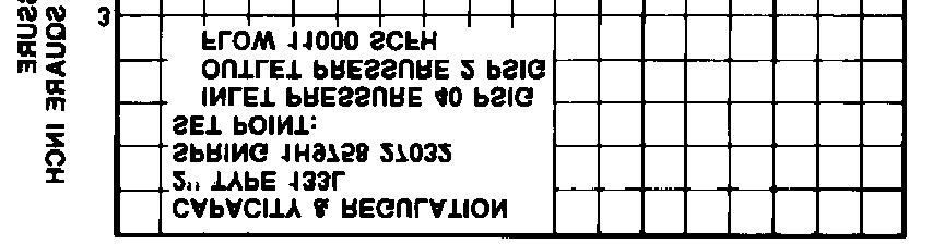
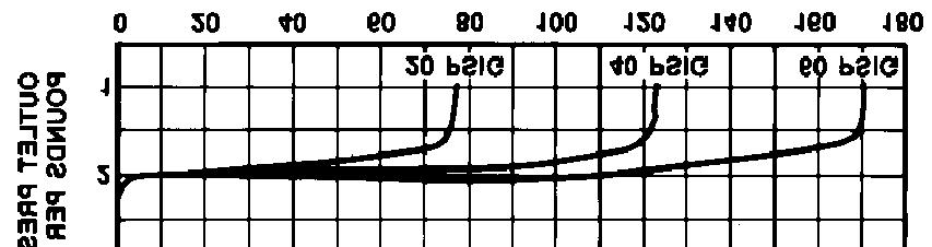
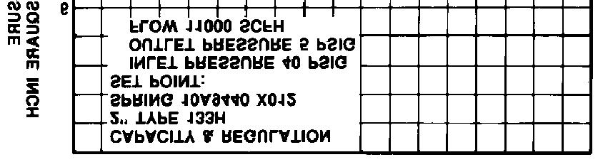
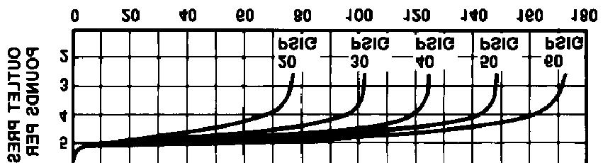
9 21A0871-A 21A0868-A 21A0865-A 21A0869-A 21A0866-A 21A0870-A NOTE: FLOW RATE CUBIC FEET PER HOUR 0.6 SPECIFIC GRAVITY GAS AT 14.7 PSIA & 60_F 21A0867-A C0744 Figure 6. Capacity Curves Full-Capacity Constructions 9


10 23A1336-A 23A1332-A 23A1334-A 23A1333-A 23A1337-A 23A1335-A NOTE: FLOW RATE CUBIC FEET PER HOUR 0.6 SPECIFIC GRAVITY GAS AT 14.7 PSIA & 60_F C0745 Figure 7. Capacity Curves Restricted Capacity Constructions 10
11 Table 7. Type 133HP Regulator 100% Capacities in Thousands of CFH of (0.6 Specific Gravity Gas at 14.7 Psia and 60_F) RANGE, CONTROL SPRING NUMBER & COLOR SETTING (1) 2 INCH BODY SIZE 1.91 INCHES (48.5 mm) ORIFICE SIZE DROOP FROM SETPOINT Psig Bar Psig Bar 10% 30% (0.14 to B8632X Yellow (0.14 to B8633X Orange to 20 psig (0.69 to F Tan RANGE, CONTROL SPRING NUMBER & COLOR SETTING (1) 2 INCH BODY SIZE 1.91 INCHES (48.5 mm) ORIFICE SIZE DROOP FROM SETPOINT Psig Bar Psig Bar 10% 30% to 30 psig (1.4 to F Pink to 40 psig (2.1 to E Dark Gray to psig (2.8 to E Light Green to 60 psig (3.4 to E White Outlet pressure setting was made at approximately 10% of the maximum capacity for the listed conditions. 2. Shaded area is equal to maximum flow capacity. 11
12 Table 8. Type 133HP Regulator 25% Capacities in Thousands of CFH of (0.6 Specific Gravity Gas at 14.7 Psia and 60_F) RANGE, CONTROL SPRING NUMBER & COLOR SETTING (1) 2 INCH BODY SIZE 1.91 INCHES (48.5 mm) ORIFICE SIZE DROOP FROM SETPOINT Psig Bar Psig Bar 10% 30% (0.14 to B8632X Yellow (0.34 to B8633X Orange to 20 psig (0.69 to F Tan RANGE, CONTROL SPRING NUMBER & COLOR SETTING (1) 2 INCH BODY SIZE 1.91 INCHES (48.5 mm) ORIFICE SIZE DROOP FROM SETPOINT Psig Bar Psig Bar 10% 30% to 30 psig (1.4 to F Pink to 40 psig (2.1 to E Dark Gray to 50 psig (2.8 to E Light Green to 60 psig (3.4 to E White Outlet pressure setting was made at approximately 10% of the maximum capacity for the listed conditions. 2. Shaded area is equal to maximum flow capacity. 12
13 Table 9. Type 133HP Regulator 40% Capacities in Thousands of CFH of (0.6 Specific Gravity Gas at 14.7 Psia and 60_F) RANGE, CONTROL SPRING NUMBER & COLOR SETTING (1) 2 INCH BODY SIZE 1.91 INCHES (48.5 mm) ORIFICE SIZE DROOP FROM SETPOINT Psig Bar Psig Bar 10% 30% (0.14 to B8632X Yellow (0.34 to B8633X Orange to 20 psig (0.69 to F Tan RANGE, CONTROL SPRING NUMBER & COLOR SETTING (1) 2 INCH BODY SIZE 1.91 INCHES (48.5 mm) ORIFICE SIZE DROOP FROM SETPOINT Psig Bar Psig Bar 10% 30% to 30 psig (1.4 to F Pink to 40 psig (2.1 to E Dark Gray to 50 psig (2.8 to E Light Green to 60 psig (3.4 to E White Outlet pressure setting was made at approximately 10% of the maximum capacity for the listed conditions. 2. Shaded area is equal to maximum flow capacity. 13
14 Table 10. Type 133HP Regulator 60% Capacities in Thousands of CFH of (0.6 Specific Gravity Gas at 14.7 Psia and 60_F) RANGE, CONTROL SPRING NUMBER & COLOR SETTING (1) 2 INCH BODY SIZE 1.91 INCHES (48.5 mm) ORIFICE SIZE DROOP FROM SETPOINT Psig Bar Psig Bar 10% 30% (0.14 to B8632X Yellow (0.14 to B8633X Orange to 20 psig (0.69 to F Tan RANGE, CONTROL SPRING NUMBER & COLOR SETTING (1) 2 INCH BODY SIZE 1.91 INCHES (48.5 mm) ORIFICE SIZE DROOP FROM SETPOINT Psig Bar Psig Bar 10% 30% to 30 psig (1.4 to F Pink to 40 psig (2.1 to E Dark Gray to 50 psig (2.8 to E Light Green to 60 psig (3.4 to E White Outlet pressure setting was made at approximately 10% of the maximum capacity for the listed conditions. 2. Shaded area is equal to maximum flow capacity. 14
15 Installation The regulator may be installed in any position but is normally installed with the actuator portion vertical above the body portion. Flow through the body must be in the direction indicated by the flow direction arrow cast on the body portion. A downstream control line is required for operation of the regulator. A remote vent line may be required for some installations. Vent openings must be protected against the entrance of rain, snow, insects, or any other foreign material that may plug the vent. External dimensions are shown in figure 9. Ordering Information When ordering, specify: Application 1. Type of gas being controlled (natural gas, air, etc.): list any factors such as impurities in the gas that may affect compatibility of the gas with the regulator trim parts. 2. Specific gravity of the gas 3. Temperature of the gas 4. Range of flowing inlet pressures to regulator 5. Outlet pressure 6. Flow rates a) Minimum controlled flow b) Normal flow c) Maximum flow 7. Line size and end connection size of adjacent piping Regulator Refer to the Specifications table on page 2. Carefully review the description to the right of each specification and in the referenced tables. Specify the desired selection wherever there is a choice to be made. Always specify the regulator type number. 1/4INCH STREET ELBOW POSITION 1 (STANDARD) POSITION 2 POSITION 3 POSITION 4 D C STANDARD E 27B5342A F VENT ORIENTATION Figure 8. Type 133HP Assembly Positions for Body/Spring Case Orientation 15
 2-INCH ANSI CLASS 125 FLAT-FACED FLANGES 2-INCH ANSI CLASS 150 RAISED-FACE FLANGES 6.94 (176) 9.88 Ø (251) Types 133H, 133L and 133Z Regulator 2-11 1/2 NPT 2.12 (53.8) 14.88 (378) A6981 5.00 (127.")
16 14.12 (358.6) 1-8 NPT SCREENED VENT 3/4-14 NPT CONTROL CONNECTION (339.9) 7.94 (201.7) 4.38 (111.3) 5.00 (127.0) (254.0) 2-INCH ANSI CLASS 125 FLAT-FACED FLANGES 2-INCH ANSI CLASS 150 RAISED-FACE FLANGES 6.94 (176) 9.88 Ø (251) Types 133H, 133L and 133Z Regulator /2 NPT 2.12 (53.8) (378) A (127.0) (254.0) TYPE Y602-7 VENT 4.56 (116) 1/4-18 NPT DOWNSTREAM CONTROL LINE A (127) (254) Type 133HP Regulator 2-INCH ANSI CLASS 125 FLAT-FACED FLANGES 2-INCH ANSI CLASS 150 RAISED-FACE FLANGES INCH (mm) Figure 9. Dimensions Fisher, Fisher-Rosemount, and Managing The Process Better are marks owned by Fisher Controls International, Inc. or Fisher-Rosemount Systems, Inc. All other marks are the property of their respective owners. EFisher Controls International, Inc. 1972, 1991; All Rights Reserved, The contents of this publication are presented for informational purposes only, and while every effort has been made to ensure their accuracy, they are not to be construed as warranties or guarantees,express or implied, regarding the products or services described herein or their use or applicability. We reserve the right tomodify orimprove thedesigns orspecifications ofsuch productsat anytime withoutnotice. For information, contact Fisher Controls: Marshalltown, Iowa USA Gallardon, France Sao Paulo Brazil Singapore Printed in U.S.A.