AE 481W Thesis Proposal
|
|
|
- Shannon Owen
- 5 years ago
- Views:
Transcription


1 AE 481W Thesis Proposal I I Advisor: Dr. Treado UNIVERSITY OF CALIFORNIA SAN DIEGO RADY SCHOOL OF MANAGEMENT LA JOLLA, CA
2 TABLE OF CONTENTS Executive Summary.3 Mechanical System Overview..4 Design Objectives, Requirements, & Influences..6 Mechanical System Design & Operation...7 Mechanical System Redesign Breadth Topics.. 12 Integration & Coordination.13 Spring 2010 Proposed Schedule 14 References 15 2
3 EXECUTIVE SUMMARY This report is to establish a redesign of the mechanical system for the UCSD Rady School of Management s mechanical system in response to my findings in the first three technical reports. If approved, it will be the basis for my redesign in the spring of Several different redesign options were investigated and then narrowed down to determine the best possible option. The option that is proposed is a dedicated outdoor air system with active chilled beams, with the possible addition of a ground source heat pump. These systems will be researched and evaluated in the spring. Along with the mechanical system redesign, two breadth topics will also need to be discussed. The first topic is concerned with the construction management that will be required to make the proposed alterations to the building. This will include time and cost of construct, as well as help provide a payback period for the new systems. The second topic is concerned with the changes in the electrical system that will come about from these alterations. There is a tentative schedule included that lays out the progression of work that will need to happen in the spring. 3
4 Mechanical System Overview PART I Mechanical System Overview The UCSD Rady School of management is a roughly 91,000 SF, state of theart, learning facility dedicated to the development of the next generation of science and technology business leaders. This building is home to a combination of learning/research facilities, faculty offices, and student services offices. Some sustainable design principles taken into consideration for this project were: Efficient lighting, recycled materials, and natural ventilation. In addition to these features, they plan on utilizing solar energy with photovoltaic panels that are to be installed in the future. The mechanical load on the building will be mainly cooling load because of the building s location and usage. Air is distributed to the interior spaces by an over head VAV system with reheat coils. The VAV system is supplied by three AHUs that are roof mounted to maximize the usable program area. In addition to the AHUs, there are seven fan coil units that utilize the building chilled water loop to maintain the design temperature in rooms with high heat generation. AHU s The facility utilizes three roof mounted air handling units with variable frequency drives. The air handlers supply air at 53 O F through the use of chilled water cooling coils and utilize a minimum of 30% outdoor air. They have also been oversized in order to leave room for future expansion. AHU 1 has a capacity of 40,000 CFM and serves the northern wing of the building, serving mainly classrooms and faculty offices. The current designed air flow is 33,660 CFM at maximum load with 19,368 CFM of outdoor air required. AHU 2A and AHU 2B are combined into one system and work together cool the other two remaining wings of the building. These AHU s are similar to AHU 1, but they have a slightly smaller capacity. They can each handle 35,000 CFM, so together the combined system can handle up to 70,000 CFM. The current designed airflow on these air handlers is only 60,610 CFM at maximum load with 22,662 CFM of outdoor air required. FCU s There are a total of seven fan coil units located throughout the building. These units are located in rooms with high amounts of heat generation such as, the server room, elevator equipment room, and main electrical room, to help maintain them at the designed temperature. They are also located in the main and intermediate cross 4
5 connects, which act as hubs for connecting telecommunications equipment. The FCU s take air in at 80 O F, cool it down to 55 O F and re circulate it throughout the room in order to maintain acceptable ambient temperature. Central Utility Plant (CUP) The CUP is designed with one 3,000 ton York OT steam turbine driven centrifugal chiller which handles the majority of cooling requirements, as well as, a 2,000 ton York YK electric centrifugal chiller to handle peak loads and off hour requirements. The combination of a steam and electric chillers is to provide UCSD with maximum energy efficiency and flexibility. Chilled Water System Chilled water is supplied by the university s CUP at 42 O F and circulated throughout the building by a 445 GPM base mounted pump, as well as a 50 GPM in line pump for off hour loads. The chilled water supplies the 3 rooftop air handlers, as well as the seven fan coil units. Hot Water System Hot water is supplied by a Bell & Gossett water to water U tube heat exchanger. The heat exchanger can heat 145 GPM of water from 140 O F to 180 O F with the use of high temperature water supplied by the CUP at 350 O F and 60 GPM. The hot water is then supplied to the building s VAV reheat coils and domestic water heater by a 145 GPM base mounted pump. Exhaust Fans There are a total of 6 roof mounted exhaust fans in the building to serve the bathrooms, electrical closets, and mechanical room. The fan serving the mechanical room moves between 600 and 2,000 CFM, and all others are designed for 4,000 CFM. 5
6 Design Objectives, Requirements, & Influences PART II Design Objectives, Requirements, & Influences The Rady School of Management is designed to be a state of the art networking and videoconferencing facility, as well as the School of Management s education and research base. It is designed to encourage interactivity between students, business leaders, and faculty. The building s mission is to develop entrepreneurs and innovators into successful science and technology leaders. The building is located on the northern part of campus and therefore has spectacular sights over the Pacific Ocean and surrounding mountains. The exterior glazing makes for extraordinary views, as well as provides ample daylighting. It was a requirement of the University that this facility be designed to LEED certification standards. The facility was designed to be equivalent to a LEED silver certified building, although certification was never applied for. Later in the report an overview will be given of the LEED certification points, and verified that this facility is in fact a LEED silver equivalent. In addition to these requirements, this building must also be designed to be in compliance with ASHRAE Standard 90.1, which deals with minimum envelope requirements, as well as defines standards for a litany of mechanical system components. Also, the minimum outdoor air requirements as defined by ASHRAE 62.1 must also be met. As always, cost is a factor, too. There is always a desire to design a system with a small operating cost, but most of the time this means a higher first cost, which is not always desirable for the building owner. Also, this is a public building, which tend to go to the lowest bidder. In this case though, it seems they have a good balance between first cost and operational cost, probably due to design incentives. This point will be delved into deeper later in the report. Along with all of these design criteria, it was necessary to leave extra space for expansion of the building in the future. 6
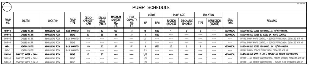
7 Mechanical System Design & Operation PART III Mechanical System Design and Operation The Rady School of Management has a very simple and straightforward design. For heating purposes there is a high temperature water loop and for cooling purposes there is a chilled water loop. It is so simple because the central utility plant is in charge of delivering chilled water and high temperature water, so there is no need for an on site chiller plant or boilers. Chilled Water System For cooling purposes, chilled water is delivered to the building, from the University s central utility plant, at 42 o F and a maximum rate of 453 GPM. Two pumps, equipped with variable frequency drives (VFDs), are then used to circulated the water to the rooftop air handling units, as well as the building s seven fan coil units. One pump is base mounted and has a maximum design capacity of 445 GPM. This pump is designed to do all of the pumping during normal operational hours. To reduce electricity consumption, there is also an in line pump with a maximum design capacity of 50 GPM to keep water circulating to any of the building s required loads during off hour operation. Differential pressure transmitters (DPTs) control the VFDs that regulate the pumps flow rates. These DPTs are located on the supply and return lines coming from each of the three air handling units. There are also DPTs located on each of the VAV boxes to regulate airflow to the zones. The FCUs are regulated by thermostats and motorized control valves. For a schematic of the chilled water loop, please refer to Appendix A, Fig. A 1. Schedule information on the AHUs, FCUs, and VAV boxes can be found in Appendix B. Chilled water pump data can be found in Fig VI 1 below, as well as in Appendix B, Table B.3. Fig. VI 1 Chilled Water Pump Schedule DESIGN CAPACITY PUMP SYSTEM PUMP TYPE (GPM) DESIGN HEAD (FT) CHWP-1 CHILLED WATER BASE MOUNTED CHWP-2 CHILLED WATER INLINE
8 Hot Water System For heating purposes, high temperature water is delivered to the building, from the central utility plant, at 350 o F and a rate of 60 GPM. This high temperature water is designed to pass through the shell side of the water to water U tube heat exchanger to increase the temperature of the building s hot water that runs through the tube side. The shell side water leaves the heat exchanger at 250 o F and is circulated back to the CUP. On the tube side of the heat exchanger, water enters at 140 o F and a maximum rate of 145 GPM. After heat transfer between the shell and tube, the water exits the heat exchanger at 180 o F. This water is used to heat domestic water, and also supply the buildings VAV box reheat coils. The hot water is delivered to these systems by a base mounted pump with a design capacity of 145 GPM and a VFD. The VFD regulates the pump speed based on differential pressure transmitters, just like the chilled water pumps. For a schematic of the hot water loop, please refer to Appendix A, Fig. A 2. Schedule information on the heat exchanger, domestic water heater, and VAV boxes can be found in Appendix B. Data on the hot water pump is located in Fig. VI 2 below, and can also be found in Appendix B, Table B.3. Fig. VI 2 Pump Schedule PUMP SYSTEM PUMP TYPE DESIGN CAPACITY (GPM) DESIGN HEAD (FT) HWP-1 HEATING WATER BASE MOUNTED
9 Mechanical System Critique Part IV Mechanical System Critique After thorough evaluation of the s mechanical system, it seems like the design team has done a superb job. They have created a system that works efficiently with an operating cost of only $1.91/ft 2. They managed to do this while still maintaining a low first cost at $ It worked in their favor that the building is supplied with cheap energy by the University s central utility plant, but even in light of this, they did not neglect to create a highly efficient system. The building exceeds the minimum requirements by a fairly large amount in several categories. It is 28% above the Title 24 requirements and 38% above ASHRAE 90.1 standards. It is no doubt a very efficient system and improving on the design will be a tough task. One thing to look into will be the feasibility of using different sustainability principals. They plan to install a solar array in the future, and evaluation of a solar system might be something to look into. Another possibility would be to add more sophisticated controls to the system, or maybe alter some architectural features. 9
10 Mechanical System Redesign PART V Mechanical System Redesign I started off by researching the various types of mechanical systems. I needed a system that would work for this type of building and in this environment. I found several viable options, but I needed to choose the best type of system for this application. Some options I considered were: on site chiller/boiler, waste heat recovery units, natural ventilation, and a chilled beam system. When selecting which option I wanted to go with, I chose the option that seemed like it could save the most energy in this application, and also reduce emissions. Some other factors that I wanted to take into account were first costs, operating costs, payback period, and ease of maintenance. After weighing all of my option, I narrowed my options down. There were 3 options that stood out as the most viable. These three options were: a ground source heat pump, a dedicated outdoor air system, and active chilled beams. Active Chilled Beams There are many reasons why active chilled beams would be effective in this situation. First of all, water has a higher heat capacity than air, therefore much less of it must be delivered in order to achieve the same amount of heating/cooling. This also leads to smaller ducts, and VAV boxes are eliminated all together. Taking this into account, the interstitial space could be much smaller. This would reduce floorto floor heights and in turn the cost of construction. This type of system also tends to lead to warmer chilled water temperatures for cooling, and cooler hot water temperatures for heating. Also, a typical active chilled beam system only requires CFM/ton. This leads to smaller AHUs and reduces the fan energy requirements. Since this system mainly deals with sensible loads, it would work great in combination with a DOAS system, which greatly reduces latent load. For this reason, it would also be very effective in replacing the existing fan coil units in rooms with high heat generation and a mainly sensible load. This seems like a great alternative to the current VAV system. It should have a much lower first cost, as well as a lower operating cost. Dedicated Outdoor Air System (DOAS) Dedicated outdoor air systems are desirable for several reasons. One of the main reasons for choosing it was that it works great in conjunction with a chilled beam system. This is because they greatly reduce the latent load by eliminating the moisture associated with the ventilation air. They also greatly increase indoor air 10
11 quality, and therefore the productivity of the building occupants. In addition to this, DOAS systems tend to have a lower first cost and are easier to maintain. Ground Source Heat Pump The main reason I considered using a ground source heat pump is because it will reduce the amount of work required to heat the building s water supply. This would help reduce the carbon footprint of the building, as well as decrease the energy consumption. This system would not replace any existing mechanical equipment, but it could reduce the required size of it. Also, I think it would probably work well in conjunction with the solar array that is scheduled to be installed. Another reason this is a viable option is because it could also work with a chilled beam and DOAS system. This would allow for the incorporation of all three design options, and therefore a great reduction in energy consumption and carbon footprint. 11
12 Breadth Topics PART VI Breadth Topics Along with the redesign of the mechanical system, it is necessary to look into other aspects of the design in order to make a well educated decision. The topics I will investigate include construction management and the electrical system of the building. Construction Management Breadth If these systems are to be installed in the building, it is necessary to calculate the cost and time of construction. By analyzing the cost and impact on schedule that each of these systems will cause, it should become evident which system, or combination of systems, will be the most practical. Chilled beam and DOAS systems usually have a low cost of installation, but ground source heat pumps do not. This breadth topic will be most helpful in deciding if GSHPs should be used, as well as the payback period for the installed system. Electrical Breadth If any or all of these systems were installed in this building it should significantly reduce electrical loads. Many mechanical system components will either be reduced in size, or eliminated all together. This will result in a smaller electrical load and less wiring required. In addition to resizing the wiring, circuit breakers could also be reduced in size. This will help calculate how much this type of system can save in terms of material, and help demonstrate the how much changing the mechanical system can impact electrical design. 12
13 Integration & Coordination PART VII Integration & Coordination Three possible system alternatives have been proposed along with a construction management and electrical breadth. In order to analyze which systems should be incorporated in the building, there will need to be a substantial amount of research and calculations. In order to stay on track with the redesign process, a plan of attack needs to be created for the spring 2010 semester. The initial stages of redesign will need to include extensive research into the three types of systems proposed. Case studies and technical papers on the topics of these system s success or failures will need to be read through. After performing extensive research, calculations will need to be done in order to quantify how much the system has been improved. This will include running another block analysis energy simulation using Trane TRACE 700. These energy model results will hopefully verify my initial proposal and result in a reduction of energy consumption. Using these results, I will be able to calculate the expected annual savings and reduction in carbon footprint. After finishing the mechanical redesign, I will then be able to delve into my breadth topics. For the construction management breadth, cost of installation will be calculated. This will then help determine the payback period with the use of my energy model results. Also, time of construction will be calculated and a proposed gantt chart for each of the construction activities will be created. The electrical breadth will include an evaluation of all new mechanical system components and determine if these new systems can create a substantial change in electrical design. This will help establish the necessary alterations that need to be made to the electrical system. After this is complete, an analysis will be done on the cost/savings of the new electrical system, as compared to the old one. 13
14 Spring 2010 Proposed Schedule PART VIII Spring 2010 Proposed Schedule The following is a proposed schedule for the redesign of the mechanical system and aforementioned breadth topics. The schedule has laid out the redesign process from start to finish with some extra time included to allow for some flexibility in the schedule. Spring 2010 Tentative Schedule Task Start Date Finish Date Duration Research Proposed Systems 12/21/09 1/21/10 30 Days Create TRACE 700 Energy Model 1/22/10 1/31/10 10 Days Analyze Energy Model Results 2/1/10 2/6/10 5 Days Design/Size New System 2/7/10 2/17/10 10 Days Work on CM Breadth 2/17/10 2/24/10 7 Days Analyze CM Breadth and New Design 2/25/10 3/2/10 5 Days Work on Electrical Breadth 3/2/10 3/9/10 7 Days Finish Calculations 3/9/10 4/5/10 24 Days Prepare Presentation 4/6/10 4/13/10 7 Days Presentations 4/14/10 4/21/10 7 Days 14
15 References ASHRAE Handbook, HVAC Systems and Equipment. American Society of Heating, Refrigeration, and Air Conditioning Engineers, INC., Atlanta, GA. DOAS & ABC Research
16 16
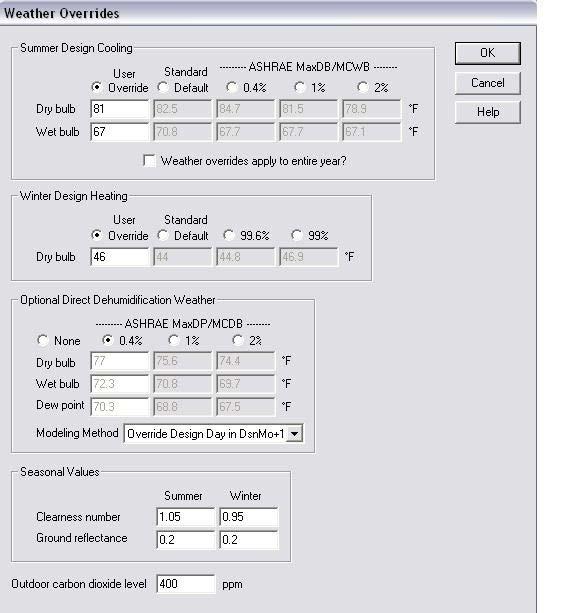
17 APPENDIX Weather Overrides 17
18 18

19 System Schematic 19

20 Typical Office Template 20

21 Typical Classroom Template 21

22 Typical Construction Template 22

23 Airflow Template U value Roof Walls Glass 0.3 Typical U Values 23
24 24
25 REFERENCES ASHRAE. 2005, 2005 ASHRAE Handbook Fundamentals. American Society of Heating Refrigeration and Air Conditioning Engineers, Inc., Atlanta, GA Ellerbe Becket Specifications, Mechanical, Electrical, and Plumbing Drawings. 800 La Salle Ave, Minneapolis, MN RegionalGridEmissionFactors2007.pdf 25