CO 2 Geological Storage In Salah Algeria Sustainable Development Project
|
|
|
- Amber Gibson
- 5 years ago
- Views:
Transcription
1 JIP ( Joint Industry Project ) CO 2 Geological Storage In Salah Algeria Sustainable Development Project N.Bounoua SONATRACH 1
2 JIP ( Joint Industry Project ) Summary Motivations Why Geological Storage? CO 2 injection In Salah Gas Project Objectives Main Focus and Challenges Technologies to be used Final Remarks 2


3 JIP ( Joint Industry Project ) Motivations : GHG & Earth Climate Evolution Natural + anthropogenic activities Last Half Billion Years 3 Source : SEED
4 JIP ( Joint Industry Project ) GHG & Earth Climate Evolution Observation : Period CO2 Concentration In the Atmosphere Previous Cycles Current Cycle < 300 ppm > 380 ppm This situation indicates that the emitted volumes are exceeding the natural recycling capacity of the earth. Action : Coordinated measures for greenhouse gas emission limitations are needed. 4
5 JIP ( Joint Industry Project ) Possible Mitigation Measures Energy Efficiency Improvement, Renewable Energies Development Natural Gas Flaring Elimination CO2 Geological Storage 5
6 Gas Flaring Elimination In Algeria Flaring Rate 7 % Total Recovery targeted for 2012 comply with nat. regulation
7 JIP ( Joint Industry Project ) Why CO 2 Geological Storage? Carbon Distribution G tonnes Fossil Energies Sedimentary Rocks (Carbonates) Organic Material Atmosphere 825 Source : Actu-Environnement CO2 Geological storage reinject a certain amount carbon associated to fossil energies in the sedimentary layers, From where these energies are generally produced. This will help to stabilize the carbon quantity in the atmosphere 7
8 JIP ( Joint Industry Project ) Possible Storage Capacities Reservoir Type Storage Potential (Gt) Saline Aquifers ( In Salah) Depleted HC Reservoirs Abandoned Coal Mines Low Source : Actu-Environnement 8

9 In Salah Gas Project Hassi R Mel <0.3% CO 2 Krechba 38 60km km For Transport Specifications Reg 24 62km 24 13km Tegentour Gas CO 2 content 5-10% Garet el Befinat Hassi Moumene In Salah Gour Mahmoud 9
10 In Salah: 25-Year CO 2 Profile 1,800,000 CO2 Emissions by Source 1,600,000 1,400,000 1,200,000 1,000, ,000 CO 2 from Produced Gas CO2(Injected) Flaring - Well Testing Flaring - Process Fugitives - Process Venting - Non CO2 Re-Injection Venting - Storage Tanks Combustion - Drilling Combustion - Emergency Power Combustion - Compression Combustion - Power Generation Combustion - Process Heat 600, , ,000 CO 2 from Heat & Power Generation 0 More than 17 Mt of CO2 will be produced by Decarbonation The J.V. has decided to reinject safely this important volume of CO2, instead of flaring it in the atmosphere. Year 10

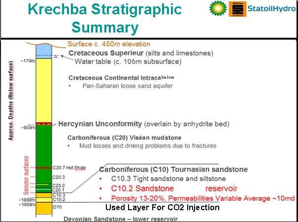
11 CO 2 Storage Concept Amine C02 removal Gas production (4 wells) Gas to Deshydratation and transport CO 2 injection (3 wells) Sand Sequence 900 m Seal of the Trap Confirmed by the presence of a Gas field currently under production 1800 m Mudstones 900 m 11 Carbonifous Saline aquifer
12 12
13 Joint Industry Project DOE US CO2REMOVE-EU Fund & technical Contributors Open to other Cont. Executive Board Chair Members Scientific Advisory Board From University Programme Manager Monitoring Programme Modelling & Verification R&D Communica tions Field Operations 13
14 JIP ( Joint Industry Project ) Objectives Provide assurance that secure CO 2 geological storage can be cost-effectively verified and that long-term assurance can be provided by short-term monitoring. Demonstrate that industrial-scale of CO 2 geological storage is a viable GHG mitigation option. Contribute for the regulation and verification of the CO 2 geological storage, allowing eligibility for Carbon Credits 14
15 Main Focus and Challenges To reach Objectives Data Acquisitions and Studies have been Identified The Aim : 1: Refine Reservoir Model 2: Characterize the overburden, Seal across the field 3: Confirm Well Integrity, Monitoring Well Head, Cement, Casing 15
16 Completed Operations Risk Management Analysis Surface Facilities 3D Seismic Interpretation Reservoir Modeling Drilling 3 Horizontal Injector Wells Geomecanical / Geochemical Studies (on progress) Aquifer and Soil CO2 Baselines Determination Radar Satellite Images, Acquisition and Analysis 16
 Breakout Dominant NW-SE")

17 Borehole Log Images KB-14 C20.7 Interval (Overburden) Breakout Dominant NW-SE Direction Bedding ( structural analysis) Nat. Fractures Characterization Density,Orientation,ConductivityI n situ Stress Determination Schlumberger 17
18 Krechba Well Locations KB Kb-5 CO2 Injectors Kb-502 Kb-503 Kb-502 Gas Producers Well Trajectory Kb-503 Kb-14 Kb-CA Kb-8 Kb-4 Kb-9z Kb-11 Kb-CB Kb Kb-501 Kb-12 Kb-501 Kb-6 Kb-CC Full Gas Column Smax Fractures Strike Kb-10 Kb-7 Kb-13 Kb-CE Injection capacity : 2Msm3/d Kb-1 Gas-Water Contact metres below Mean Sea Level ~1800 metres below Ground Level Spheroid: Projection: Datum: Clarke 1880 UTM Zone 31N N Sahara Meters 5000 First Gas Development Well Locations Production Well CO2 Injection Well Appraisal Well Locations Kb-1 18


19 Radar Satellite Images Processed Time Lapse Images Kb-503 Kb-503 Kb-5 Kb-502 Kb-5 Kb-502 Relative Uplift Up to 5mm Sealed Fault? Seen on Seismic Kb-14 Kb-11 Krechba Plant Kb-12 Kb-14 Kb-11 Kb-12 Kb-501 GWC useful information will be used to update the permeability distribution model. Kb-13 19
20 Short Term Programme 3D Seismic ( wide azimuth ) for Reservoir & Overburden characterization Micro-seismic for Fractures Detection Drilling 4 Shallow Wells for Aquifer Monitoring Tiltmeter Measurements for Satellite Image Calibration CO 2 Soil Monitoring Testing New CO2 Resistant Cements Micro-Biology Study 20
21 Final Remarks Regarding the high injection capacity in a short term, Geological Storage offers an interesting but technically challenging alternative for GHG mitigation. Industrial-scale Demonstration Projects (like In Salah) are required to gain confidence in the technique, understand the costs and develop policies required for widespread CCS deployment. With Its success, the world will continue to rely on fossil fuels for most of its energy needs for the for-seeable future. 21
22 JIP ( Joint Industry Project ) Thank You For Your Attention 22