Products Solutions Services. Coriolis. Promass
|
|
|
- Lindsey Beasley
- 5 years ago
- Views:
Transcription


1 Products Solutions Services Coriolis Promass Slide 1
 T = Temperature Slide")
2 Coriolis_Promass Coriolis Measuring Principle Direct Measurement = Phase shift m = Mass flow ~ m f R ~ ~ T f R = Resonance frequency = Density = Resistance (PT1000) T = Temperature Slide 2
3 Coriolis_Promass Overview of calculated values V = Volume flow V = m/ V N = Standard volume flow = Volume flow at fixed p and T V N = m/ N (note: N is a fixed value for each fluid) c = Concentration Concentration can be calculated from density μ,η = Viscosity Viscosity can be calculated from oscillation damping. Viscosity measurement is only available with the Promass 83I. Slide 3
4 Coriolis_Promass Why Measure Mass Temperature / Pressure Volume 1 Volume 2 Mass 1 = Mass 2 Mass 1 Volume 1 Mass 2 Volume 2 Slide 4


5 Coriolis_Promass Traditional Mass Measurement Discontinuous, direct Continuous, indirect V = Volume flow r = Density m = Mass flow Slide 5

6 Coriolis_Promass Standard 2 nd Containment Enhanced Process Security Additional safety measure for corrosive/abrasive fluid Slide 6

7 Coriolis_Promass Vibration effect Fisher-Rosemount ELITE CMF100 Effect of interference vibration, 0.5g, zero flow, tubes empty 10 zero stability [kg/h] fr equency [Hz] Coriolis flowmeters show high instability if pipe vibration is the same as operating frequency of measurement tube Slide 7
8 Coriolis_Promass Vibration effects: How it should be E+H Promass DN25/1" Effect of interference vibration, 0.5g, zero flow, tubes empty 10 zero stability [kg/h] frequency [Hz] Inherent zero stability by design Rigid secondary enclosure Sophisticated welding and manufacturing techniques High resonant frequency (>500 Hz) If external noise can t get in and cause zero problems, then vibration doesn t get out and cause crosstalk problems between adjacent meters. Slide 8


9 Coriolis_Promass Less Installation Constraint Compact design Vertically or horizontal installation. Less installation constraint 3 Slide 9
 Slide")
10 Coriolis_Promass Self Draining Design No liquid stays inside No sedimentation of solids No corrosion Less sensitive to clogging EHEDG certified, 3A approved (Promass P - Pharmaceutical application) Slide 10


11 Coriolis_Promass Installation Guidelines Coriolis flowmeters DO NOT require straight inlet or outlet runs Elbow, valves or pumps upstream do not affect the performance of coriolis Full pipe Best installation: In vertical pipeline with flow streaming upwards Good alternative: Horizontal orientation on a low point in a pipeline Slide 11
12 Coriolis_Promass Installation Guideline Consider the following restriction: Avoid installation at the highest point of a pipeline. Avoid installation directly upstream of a free pipe outlet in a vertical pipeline. If installation before a free pipe outlet is inevitable: Decrease nominal outlet diameter (Pipe restrictor or an orifice plate). Consult operating manual for recommended orifice sizes. Slide 12
 Entrained gas in liquids: Do not install the curve pointing upwards.")
13 Coriolis_Promass Installation Guidelines Entrained gas Entrained solids With curved measuring tubes and horizontal installation: Entrained solids in liquids: Do not install the curve pointing downwards. (Risk of accumulating solids) Entrained gas in liquids: Do not install the curve pointing upwards. (Risk of accumulating gas) Slide 13


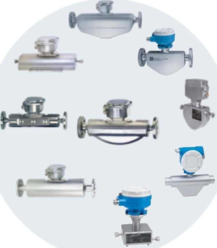

14 Coriolis_Promass Coriolis Mass Flow Measurement Product overview Promass Promass 80 Promass 83 Promass 200 Promass 100 Slide 14


15 Coriolis_Promass Proline Coriolis sensor models by industry Industry Promass F E S P I H A X O Cube mass Chemical Food and Beverage Life Sciences Oil and Gas Lead product industry optimized Supporting product for special applications Slide 15
 Measuring Error up to ± 0.10% o.")
 Nominal Diameter: DN 8 to 250 (3/8 to 10 )")
16 Coriolis_Promass Sensor Models Promass E Cost effective measuring device Measuring tube material: Stainless steel Process temperature up to 140ºC Nominal Diameter: DN 8 to 80 (3/8 to 3 ) Measuring Error up to ± 0.10% o.r Promass F Universal Solution Mass flow measurement up to 2200 t/h Measuring tube material: Stainless steel, Alloy C-22 High temperature version up to 350ºC Process pressures up to 100 bar (1450 psi) Nominal Diameter: DN 8 to 250 (3/8 to 10 ) Measuring error up to ± 0.05% o.r Slide 16
 Measuring Error up to ± 0.10% o.")
 Measuring error up to ± 0.10% o.")
17 Coriolis_Promass Sensor Models Promass A When every drop counts Measuring tube material: Stainless steel, Alloy C-22 Process temperature up to 200ºC Nominal Diameter: DN 1 to 4 (1/24 to 1/8 ) Measuring Error up to ± 0.10% o.r Promass I Multivariable solution Measuring tube material: Titanium Process temperature up to 150ºC Nominal Diameter: DN 8 to 250 (3/8 to 10 ) Measuring error up to ± 0.10% o.r DN 8 to 80 (3/8 to 3 ) Viscosity measurement with Promass 83I Slide 17
 Measuring Error up to ± 0.10% o.")
 Measuring Error up to ± 0.10% o.")
18 Coriolis_Promass Sensor Models Hygienic Application Promass S The food specialist Measuring tube material: Stainless steel Process temperature up to 150ºC Nominal Diameter: DN 8 to 50 (3/8 to 2 ) Measuring Error up to ± 0.10% o.r Promass P Specialized for life sciences industry Measuring tube material: Stainless steel Process temperature up to 200ºC Nominal Diameter: DN 8 to 50 (3/8 to 2 ) Measuring Error up to ± 0.10% o.r Features & Benefits CIP & SIP cleaning possibility Compliance to industry requirement : Promass S: EHEDG, 3-A & FDA approval Promass P: ASME BPE, ISPE, EHEDG, 3-A & FDA Slide 18


19 Coriolis_Promass Sensor Models - Oil & Gas Industry Promass X Four Tube Coriolis Flowmeter Maximum flow rates up to 4100 metric t/h All 316L NACE compliant stainless steel Accurate billing with fully traceable accuracy ±0.05% o.r. Process Connections: DN 300 to 400 (12 to 16 ) Promass O Corriosion resistance, robust and precise Fluid wetted parts are made of Super Duplex (25Cr duplex) Highest resistance to stress corrosion cracking Fully traceable accuracy ±0.05% o.r. Process temperature: -50 to +200ºC Nominal Diameter: DN 80 to 150 (3 to 6 ) Slide 19
 Measuring Error up to ± 0.10% o.")
20 Coriolis_Promass Sensor Models Chemical Industry Promass H For corrosive medium Measuring tube material: Tantalum, Zirconium Process temperature up to 200ºC Nominal Diameter: DN 8 to 50 (3/8 to 2 ) Measuring Error up to ± 0.10% o.r Slide 20

 Blind version optionally: 2-line back-lit")
21 Coriolis_Promass Proline 40: The basic Economical solution Communication 0/4..20mA; 0...1kHz HART Service interface (Connection to Tooling) Up to 3 cable glands Human Machine Interface (HMI) Blind version optionally: 2-line back-lit display in plain text Measuring values m, V Data storage S-DAT Slide 21
22 Coriolis_Promass Promass 80: The Standard Transmitter Communication 0/4..20mA; 0...1kHz HART + Profibus PA Service interface (Connection to Tooling) Up to 5 cable glands Human Machine Interface (HMI) Quick Setup for a fast and easy commissioning Push-button operation 2-line back-lit display: Display in plain text Digital Com Slide 22 Measuring values m, V,, T Data storage S-DAT
 Human Machine Interface (HMI) Quick Setup for a fast and easy commissioning Touch Control")
 Batching functions Viscosity measurement and Advanced diagnostics Data storage S-DAT, T-DAT,")
23 Coriolis_Promass Promass 83: The High-End Transmitter Communication Flexible I/O-Modules HART, PA, DP, FF, Modbus Service interface (connection to Tooling) Human Machine Interface (HMI) Quick Setup for a fast and easy commissioning Touch Control operation allows programming without opening of electronics 4-line back-lit display Modular Software concept Concentration calculation (Brix, Plato, API, etc) Batching functions Viscosity measurement and Advanced diagnostics Data storage S-DAT, T-DAT, F-CHIP Slide 23


24 Coriolis_Promass Proline Coriolis and MID sensor models by industry Promass F E S P I H A X O Cube mass Promag P H Proline 80/83 Proline 100 transmitter Proline 200 transmitter Slide 24


 Measuring error: ± 0.25% o.r. Promass F 200 the proven multi talent Measuring tube material: 1.")
 Nominal diameters: DN 8 to 50 (3/8 to 2\") Measuring")
25 Coriolis_Promass 2-wire Technology Flow Measurement Benefits of 2-wire Easy integration, as per any other loop powered device; 4 20 ma HART protocol. Reducing complexity and standardizing integration. High operational safety in Ex areas due to intrinsically safe design (Ex ia) Reduced costs for installation and wiring Promass E 200 for basic application Measuring tube material: /904L Process temperature: 40 to +140 C ( 40 to +284 F) Nominal diameters: DN 8 to 50 (3/8 to 2") Measuring error: ± 0.25% o.r. Promass F 200 the proven multi talent Measuring tube material: /904L or Alloy C-22 for corrosive fluids Process temperature: 50 to +200 C ( 58 to +392 F) Nominal diameters: DN 8 to 50 (3/8 to 2") Measuring error: ± 0.10% o.r. Slide 25


26 Coriolis_Promass Proline 200: Intrinsic safety Safest approach to explosion protection. Compared with most other methods, inexpensive and easy to implement Intrinsically safe installation. Intrinsically safe design ma Housing can be opened in the field under power. Zone 1 Zone 2 Cl.I Div1 Slide 26 Cl.I Div2 Barrier (3rd party or E+H) Connection compartment & Electronic compartment are Ex ia (IS)


 Slide 27 Cable tray Ex SW d")
27 Coriolis_Promass Proline 200: Low installation costs 2-wire, loop powered makes life easier. Reduced cabling, less components thus savings installation time and costs. The 4-wire world Proline Ex d housing Power cable Ex d /Ex de Signal cable Ex ia (IS) (output) Slide 27 Cable tray Ex SW d (Flameproof) Lim armored cable Ex d/e (Flameproof) cable gland

, logging interval: 1 to 3600 sec.")
28 Coriolis_Promass Proline 200: HistoROM Data management HistoROM Basic Backup of transmitter data Min./max. values Totalizers List of max. 5 active errors with help instructions: Event list of max. 20 events event types: errors, resets, change of device configuration, download of new parameter set, power on/off, etc. HistoROM Extended Data logging max values, 4 channels (free assignment), logging interval: 1 to 3600 sec. visualization via display and FieldCare Event logging to max. 100 events. Sensor S-DAT Calibration data Diameter, serial number Slide 28


29 Coriolis_Promass HistoROM Example HistoROM functionality Electronic change during night shift The HistoROM is fixed in the housing (can not be lost or forgotten ) Slide 29


30 Coriolis_Promass HistoROM Configuration management Backup functionality: Backup / Restore / Duplicate in combination with local display Backup Restore Duplicate Measuring point 1 Duplicate Measuring point 2 Slide 30


31 Coriolis_Promass The smallest flowmeter Comparing two fullfeatured devices! Identical Measuring performance Accuracy Functionality Slide 31


32 Coriolis_Promass 3 housings to choose from IP69K External high pressure cleaning Hygienic ultra compact Hygienic Aluminum Promass: P/S/E/F/A/H/I/O/X 100 und Cubemass 100 Promag: H und P Slide 32


33 Coriolis_Promass HistoROM Configuration management Backup functionality with local HistoROM DAT and web server: enables: Backup / Restore / Duplication Backup Restore Duplicate Measuring point 1 Measuring point 2, 3, 4, etc. Slide 33
 Full device access without special tools or interfaces No special tools or interfaces required Saves time Slide")
34 Coriolis_Promass Operation with standard web browser All Proline four-wire devices feature integrated web server Fast and easy connection to the device via standard LAN cable (RJ45 connectors) Full device access without special tools or interfaces No special tools or interfaces required Saves time Slide 34

35 Coriolis_Promass Heartbeat Technology Product Options Heartbeat Monitoring Continuous output of measuring results and status information for the purpose of condition monitoring Heartbeat Verification Documentation of flowmeter functionality on demand, result is a verification report Heartbeat Monitoring Heartbeat Verification Pass / Fail Heartbeat Technology Diagnosis Slide 35


36 Coriolis_Promass Chemical: Hexane with rubber pellets Instrument: Industry: Promass 83F Chemical Fluid: Hexane with rubber pellets Reason: Clogging problems with PD flowmeters Benefits: No maintenance Self draining Advanced Diagnostics to detect built-up Slide 36

37 Coriolis_Promass Food: Malt, Honey, Palm Oil Instrument: Industry: Fluid: Promass 83I Food Honey, malt, palm oil Reasons: High viscosity Self draining Benefits: Low pressure drop Easy cleaning Slide 37

38 Coriolis_Promass Palm Oil: Alcohol Instrument: Industry: Fluid: Promass 83F Palm oil Alcohol Reason: Batching of alcohol into the reactor for esterification process. Benefits: Accurate batching for improved process control Slide 38
 compare to vortex flowmeter (±0.75% o.r.) Avoid additional cabling cost (if replace with 4-wire instruments) No inlet and outlet requirements Slide 39")
39 Coriolis_Promass Palm Oil: Alcohol Industry Requirement : Oleochemical : To replace Vortex flowmeter with a higher accuracy flowmeter Process Conditions: Fluid : Liquid alcohol Flowrate : kg/h Temperature : C Pressure : bar a Pipe Size : DN 50 Benefits: Higher measuring accuracy (±0.25% o.r.) compare to vortex flowmeter (±0.75% o.r.) Avoid additional cabling cost (if replace with 4-wire instruments) No inlet and outlet requirements Slide 39


40 Coriolis_Promass Palm Oil: Refined Palm Oil Instrument: Industry: Fluid: Promass 80F Palm oil Refined palm oil Reasons: Direct mass flow measurement Non-conductive liquid Benefits: Accurate inventory of storage tanks Slide 40

41 Coriolis_Promass Waste Water: % solids concentration Instrument: Industry: Fluid: Promass 83I Waste water Sewage, sludge 4 to 6% dry solid matter Reason: Concentration measurement Benefits: Precise in-line measurement of the currently existing concentration Display and output of the concentration value Possibility to determine degree of efficiency of gas production Easy installation of the measuring device Slide 41


42 Coriolis_Promass Petrochemical: Fuel Oil Instrument: Industry: Fluid: Promass 83F Petrochemical Fuel Oil Application: Truck loading Custody Transfer Benefits: Compact installation Accurate loading to/from truck Slide 42


43 Coriolis_Promass Offshore Crude Oil Test Separator Instrument: Industry: Fluid: Promass 83F Oil & Gas Crude Oil Reason: Previous turbine frequently clogged and was not self-draining Benefits: No maintenance Reliable measurement Self-draining Slide 43


44 Coriolis_Promass Oil& Gas: Corrosion Inhibitor Instrument: Industry: Fluid: Promass 83A Oil & Gas Corrosion Inhibitor Reasons: Control of flow rate Handling of pulsating flow due to piston pump Checking of Dosing Pump Benefits: Maintenance free flow measurement Saving of chemicals due to accurate dosing Slide 44
45 Coriolis_Promass Advantages & Limitations of Coriolis Advantages Direct, continuous mass flow measurement Multivariable: simultaneous measurement of mass flow, density and temperature High measuring accuracy (up to ±0.05% o.r.) Not affected by flow profile: no straight inlet/outlet runs required Limitations Pressure loss Measurement of single phase only Relatively high purchase price with others Slide 45
46 Products Solutions Services Any Questions? Slide 46
47 Products Solutions Services Vortex Prowirl Slide 47


48 Vortex - Prowirl Vortex Applications Liquids Steam Gases Slide 48
49 Vortex - Prowirl All you need for vortex measurement Transmitter f = Vortex frequency V = Volume flow f ~ V Bluff Body DSC Sensor Slide 49
50 Vortex - Prowirl Differential Switched Capacitor Sensor Electrode 1 Laser welding not in touch with process = no corrosion Electrode 2 Counter Electrode & Paddle have the same mass = perfectly balanced system = immune against vibrations Signal Amplitude Trigger Level The movement of the paddle generates sinusidal voltage change between Electrode 1 and 2 Slide 50
51 Vortex - Prowirl Measuring Range of a Vortex Flowmeter 1. Low flow limitation Reynolds number Vortex performs best at Re> 20,000 Increase of viscosity due to low process temperature lower Re number Small flow velocity lower Re number 2. Low flow limitation density/velocity Higher density and velocity creates stronger signal Slide 52
52 Vortex - Prowirl Effects of build-up and abrasion If no corrosion and operating at velocity's that could cause erosion (>50m/sec for abrasive gases) then the meter calibration is for life!!! Radius because of abrasion has no effect Amplifier or Sensor changes do not influence the performance! *** Life-Time-Calibration *** Build-up has no effect Slide 53
 Z-Axis Y-Axis X-Axis X-Axis Y-Axis Z-Axis Test proves vibration")
53 Vortex - Prowirl Vibration Immunity Acceleration (g) Frequency (Hz) Z-Axis Y-Axis X-Axis X-Axis Y-Axis Z-Axis Test proves vibration immunity: exceeds1g in all axes from 20 to 500 Hz Slide 54
 No effect on sensor performance or calibration Puddle of water is shot against the meter if the rupture disc bursts due to high pressure")
54 Vortex - Prowirl High Resistance to Water Hammer Water hammer simulator at University of Karlsruhe Tested with water slugs up to 100m/s (>350 km/h) No effect on sensor performance or calibration Puddle of water is shot against the meter if the rupture disc bursts due to high pressure Slide 55

55 Vortex - Prowirl Vortex Temperature Shock Test Heating sensor to +400ºC Shock cooling in water +25ºC 3X reheating to +400ºC and shock cooling in liquid nitrogen -196ºC Slide 56
56 Products Solutions Services Prowirl 200 Slide 57 Seou Wei
57 Prowirl the next step in vortex technology Bridge between current and new generation Transmitter New opportunities due to increased computing power (New transmitter housing and new housing strut) Sensor Proven & robust sensor All sensor parts remain the same (All meterbodies and DSC Sensors) Slide 58 Constantin Schoo


58 Prowirl the next step in vortex technology Prowirl 200 is optimized for steam applications! Wet steam detection USP! 100% steam quality 80% steam quality Worldwide unique Incredible customer value Stepping stone to wet steam measurement Patented! Slide 59 Constantin Schoo
59 Launch Prowirl 200 Prowirl 200 is optimized for steam applications! Increased safety and efficiency for plant operation! To avoid water/steam hammer USP! Control of boiler operation Increased performance for e.g. heat exchangers Specification: Available for Prowirl F 200 with Option Mass flow sensor (integrated temperature probe + flow computer) and Option Wet steam detection Available linesizes: 1 4 (DN25 100) Pressure range up to 160 psi (11bar) Temperature range F ( C) Slide 60 Constantin Schoo


60 Prowirl the next step in vortex technology Why Prowirl 200 for steam measurement? Wet steam detection Customer statement Prowirl 200 feature Customer value Steam boilers are suspect to priming/carry over. Steam can condensate out over distance or because of poor insulation Prowirl 200 has got worldwide unique wet steam detection Wet steam detection can warn in case of poor steam quality, can be used as an indicator of carry over and therefore increase the plant safety. Slide 61 Constantin Schoo

61 Prowirl the next step in vortex technology Why Prowirl 200 for steam measurement? Wet steam detection Customer statement Prowirl 200 feature Customer value The goal is to run an efficient steam process Prowirl 200 s worldwide unique wet steam detection warns in case of wet steam Increased efficiency Wet steam can transport way less energy than saturated or superheated steam. In case of wet steam the operator can adjust his boiler/steam system to achieve higher efficiency. 100% steam quality 80% steam quality Slide 62 Constantin Schoo

 Slide 63 Constantin")
62 Prowirl the next step in vortex technology Prowirl 200 is optimized for steam measurement IAPWS - table The International Association for the Properties of Water and Steam Mass and energy compensation for wet/saturated and superheated steam Compensation with temperature and pressure (fixed or dynamic) Slide 63 Constantin Schoo


63 Vortex Prowirl 200 Endress+Hauser Vortex solutions for steam Functionality Prowirl 200 vol. - stable process conditions Prowirl 200 MV - multivariable - sat. steam mass and energy -sup. Steam at const. pressure -T measured -IAPWS-IF97 - wet steam alarm Prowirl 200 MV with p input - multivariable - pressure read in via 4..20mA, HART, Profibus PA or FF -T measured -IAPWS-IF97 - wet steam alarm Steam Package -P measured -T measured -external compensation in - RS33 (1 app.) - RMS621 (3) - RSG40 (8) Price Slide 64 MTV
 Converting water (B) to steam (C) at 100 C and 1.")
64 Prowirl 200 Product Launch What is steam? Example: Heating water from 20 C (A) to 100 C (B) requires 4.2kJ/kg of energy (h f ) Converting water (B) to steam (C) at 100 C and bar abs requires 2255kJ/kg of energy (h fg ) Total enthalpy from (A) to (C) = h f + h fg = kj/kg Slide 65 Seou Wei
 to (C) = h f + h fg. x = 4.2 kj/kg + (2255kJ/kg. 0.8) = 1812.")
65 Prowirl 200 Product Launch The Dryness of Steam (x) x=0; water is fully saturated x=1; Dry saturated steam x=0.8 ; 80% mass of the water is in gaseous state and 20% is in liquid state Example: If dryness fraction, x = 0.8 Actual total enthalpy from (A) to (C) = h f + h fg. x = 4.2 kj/kg + (2255kJ/kg. 0.8) = kj/kg Wet steam has lower usable heat energy than dry saturated steam Slide 66 Seou Wei


66 The new Prowirl 200 How can we do something nobody else can? Project scope: 2.7 Mio CHF Slide 67 Constantin Schoo


67 Launch Prowirl 200 Prowirl 200 corrects poor installation! Inlet run compensation (Standard, only available for Prowirl F 200 for linesizes ½ 6 ) USP! Effect of Bends Inlet run down to 10 x D allows correction for poor installation with an additional error of only 0.5% o.r. Slide 68 Constantin Schoo
68 Prowirl the next step in vortex technology Prowirl 200 is a robust and reliable flowmeter! Inlet run compensation Customer statement Prowirl 200 feature Customer value The required inlet run cannot be met. Inlet run compensation enables correction in case of poor installation In the previous shown situations shorter inlet length are possible no additional pipe work or pipe modifications are required Slide 69 Constantin Schoo


69 Prowirl the next step in vortex technology Prowirl 200 for gas measurement! Gas engine Prowirl 200 offers mass-/ and energy compensation for gases USP! Available as Application packages: Air + Industrial Gases Density compensation NEL40 Energy compensation GPA2127 Natural Gas Density compensation Energy compensation ISO AGA5 AGA8-DC92 AGA NX19 ISO 6976 GPA 2172 ISO SGERG 88 AGA8 Gross 1 Slide 70 Constantin Schoo
70 Prowirl the next step in vortex technology Gas Engine Prowirl 200 features recognised calculation methods for gas parameters to enable an accurate gas flow measurement! Customer specific settings (gases/mixtures, reference conditions ) Gas Engine 20 gases available, gas mixtures from up to 8 components Accurate calculation of Operating density Reference/standard density Energy Viscosity Result Gas parameters for all process conditions Gas parameter for reference/standard conditions Accurate measurement of gases (esp. Natural gas) and gas mixtures Process parameters (temperature, pressure) Prowirl 200 features integrated temperature measurement and current input for easy wiring of a pressure transmitter Slide 71


71 Vortex Prowirl 200 Prowirl solutions for gas Functionality Prowirl 200 vol. - stable process conditions Prowirl 200 MV - multivariable - real gases at const. pressure -T measured - mass, corr. Vol. and energy (fuels) -Gas Engine - Natural Gas (NX-19, SGERG, AGA8) Prowirl 200 MV with p input - multivariable - pressure read in via 4..20mA, HART, Profibus PA or FF -T measured - mass, corr. Vol. and energy (fuels) -Gas Engine - Natural Gas (NX-19, SGERG, AGA8) Price Gas Package -P measured -T measured - mass, corr. Vol. and energy (fuels) -external compensation in - RMC621 (max. 3 app.) - RSG40 (max. 8 app.) Slide 72 MTV

72 Vortex - Prowirl Common Vortex Installation About 70% of all vortex installations require a reduction of line size, including: 1. reducer 2. min. 15 DN straight run (inlet) 3. Vortex 4. min. 5 DN straight run (outlet) 5. expander Slide 73

73 Vortex - Prowirl All of this is replaced now by one flow meter! with the same specifications DN100 to DN50 Prowirl F sensor DN100/4 S Style super reduced by two line sizes to DN50/2 DN100 to DN80 Prowirl F sensor DN100/4 R Style reduced by one line size to DN80/3 DN100 Prowirl F sensor DN100/4 standard Slide 74
 When a critical process variable needs crosschecking with a second value Slide 75")
74 Vortex - Prowirl Prowirl F, FR, FS Dualsens The Dualsens model has one single meter body with only one bluff body but two individual sensors and transmitters The model is used in applications where redundancy of a measuring point is required When a plant/process can t be shut down in case of a failure (e.g. boiler mains) When a critical process variable needs crosschecking with a second value Slide 75
75 Vortex - Prowirl Steam Measurement with Prowirl Because of the technological advantages of Prowirl most of its applications can be found in steam metering About half of all Prowirl are installed in steam applications Temperature shocks and water hammer at startup require an extremely robust flow meter such as Prowirl The Prowirl measures the volumetric flowrate of steam accurate and independently of process conditions The Prowirl 73 can additionally compute the massflow of saturated steam Slide 76


76 Product Presentation Prowirl 200 Proline 200 the two-wire concept Housing Alu (compact/remote) 316L (compact/remote) Approvals ATEX Display SD02 SD03 Remote Display FHX50 Electronics 4-20mA 4-20mA + PFS 4-20mA 4-20mA 4-20mA 4-20mA IN PA + PFS FF + PFS Slide 77 MTV


 Data management Documentation now with")


77 Prowirl the next step in vortex technology First uniform two-wire concept for flow and level Increases safety and reduces costs for planning, acquisition and operation/maintenance Uniform transmitter Housing / ex-approvals HMI / software Components / spare parts Interfaces (CDI) Data management Documentation now with Prowirl 200! New features Uniform for flow and level Diagnostics according to NE107 Smart backup concept (HistoROM) Full text error handling Flow Level Promass Promag Prowirl Prosonic Flow Micropilot Prosonic (2014) Levelflex Slide 78 Constantin Schoo


78 Prowirl the next step in vortex technology Housings Aluminium housing(gt20) Stainless steel housing (GT18) Remote Compact Cable length up to 90 feet Slide 79 Constantin Schoo

 C:4-20 ma HART + 4-20 ma Output 2 Outputs (passiv) D:4-20 ma HART +")
 E: FOUNDATION Fieldbus + Pulse/Freq.")
79 Prowirl the next step in vortex technology Overview of I/O-Module for Prowirl 200 I/O Module Order option/ function Output/Input specification SIL for Digital communication Approvals 1 st current output A:4-20 ma HART 1 Output (passiv) B:4-20 ma HART + Pulse/Freq./Switch 2 Outputs (passiv) C:4-20 ma HART ma Output 2 Outputs (passiv) D:4-20 ma HART + Pulse/Freq./Switch ma Input 2 Outputs+ 1 Input (passiv) NI G: PROFIBUS PA + Pulse/Freq./Switch Profibus + 1 Output (passiv) E: FOUNDATION Fieldbus + Pulse/Freq./Switch FF-Bus + 1 Output (passiv) Available 2014 Slide 80 Constantin Schoo


80 Prowirl the next step in vortex technology Prowirl 200 offers multivariable solutions! World s first vortex flowmeter with current input enables fully compensated mass-/standard volume flow or delta heat measurement USP! Only available with Mass flow option Slide 81 Constantin Schoo

81 Proline Prowirl 200 Service aspects Heartbeat Technology TM standard and option Reliable self-monitoring system in all new Proline flow-meters Payable option Heartbeat Technology for Prowirl 200 Standard Verification Diagnostics On-demand confirmation of flow-meter functionality Documentation of device status for quality assurance Device status, continuous information Reduction of unnecessary maintenance Quick, concise remedy in case of failure Slide 82 E+H Flowtec Marketing
82 Proline Prowirl 200 Service aspects Heartbeat verification scope of tests Heartbeat verification captures critical device parameters along the entire signal chain Heartbeat Technology for Prowirl 200 Sensor integrity Sensor Pre-amplifier Main electronic I/O module Integrity of DSC Sensor cover and membrane (detection of leakage) Symmetry of DSC sensor Check of integrated temperature sensors (only Massflow option) Reference clock Vortex signal processing path Temperature signal path Supervision of the supply voltages Internal verification: Current output loop-back External verification: to verify frequency and pulse outputs (amperemeter, pulse- /frequencymeter required) Slide 83 MTV


83 Vortex Prowirl 200 Is your device OK? Sample Heartbeat verification Slide 84 MTV


84 Prowirl 200 Product Launch Sample of Heartbeat Verification Report Slide 85 Seou Wei
 or")


85 Proline added value HistoROM HistoROM in Proline 200 Display module Backup of transmitter data Restore of settings to same (restore) or another (duplicate) device HistoROM S-DAT Calibration data Diameter, serial number Prowirl 200 S-Dat Embedded HistoROM Memory with current transmitter data Min./max. values Totalizers List of max. 5 active errors with help instructions Event list of max. 20 events event types HistoROM extendend (optional): Data logging max values up to 4 channels visualization of data Event logging up to 100 events Slide 86 MTV


86 Vortex Prowirl 200 Example: duplication of measuring points using display Slide 87 MTV
87 Vortex - Prowirl What type of steam is measured? 1. Saturated steam >85% of Vortex steam applications In most industries used for heating and to be added to processes Density is defined by either pressure OR temperature Process conditions usually 4 15 bar / C Saturated steam sometimes becomes slightly overheated. This leads to small errors if not considered 2. Superheated steam Normally measured with a Dp solution Used for high energy flow i.e. power generation To define density pressure AND temperature is needed Process conditions often >300 C and pressure >80 bar Slide 88
88 Vortex - Prowirl Limitations in Vortex Steam Applications 1. Nominal Bore In power generation and very large main line after the boiler sizes >NB 300 are installed Diameters larger NB150 versions in general are quite expensive compared with other technologies 2. Hi Pressure High pressure versions of Prowirl cover up to PN250 but are limited to max. NB150 High pressure versions are generally more expensive then dp solutions for this applications 3. Hi Temperature Whilst saturated steam applications are well below 400 C superheated steam is occasionally even higher in temperature Slide 89
89 Vortex - Prowirl Installation requirement Slide 90


90 Vortex - Prowirl Flow conditioner to reduce inlet run Slide 91


91 Vortex - Prowirl What should be improved? Slide 92


92 Vortex - Prowirl Prowirl 73F Saturated Steam in Chemical Plant Borden Chemicals Brisbane, Australia Saturated steam Prowirl 73F Remote electronics for easy access Slide 93


93 Vortex - Prowirl Prowirl 72F High pressure steam Saturated steam, wet Pressure 110 bar/1635 PSI Temperature 320 C/610 F Flow Range 680 kg/h /1500 lb/h Prowirl 72F:72F40-S92AA1NAB0AW Chevron Bakersfield, California NB 1 ½ and 2 Cl.1500 TSP flanges Slide 94


94 Vortex - Prowirl Superheated Steam Internal Billing Application in chemical industry Superheated steam measurement V, T and P wired to flow computer Mass calculation of superheated steam Slide 95

95 Vortex - Prowirl Prowirl 72F Demineralized Water Measurement technology: PROline Prowirl 7x Process: Monitoring the flow rate of demiwater for controlling the desalination plant. Medium: Demineralized water Operation: max. 2 bar, max. 25 C Features: Compact device with flanges for easy instrumentation without extra equipment. Wide turndown of up to 40:1 for safety flow rates while fluctuate process. Proven capacitive sensor and the Vortex system itself for long term accuracy. Slide 96


96 Vortex - Prowirl Prowirl 72F Dualsens Liquid Bitumen Chemical plant Liquid bitumen 300 C Dualsens model Slide 97


97 Vortex - Prowirl Prowirl 72F Liquid Nitrogen Ossigeno, Switzerland Road tanker unloading Several temperature shocks of >200 K / week Liquid N C, 10 bar Slide 98

98 Vortex - Prowirl Advantages and Limitation Advantages High pressure range Suitable for gas, steam and liquids High temperature range Independent of gas properties Limitations Sizes max. DN 300 Min. flow limitation Slide 99
99 Products Solutions Services Any Questions? Slide 100
100 Products Solutions Services Electromagnetic Promag Slide 101

101 Electromagnetic - Promag Measuring Principle of Electromagnetic Flowmeter U flow v Q = induced voltage = flow velocity = volume flow U flow ~ v Q = v * A Approx. 300 μv per m/s Slide 102
102 Electromagnetic - Promag Range of conductivity in liquids Min. Conductivity for EMF s 5 μs/cm 0.05 μs/cm 1 μs/cm 10 μs/cm Water: Oil, Hydrocarbons Ultra pure water Pure water Industrial water 100 μs/cm 1 ms/cm 10 ms/cm 100 ms/cm 1000 ms/cm Food: Process: Potable water Beer Milk Orange juice Apple juice Tomato juice Phosphoric acid Sulphuric acid Hydrochloric acid Caustic soda Slide 103
103 Electromagnetic - Promag Solution against partial filling conventional technology, many competitors The E+H way, Empty Pipe Detection Electrode v no alarm huge measurement error Full Pipe detection prevention from process malfunctions Slide 104
 applications to avoid magnetite coating Reference electrode")
104 Electromagnetic - Promag Promag 50 & 53: Electrode Cleaning Circuit (ECC) ECC inhibits the build-up of (conductive) coating Measuring electrodes U Turn on as a preventive measurement Useful in hot water (>50 C) applications to avoid magnetite coating Reference electrode Slide 105


105 Electromagnetic - Promag Preferred Installation of a Flowmeter It is ideal to install a flowmeter into a vertical pipe with sufficient straight length up-stream because the flowmeter is either full or completely empty if there is no flow solids will sink and air will rise away from the flowmeter Slide 106
106 Electromagnetic - Promag Make sure the EPD is at the top of pipe Problem: The empty pipe detection electrode must be at the highest point of a horizontally installed EMF to work properly Solution: Installed in a horizontal pipe the EMF transmitter/terminal housing must be located on top of the pipe In applications where a Measuring electrodes Empty pipe detection (EPD) partly filled pipe is not likely the orientation of the electrodes doesn t matter Reference electrode Slide 107
107 Electromagnetic - Promag Plan sufficient straight pipe up- and downstream Problem: An EMF installed in short distance after a profile disturbance will suffer measuring errors due to a disturbed flow profile Solution: Install the flow meter according to the installation recommendation with sufficient straight pipe 5 x NB 5 x NB 5 x NB 2 x NB The EMF is by principle not very sensitive to a disturbed flow profile yet to obtain the specified accuracy no compromises should be made Slide 108

108 Electromagnetic - Promag Promag Sensor Design EPD electrode Housing Liner Measuring electrode Measuring tube Stainless steel Reference electrode Coil system Slide 109
109 Electromagnetic - Promag Optimal Choice of Electrodes & Liners Standard electrode Bullet nose electrode Neck electrode Bow electrode W-Carbide electrode Brush Exchangeable electrode electrode PU Hard rubber 95% Standard Standard Fat films Fat films thick coating * thick coating * Fine abrasive slurry Coating PTFE PFA Natural rubber Standard Standard Fat films Fat films * Available as a special product thick coating * thick coating * Fruit, veget. mash* Fruit, veget. mash* Fine abrasive slurry* Rocky slurries Slide 110
 Promag L Available in various type of process")
 Promag W Process temperature up to +80ºC Liners: Polyurethane, Hard Rubber Nominal diameters: DN 25 to 2000 (1 to")
110 Electromagnetic - Promag Sensor Models for Water/ Waste Water Promag D Compact design with wafer version process connections Process Temperature: 0 to +60ºC Liners: Polyamide Nominal diameters: DN 25 to 100 (1 to 4") Promag L Available in various type of process connection: Flanged, Lap-joint flanged Process temperature up to +90ºC Liners: Polyurethane, Hard Rubber, PTFE Nominal diameters: DN 50 to 2400 (2 to 96") Promag W Process temperature up to +80ºC Liners: Polyurethane, Hard Rubber Nominal diameters: DN 25 to 2000 (1 to 80") Slide 111

111 Electromagnetic - Promag Promag L Promag L Promag L DN Weight reduction Lap joint flange connection Increase competitiveness Without compromising standard customer requirements Lean Sensor for all diameters! Promag L DN Weight reduction face to face length according to ISO standards or 1:1 Without compromising: Measuring performance Good engineering practice International industry standard or safety requirements Slide 112

 Buried application")
112 Electromagnetic - Promag Promag W-Two painting procedures available Two different painting procedures as standard offering Standard IP68 application fulfills corrosion protection class C5-M acc. EN/ISO (suitable for under water, saline environment) Buried application fulfillment of IM2/3 according EN/ISO Slide 113


113 Electromagnetic - Promag IP 68/ Type 6P Definition Permanent use under water: 3m ( 10 ft) permanent 10m ( 30 ft) for 48 hours Only available in remote configuration Promag W IP68 / Type 6P solution fulfills various corrosion protection classes acc. EN/ISO You can directly put the sensor under water without any additional protection Direct burial: Up to 3m ( 10 ft) Only available in remote configuration Promag W burial solution fulfills corrosion protection classes Im2/Im3 acc. EN/ISO You can directly bury the sensor without any additional protection Slide 114
 Promag H for")
 CIP cleanable and SIP sterilizable Approval for food and hygienic sector: 3A approval, EHEDG certified and conform to FDA")
114 Electromagnetic - Promag Sensor Models Promag P for Corrosive Application Reliable measurement of all conductive liquids ( 20 μs/cm) such as water, acids, bases, solvents or pastes Fluid temperature up to +180ºC Nominal diameters: DN 15 to 600 (1/2 to 24") Promag H for Hygienic Application Flow measurement up 600 m 3 /min PFA lining for cleaning temperatures up to +150 C Nominal Diameter: DN 2 to 150 (1/12 to 6 ) CIP cleanable and SIP sterilizable Approval for food and hygienic sector: 3A approval, EHEDG certified and conform to FDA Slide 115


115 Electromagnetic - Promag Electromagnetic Flow Measurement Product overview Promag Promag 50 Promag 53 Promag 200 Promag 800 Promag 400 Slide 116

 Push-button operation 2-line display, not")
116 Electromagnetic - Promag Basic Transmitter Promag 10 Simple to use transmitter with basic functionality Aluminium Housing IP67/NEMA4X Standard Output ma HART and passive pulse Hz Operation (Display optional) Push-button operation 2-line display, not backlit Accuracy max 0.5% measuring error Fits W,P,D,L and H sensors Slide 117
117 Electromagnetic - Promag Proline 50: Transmitter Communication 0/4..20mA; 0...1kHz HART + Profibus PA/DP Human Machine Interface (HMI) Quick Setup for a fast and easy commissioning Push-button operation 2-line back-lit display: Display in plain text 2 freely configurable totalizers Slide 118 Data storage S-DAT Special function: ECC = Electrode cleaning circuit Accuracy max 0.5% max 0.2% available as an option

118 Electromagnetic - Promag Proline 53: Transmitter Communication Flexible I/O-Modules HART, PA/DP, FF, Modbus Service interface (connection to Tooling) Human Machine Interface (HMI) Quick Setup for a fast and easy commissioning Touch Control operation allows programming without opening covers 4-line back-lit display 3 freely configurable totalizers Slide 119 Modular Software concept Pulsating flow compensation as standard ECC, batching functions, optional Data storage S-DAT, T-DAT, F-CHIP Accuracy max 0.2%
 Housing size and material Display with operation from outside, Totalizer Forw./Backw.")
119 Electromagnetic - Promag Promag 800 = Fit for purpose to water Slide 120 Fulfillment of standard industry requirements: Battery powered Back-up battery present always Outputs (2 x Impulse /Stat., 1 x Stat. in) Housing size and material Display with operation from outside, Totalizer Forw./Backw./ Net/ Partial Custody transfer version (MI-001, OMIL R49) Sensor / Transmitter combination Data Logger = secure data storage Data transfer by GSM (Onboard Quad band modem) Measuring accuracy up to 0.5% Compact transmitter housing, Data logger, GSM/GPRS Modem and Batteries are in one housing integrated
 Optional main power supply AC/DC with backup battery Standard Promag W+L sensors incl.")
120 Electromagnetic - Promag Promag 800 = Fit for purpose to water Fulfillment of standard industry requirements: Sensor with certified corrosion protection, EN ISO for submerged/buried application Data file in standard format (.csv file) Optional main power supply AC/DC with backup battery Standard Promag W+L sensors incl. Drinking water approvals designed for water Intelligent Smart measuring mode, no compromises between battery life and performance Compact transmitter housing, Data logger, GSM/GPRS Modem and Batteries are in one housing integrated Slide 121
121 Electromagnetic - Promag Device specifications Promag 200 General Accuracy Repeatability Conductivity Power supply ±0.5% o.r. ± 2 mm/s (0.08 in/s) max. ±0.2 % o.r. ±2 mm/s (0.08 in/s) 20 μs/cm DC 18 to 30 V (20 V for Display with optical Keys) Outputs Display SIL Ex approvals Ignition protection type Commissioning Current output (4 20 ma, HART) Pulse/frequency/switch output 4-line, with push buttons or optical keys (Touch Control) SIL 2 in preparation ATEX, IECEx, ccsaus Intrinsically safe (Ex ia) Flame-proof (Ex d) HistoROM concept for easy commissioning Slide 122
 Chemical Industry Two-wire Technology Simple system integration Cost")


122 Electromagnetic - Promag Overview Promag P 200 / H 200 Application Replacement installed two-wire System (Turbine; DP; VA) Chemical Industry Two-wire Technology Simple system integration Cost advantages for Installation und Wiring Highest safety through Intrinsically Safe Ex design Promag P 200: The Standard two-wire Magmeter The device for all standard process applications in the Chemical industry Promass H 200: The two-wire device for small flowrates The device for all standard process applications with small flow rates The various process connections are ideal for use in Laboratories or on skids Slide 123
123 Electromagnetic - Promag Device specifications Promag P 200 Diameters DN 15 to DN 200 Size 1/2" to 8" Pressure rating, process connection Fluid temp. Environment temp. Flange Material Liner Materials Protection class Electrode Material Pressure approvals EN/DIN PN ASME B16.5 Cl 150, JIS 10K, 20K -20 to +150 C ( 4 to 304 F) for PFA -20 to +130 C (-40 to 266 F) for PTFE -40 to +60 C (-40 to 140 F) Stainless steel or Carbon steel PFA or PTFE liner Compact: IP66 and IP67 (Type 4X enclosure) Optional Harsh Environment /316L, Alloy C-22, Platinum, Tantalum PED, CRN Slide 124
124 Electromagnetic - Promag Device specifications: Promag H 200 Diameters DN 2 to DN 25 Size 1/12" to 1" Pressure rating, process connection Fluid temp. Environment temp. Process Connections Liner Materials Protection class Electrode Material EN/DIN PN ASME B16.5 Cl 150, JIS 10K, 20K -20 to +150 C ( 4 to 304 F) for PFA -40 to +60 C (-40 to 140 F) Wide selection of process connection (modular) PFA Compact: IP66 and IP67 (Type 4X enclosure) Optional Harsh Environment /316L, Alloy C-22, Platinum, Tantalum Pressure approvals CRN Slide 125

125 Electromagnetic - Promag Water Supply Instrument: Fluid: Promag 10W Water Supply Application: Measurement of incoming raw water into treatment plant Control via 4 20 ma Benefit: Accurate determination of pollution load together with turbidity and ph sensors Slide 126


126 Electromagnetic - Promag Waste Water Water Measurement Instrument: Fluid: Promag W Municipal waste water Reasons: Measurement of incoming raw water into treatment plant Control via Profibus PA Benefit: Accurate determination of pollution load together with turbidity and conductivity sensors Slide 127


127 Electromagnetic - Promag Mining: Promag 50P for Sulfuric Acid All Profibus instrumentation Magmeter in Sulphuric Acid Remote version Slide 128

128 Electromagnetic - Promag F&B: Promag 50H for beer flow measurement Challenge: Beer flow measurement Environment: Measured Media: Beer High humidity Solution: Promag H with weld necks Slide 129

129 Electromagnetic - Promag Mining: Promag 55S for slurry measurement Fine but abrasive slurry High solid content Harsh environment Slide 130

130 Electromagnetic - Promag Advantages & Limitation Advantages: No pressure loss Bi-directional measurement Large diameter range available Limitation: Conductive liquids only Slide 131
131 Products Solutions Services Any Questions? Slide 132
132 Products Solutions Services Ultrasonic Prosonic Slide 133
133 Ultrasonic_Prosonic Ultrasonic Flow Measuring Principle t = Q = time differential volume flow t ~ Q The time of the ultrasonic signal flow against the flow is slower than the signal with the flow. This results in a signal run time difference, which is proportional to the flow rate. The Transit Time Principle Slide 134
134 Ultrasonic_Prosonic Benefits of Clamp - On Ultrasonic meters High Repeatability of 0.3% => Ideal for Process control Measures bi-directionally like a magmeter No medium contact => Ideal for high pressures, no leakage No Pipe work needed => Ideal for Retrofit $ => No welding of old pipelines $ => No pressure testing needed $ => No pressure testing needed $ => No cranes needed $ No line shut down needed => No customers affected $ => No costly mailing action needed $ => No project management needed $ $ = saves money, time and trouble Slide 135


135 Ultrasonic_Prosonic Installation Cost Savings: Ultrasonic Clamp-On vs Inline meter Ultrasonic Clamp-on Cost: Ultrasonic flowmeter Inline Flowmeter Cost: Inline flowmeter Plant Shutdown Pipe cutting & welding Labor Cost Slide 136
136 Ultrasonic_Prosonic Ultrasonic Clamp-On Accuracy Factory verification: Specification: <0.5% o.r. Repeatability: < 0.3% at >0.3 m/s Field application Measuring accuracy better than 2% Same Repeatability: < 0.3% at >0.3 m/s Additional 1.5% error caused due to: Pipe dimensions Fluid conditions Sensor installation Slide 137
137 Ultrasonic_Prosonic If budget is more important than accuracy Prosonic Flow Clamp-On is the choice Price Magmeter % Traceable calibrated Break-even compared to magmeters Inline 0.5% Traceable calibrated Clamp On or Insertion 2% DN150 6 DN Size Slide 138
138 Ultrasonic_Prosonic Ultrasonic Clamp-On Advantages & Limitation Advantages Non-contact, retro-fit installation needs NO process shutdown No pressure loss Wide range od flow rates, liquids and pipe materials. Measurable pipe size from DN15 to DN4000 (1/2 to 160 ) Limitations Not recommended for dirty liquids (>5% solids by volume, >2% gas by volume) No traceable calibration but excellent, known repeatability Needs fully developed flow profile for maximum accuracy Not suitable for gas flow Slide 139
139 Ultrasonic_Prosonic Straight Pipe Requirements 1. Valve 2. Pump 3. Two pipe bends in different directions Slide 140
140 Ultrasonic_Prosonic Ultrasonic Clamp On Mounting Location Ensure the pipe is always full Avoid: Highest point of a pipeline. Risk of air accumulating. Directly upstream of a free pipe outlet in a vertical pipe. Risk of partial pipe filling Slide 141
 B: horizontal C: recommended installation range 120º")
141 Ultrasonic_Prosonic Ultrasonic Clamp On Mounting Orientation A: vertical with upward direction of flow (recommended) B: horizontal C: recommended installation range 120º Slide 142
142 Ultrasonic_Prosonic Prosonic 92F Installation Requirement Slide 143
 Temperature range -20.")
143 Ultrasonic_Prosonic The Water Sensors Clamp-on sensors Proline Prosonic Flow W Size range: DN Non-hazardous area Protection type IP 67 (IP68 optional) Temperature range C (Insertion up to +80 C) All you need for water applications Insertion Sensor for welding in Slide 144
 in combination with 93 Transmitter Protection type IP 68 Temperature ranges -40...+170 C Proline Prosonic Flow P Size range: DN15.")
144 Ultrasonic_Prosonic The Process Sensor Proline Prosonic Flow P Size range: DN For hazardous area Zone 1 (ATEX, FM, CSA) in combination with 93 Transmitter Protection type IP 68 Temperature ranges C Proline Prosonic Flow P Size range: DN For hazardous area Zone 1 (ATEX, FM, CSA) in combination with 93 Transmitter Protection type IP 68 Temperature range C Slide 145

145 Ultrasonic_Prosonic Prosonic 93C, the alternative to Magmeters Special dual Channel Sensor to go with the 93 Transmitter Sensor type same as Prosonic W weld in insertion version Size: DN300 DN 2000 Epoxy coating are approved for drinking water water or waste water Traceable calibrated, accuracy: < 0.5% Inlet run needed: 10 x D Slide 146

146 Ultrasonic_Prosonic Prosonic Flow 92F Ideal for non-conductive liquids World-First Loop powered transmitter (2-wire) with HART, PROFIBUS PA or FOUNDATION Fieldbus. Size range from DN25/1 to DN300/12 Pressure range PN16...PN40/Class Temperature range C/ - The material of all wetted parts is Stainless Steel /316L/316. Body A351-CF3M Accuracy 0.5% (optional 0.3% for 4 beam systems) Requirement to straight run before the meter < 5 x DN after bends in one or two planes. Hazardous area protection for gas and dust available through intrinsically safety (Ex i) or explosion proof (Ex d). Slide 147
147 Ultrasonic_Prosonic Upstream Piping Requirement for a 90º elbow DN50 3 beams available due to limited space DN80 2 to 4 beams are available 4 beam option increases the accuracy of the meter and reduces the upstream piping requirements Only the 4 beam options are capable of having the 0.3% accuracy Slide 148
148 Ultrasonic_Prosonic When to use Prosonic Flow 92F: General Rule Use Prosonic Flow 92F when a magmeter is needed but the liquid is non-conductive! when a magmeters can t operate because of low conductivity! when a vortex meter is not good enough! (accuracy, not enough straight inlet, measuring range, low flow) when the pressure loss of a coriolis meter is too high! when getting the job done doesn t require a coriolis meter! Slide 149
149 Ultrasonic_Prosonic Prosonic B200 for Biogas Measurement Why Measure Biogas? Rate of gas produced by the digester is an indicator of the health of the digester. Decreasing output is a warning of a failing process. Rate of gas as input into engines, boilers or for diversion to storage Totalization of biogas diverted to flare Totalization of biogas production for accounting purposes Prosonic B200 For wet biogas, landfill or digester gas Direct measurement of the methane content (CH4) in the pipe Process Temperature: 0 to +80ºC Nominal diameters: DN 50 to 200 (2 to 8") High accuracy: ±1.5% o.r. Slide 150

150 Ultrasonic_Prosonic Prosonic Transmitter Slide 151


151 Ultrasonic_Prosonic Proline Prosonic Flow 91: The basic Transmitter Prosonic Flow 91 0/4..20 ma HART and pulse/status Service Interface, HISTOROM T-DAT SENSOR SETUP Function V DC, V AC Wall mounting No hands close to live wires Slide 152
 Quick Setup Touch Control operation 4-line back-lit display Modular Software concept Adiagnostics to monitor state of coupling medium and process conditions Data storage T-DAT, F-CHIP")
152 Ultrasonic_Prosonic Proline Prosonic Flow 93: The High-End Transmitter Communication Flexible I/O-Modules HART, Profibus PA and DP, FF Service Interface (connection to Tooling) Human Machine Interface (HMI) Quick Setup Touch Control operation 4-line back-lit display Modular Software concept Adiagnostics to monitor state of coupling medium and process conditions Data storage T-DAT, F-CHIP Works with any E+H Process and Water Sensor dual channel capability Slide 153
153 Ultrasonic_Prosonic 2 Channel Measurement Output of 2 Channel Measurement: Individual measured values per measuring channel (output independently of one another) The difference between the two measured values (A-B) The sum of the two measured values (A+B) Slide 154


 IP68-40.")
 IP68-10.")
154 Ultrasonic_Prosonic Prosonic Overview 2-wire Ex Zone 1 Basic Ex Zone1 PA,FF Portable Prosonic Flow 92 Prosonic Flow 91 Prosonic Flow 93 Prosonic Flow 93T W (2 158 ) IP C/ F W (8 158 ) IP C/ F P (½..4 ) IP C P (2 158 ) IP C/ F C (12 80 ) IP C/ F F Patrick.R Slide otzler (1 6 ) IP C/ F Slide 155

 Benefit :Non-contact")
155 Ultrasonic_Prosonic Ultrasonic Clamp On Application Example 1. Pharmaceutical Industry Medium :Ultra pure water Benefit :Non-contact measurement for hygienic application 2. Process Plant Medium :Flue Gas Wash Water (corrosive) Benefit :Non-contact measurement for highly corrosive liquids Slide 156
156 Ultrasonic_Prosonic Ultrasonic Clamp On Application: Oil & Gas Industry Industry: Oil & Gas (Offshore North Sea) Application: Galley Water Injection Flowline Fluid: Injection Water ( De-aerated sea water) Flowrate: m3/h / Temp Deg C / Pressure: Bar g 2-channel 93PA2-991B19DGABAS Fabricated Spool Piece (with fixed sensor position tack welded) 6" NB WN Flange 1500# RTJ Flange to Flange Dimension 1000mm 25mm Wall thickness Carbon Steel to NACE Slide 157

157 Ultrasonic_Prosonic Ultrasonic Clamp On Application: Oil & Gas Industry Industry: Oil & Gas Order was for 11 spools ranging: 2 x DN50, 2 x DN300, 4 x DN400 & 3 x DN600. Spools were provided by E+H. From photograph attached showing two of the spools awaiting water calibration in Cernay. Slide 158

158 Ultrasonic_Prosonic Prosonic 92F: Chemical (Tank Farm & Transport Loading) Tank Farm Operations and Road Transport Loading Acids e.g. Acrylic acid at 20-25ºC Line stands empty between loadings Previous technology caused blockages if polymers formed 92F50 proven accurate against custody transfer 22. Feb 28. Feb 13. Mrz 27. Mrz m³ m³ m³ m³ m³ m³ m³ m³ m³ m³ m³ m³ kg kg kg kg kg kg kg kg kg kg kg kg 0.42 % 0.45 % 0.56 % 0.48 % Sample of Customer data showing agreement with custody transfer Weigh bridge Slide 159


159 Ultrasonic_Prosonic Prosonic 92F: Chemical (Tank Farm & Transport Loading) Tank Farm Operations and Road Transport loading Flow rate needed for optimal, safe truck loading Low maintenance solution desired Customer states 92F performs better than 0.5% Meter has zero straight inlet after two, out-of-plane elbows Slide 160


160 Ultrasonic_Prosonic Prosonic 92F: Primaries (Steel and Aluminum) Cooling water circuits for D.C. Electric Arc Furnace EAF used to produce raw material from low purity source Water cooling needed for safe furnace operation Leaking water reacts violently with molten material Ultra-strong electromagnetic fields surround the furnace Electromagnetic flow meter reliability is questionable Prosonic Flow 92F Power cables Slide 161

161 Ultrasonic_Prosonic Prosonic 92F: Petrochemical Lubricating oils in retail container filling Blended lubricating oil viscosity varies cstk Pressure loss unwanted as oils pumped 200 metres from storage Volume of 20 litres each oil used to flush filler storage tank Flushing flow lasts around 10 seconds until filling machine starts Slide 162


162 Ultrasonic_Prosonic Prosonic 92F: Primaries (Silicium for Solar Panels) Cooling water circuits for D.C. Electric Arc Furnace Multiple cooling water circuits on each furnace Inlet and return must be compared on each circuit A potential leak must rapidly raise an alarm This flow measurement is safety critical Slide 163


163 Ultrasonic_Prosonic Prosonic Flow 92F: Demin. Water & CIP Skids High purity water <5 S/cm Accuracy 0.3% of reading acceptable Elastomeric seals not accepted Very restricted inlet/outlet runs Cost is a major consideration Conductivity to low for Magmeter Low flow & less inlet run, Vortex does not work Coriolis precluded by price versus duty Slide 164


164 Ultrasonic_Prosonic Prosonic Flow 92F: Steam condensate return Improved cost control of boiler feed water Condensate conductivity <2 S/cm Flow rates can be very low at times Cavitation or flashing caused by pressure drop Conductivity to low for Magmeter Low flow, Vortex does not work Coriolis is too expensive, could cause pressure drop = cavitation, flashing Slide 165


165 Ultrasonic_Prosonic Application of Prosonic B200 in Malaysia Installation Location: Poultry farm biogas plant at Negeri Sembilan, Malaysia Prosonic B200 Features: Wet biogas measurement Direct measurement of methane, CH 4 content in the pipe Prosonic B200 Benefits: Continuous, around-the-clock monitoring of gas quantity and quality Fast and targeted reaction in case of interference in the fermentation process Slide 166
166 Products Solutions Services Any Questions? Slide 167
167 Products Solutions Services Selection & Sizing of Flowmeter Slide 168 Seou Wei
168 FG020BPEE The first step to find the solution The first step in finding a solution for a flow metering point is finding the best suitable measuring technology The selection is based on the requirements of the measuring point e.g.: Expected accuracy Acceptable pressure loss Required turn-down Massflow, direct or calculated Installation situation Etc. Slide 169 LU/MVS

169 Selection of Flowmeter How to select the best fit flowmeter for your process? Go to Select & size product (Applicator) Slide 170 Seou Wei
170 Selection of Flowmeter Flow measuring Endress+Hauser Vortex Electromagnetic Coriolis Differential pressure Thermal Ultrasonic Slide 171 Seou Wei
171 FG020BPEE Influences on the selection of the measuring system Price Accepted pressure loss Mass or Volume Viscosity Abrasion Corrosion Pipe inlet Required accuracy State of aggregation Liquid / gas Best fit measuring system Quantity Diameter Conductivity Measuring range Turn-down Homogeneity Disturbances Temperature Density Pressure Pipe Flow profile Slide 172 LU/MVS


172 Selection of Flowmeter Best fit measuring system? Vortex Electromagnetic Coriolis Differencial pressure Thermal Ultrasonic State of aggregation liquid / gas Conductivity Temperature Density Mass or Volume Viscosity Corrosion Price Best fit measuring system Flow profile Diameter required Accepted pressure loss Required accuracy Slide 173 Seou Wei


173 Coriolis_Promass Why Measure Mass Temperature / Pressure Volume 1 Volume 2 Mass 1 = Mass 2 Mass 1 Volume 1 Mass 2 Volume 2 Slide 174
174 Gas Flow Measurement Volume or Mass Measurement Direct Mass Measurement Coriolis Thermal Volume Measurement Electromagnetic Vortex Ultrasonic Dp flow Slide 175
175 FG020BPEE Overview of applications 1 Conductive Liquids Non conductive Liquids Gas Steam 80 Nominal diameter Coriolis Ultra sonic Thermal Vortex 2000 Magmeter >3000 Ultra sonic Differential pressure Slide 176 LU/MVS
176 FG020BPEE Rough classification of applications 1. Liquids Conductive: >80% of all liquids are conductive (Drinking- and waste water, beverages, acids, alkaline, etc.) Non conductive: Oils, hydro carbons, liquefied gases, demineralized water, solvents 2. Gas Air, nitrogen, natural gas, biogas, etc. 3. Steam Saturated steam Superheated steam 4. Special applications Abrasive slurries, custody transfer, measurement from outside, bidirectional, etc Slide 177 LU/MVS

177 FG020BPEE Corrosion Database Slide 178 LU/MVS
178 FG020BPEE Slurry Application Magmeter % Solids >13% Promag 55S Natural rubber, brush electrode 13% Promag 50/53 Polyurethane liner, SS button electrode Paste/ Fine 0.5mm Rocky (0.5 20mm) Particle Size Slide 179 LU/MVS
179 FG020BPEE Slurry Application Magmeter Maximum flow velocity Horizontal Installation 4 m/s 4 m/s Vertical Installation 4 m/s 10 m/s Paste/ Fine 0.5mm Rocky (0.5 20mm) Slide 180 LU/MVS
180 FG020BPEE Slurry Application - Coriolis 1. Density range : kg/dm 3 2. Particle size : 75 micron 3. Flow velocity Vertical Installation 1 m/s 2 m/s Horizontal Installation 1 m/s 2 m/s Recommended Maximum Slide 181 LU/MVS
181 FG050BPEC Flow velocity Guideline For dimensioning of pipe diameter it is good engineering practice to follow the following recommendations: Fluid type Liquids (low viscosity) Gas Steam max. flow m/s m/s m/s APPLICATOR Sizing applies this rules Measuring principle depending If large turn-down is required Increased max. velocity is applied Often the ideal flowmeter DN is smaller then the pipe DN to optimize accuracy If the proposed flowmeter DN is larger then the pipe DN there is most likely something wrong Check plausibility of engineering units Slide 182 LU/MVS
182 FG050BPEC Max. Flow Velocity Special Cases For certain fluids max. velocities exist for safety reasons, to protect the measured product from damage/ quality loss, etc. Here a few examples: Oxygen gas There are regulations regarding max. permitted gas flow velocity in various PIPE MATERIALS Slurries (Minerals in liquid) Slurries must be conveyed at MIN. velocities to avoid settling that would lead to pipe blockage. But: High velocity = High abrasion!! Milk, Blood and similar Sensitive liquid products should be conveyed with reasonable velocity Customer will/should provide guidance Slide 183 LU/MVS
183 FG050BPEC Procedure of the sizing process Sizing is the compromise of: Accuracy at minimum flow rate vs. Pressure loss at maximum flow rate For a reliable sizing the following information must be available: The measured fluid Flowmeter model to be sized Minimum and maximum flow rate to be measured The process condition (min. and max. pressure / temperature) Observe possible velocity limitations Slide 184 LU/MVS
184 FG050BPEC Accuracy vs. Pressure Loss Promass 83F DN50 Full Flowmeter Measuring Range Slide 185 LU/MVS
185 FG050BPEC Accuracy vs. Pressure Loss for Ideal DN Min. Flow Application Measuring Range Max. Flow Accuracy Min. Flow Pressure Loss Max. Flow Best compromise solution Slide 186 LU/MVS
186 FG050BPEC Accuracy vs. Pressure Loss for DN 40 Min. Flow Application Measuring Range Max. Flow Accuracy Min. Flow Upper flowmeter range Pressure Loss Max. Flow Optimized solution for high accuracy Slide 187 LU/MVS
187 FG050BPEC Accuracy vs. Pressure Loss for DN 80 Min. Flow Application Measuring Range Max. Flow Accuracy Min. Flow Pressure Loss Max. Flow Optimized solution for low pressure loss Slide 188 LU/MVS
188 FG020BPEE Relative Price Comparison If several technologies fulfill the customer requirements the purchase price CAN be a deciding factor 06/01/2012 LU/MVS Slide 189 LU/MVS


189 Ultrasonic_Prosonic If budget is more important than accuracy Prosonic Flow Clamp-On is the choice Price Magmeter % Traceable calibrated Break-even compared to magmeters Inline 0.5% Traceable calibrated Clamp On or Insertion 2% DN150 6 DN Size Slide 190
190 FG020BPEE The six measuring principles Strengths and weaknesses 06/01/2012 LU/MVS Slide 191 LU/MVS
191 FG020BPEE Coriolis Advantages Direct, continuous mass flow measurement Independent of fluid properties (temperature, pressure, density, viscosity) Multivariable: simultaneous measurement of mass flow, density and temperature Very high measuring accuracy (typically ±0.1% o.r.) Not affected by flow profile: no straight inlet/outlet runs required No moving parts: no wear and tear, no maintenance, no filters Slide 192 LU/MVS
192 FG020BPEE Coriolis Limitation Meter design generates pressure loss Measurement of single phase fluids only Relatively high purchase price Limited sizes available (up to 14 ) Slide 193 LU/MVS
193 FG020BPEE Electromagnetic Advantages No obstruction no pressure loss No moving parts Bidirectional measurement High accuracy (up to ±0.2%) Large diameter range available (up to DN2400) Limitation Conductive liquids Limited temperature range (up to 180 C) Sensitive to build up Slide 194 LU/MVS
194 FG020BPEE Vortex Advantages High pressure range Suitable for gas, steam and liquids High temperature range Independent of fluid properties Limitations Sizes max. DN 300 Min. flow limitation Slide 195 LU/MVS
195 Ultrasonic_Prosonic Ultrasonic Clamp-On Advantages & Limitation Advantages Non-contact, retro-fit installation needs NO process shutdown No pressure loss Wide range od flow rates, liquids and pipe materials. Measurable pipe size from DN15 to DN4000 (1/2 to 160 ) Limitations Not recommended for dirty liquids (>5% solids by volume, >2% gas by volume) No traceable calibration but excellent, known repeatability Needs fully developed flow profile for maximum accuracy Not suitable for gas flow Slide 196
196 Ultrasonic_Prosonic When to use Prosonic Flow 92F: General Rule Use Prosonic Flow 92F when a magmeter is needed but the liquid is non-conductive! when a magmeters can t operate because of low conductivity! when a vortex meter is not good enough! (accuracy, not enough straight inlet, measuring range, low flow) when the pressure loss of a coriolis meter is too high! when getting the job done doesn t require a coriolis meter! Slide 197
197 FG020BPEE Thermal Advantages Single point mass flow measurement Wide turndown ratio 100:1 Can measure very low flow rates Neglible pressure loss (< 10 mbar) Suitable for low pressures or vacuum Large diameter range Suitable for rectangular ducts Slide 198 LU/MVS
198 FG020BPEE Thermal Limitation Dependent upon inlet/outlet run Sensitive to gas properties and unstable mixtures Only for a defined range of common gases Not a very high accuracy class or custody transfer meter Limited temperature and pressure range Slide 199 LU/MVS


199 Products Solutions Services Any Questions? Slide 200 Seou Wei


200 Products Solutions Services Thank you very much for your attention Slide 201 Seou Wei