Power Generation and Utility Fuels Group. Reynolds Frimpong Andy Placido Director: Kunlei Liu
|
|
|
- Milton Palmer
- 5 years ago
- Views:
Transcription
1 Power Generation and Utility Fuels Group Reynolds Frimpong Andy Placido Director: Kunlei Liu
2 Gasification Background and Process Description


3 Combustion vs. Gasification Combustion with oxygen Partial combustion with oxygen and reactions with water C + O 2 CO 2 H 2 + ½ O 2 H 2 O Generate: C + 1 / 2 O 2 CO CO + H 2 O CO 2 + H 2 C + H 2 O CO + H 2 Generate: Syngas CO 2 + water Syngas Heat Less Heat Ash Slag
4 Gasification Utilization Strategies FEEDS GASIFICATION GAS CLEANUP END PRODUCTS Alternatives: Asphalt Coal Heavy Oil Petroleum Coke Natural Gas Wastes Clean Fuels Biomass Oxygen Sulfur Removal Gas & Steam Turbines Combined Cycle Power Block Electricity Steam Gasifier Syngas Marketable Byproducts: Alternatives: Hydrogen Ammonia Chemicals Methanol Fuels Byproducts: Sulfur Solids (ash) Source: The Department of Energy s (DOE) National Energy Technology Laboratory (NETL) / GE Texaco
5 OMB Process Flow Diagram
6 OMB Gasification OMB Enhances the Mixing and Resonance Time Distribution A V III II I IV A A A High-Temperature Reaction Reduces/Eliminates Tar Formation III High Performance (98% carbon conversion) High Availability (98% as a stretch goal) VI High Load Flexible (40%-120%) Industrial process technology 38 projects (Including 1 in US), 109 gasifiers Total capacity > 130,000 Tons coal per day
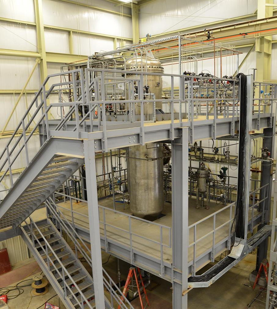

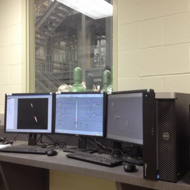
7 Gasification Unit Pictures


 4 Burner CWS gasification")


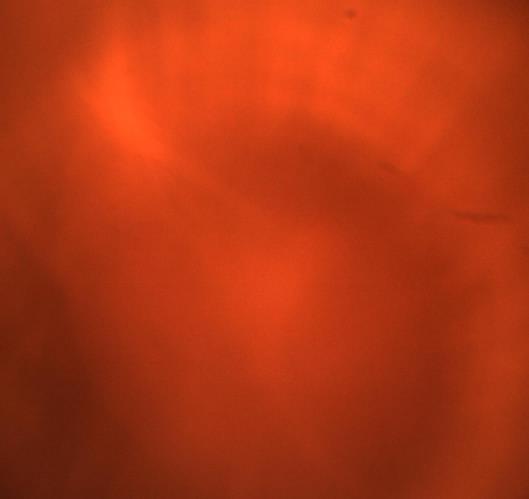
8 Gasification Operation Pictures \ Ignition \ 145 Ignition 145 Ignition 145 Injection of CWS in Burner C, D (Burner A, B with NG on) Ignition of CWS in Burner C, D (Burner A, B with NG on) Shut down 2 Burner CWS gasification (Burner A, B with NG on) 4 Burner CWS gasification (Lens of endoscope fouled) 460 Figure 4 The flame in the gasifier Shut down Figure 4 The flame in the gasifier Gasifier installed and currently being tested Downstream components online soon
 Carbon Capture New Solvents New catalysts New processes and technologies 4.) Gas Conversion by F-T Synthesis Catalysts (Co, Fe, etc.")
9 Future Research Areas 1.) Host site for technology development around CTL Gasification Carbon Capture FT WGS and Refining 2.) Gasification Technology 3.) Carbon Capture New Solvents New catalysts New processes and technologies 4.) Gas Conversion by F-T Synthesis Catalysts (Co, Fe, etc.) Types of F-T reactors Fine tuning based on selectivity of desired product(s) High concentration CWS Increase H/CO ratio and Reduce Downstream Clean-up In-situ WGS with warm sulfur removal Collaboration with Catalyst group, ECUST Coal/Biomass Blending Gasification Research Dynamic Modeling and Controls
10 Carbon Capture Background and Process Description

11 Why CO 2 Capture?

12 CO 2 Capture Possibilities and Utilization Yuan Z., Eden M.R. Industrial &Engineering Chemistry Research Pub date: Nov 30, 2015

")


13 Technology Development Pathway 0.02 MWe (0.1 MWth) Lab-scale Unit 0.7 MWe (2 MWth) Pilot-scale Unit MWe Full-scale Unit Proof of Concept Fundamental Thermodynamic and Kinetic Studies MWe Demonstration Unit Concept 1.5 ID Bench-scale Unit Molecular and Process Modeling and Simulations Shengli Power Plant Shandong, China 1.0 M tons/yr US-China Climate Change Working Group MoU Signed July 8, 2014


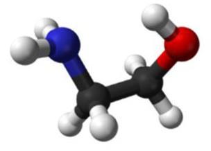
14 CO 2 Capture Chemistry Amine (MEA) + Carbon Dioxide Monoethanolamine (MEA) HEAT
15 Typical CO 2 Capture Flow Diagram Key Equipment: 1) Absorber 2) Stripper 3) Heat Exchangers
16 What Happens in the Absorber? Absorber the equipment that captures CO 2 using a chemical solvent Carbon Rich Stream the chemical solvent after it has absorbed the CO 2 Exothermic chemical absorption Counter current Careful liquid and gas distribution Structured packing
17 What Happens in the Stripper? Stripper the equipment that regenerates the solvent and liberates the captured CO 2 Carbon Lean Stream the chemical solvent after it has been regenerated and contains very little CO 2 Heat is added with the reboiler Reverse the exothermic chemical absorption reaction Structured packing

18 What is Involved in the PGUF Group? Process Modeling and Simulation Chemical Engineering Chemical Process Development Mechanical Engineering Equipment and Structural Design Analytical Chemistry Emissions Studies Solvent Chemical Changes Materials Science Metallurgy Corrosion Studies Energy Efficiency