Sampling Technology for Extractive CEMS & Maintenance Issues of CEMS Sanjeev Rai Perma Pure Aug 9, 2016
|
|
|
- Ethan Murphy
- 5 years ago
- Views:
Transcription


1 Continuous Emission Monitoring System From Understanding to Implementation Sampling Technology for Extractive CEMS & Maintenance Issues of CEMS Sanjeev Rai Perma Pure Aug 9, 2016
2 INDEX Different Application Different CEMS Importance of sampling system Moisture Removal System Real World Experience of Nafion System in India Common CEMS Installation Issues in India CEMS/ CAAQMS Maintenance Issues and measurement accuracy Conclusion


 Trash or other waste (biomass)?")
3 Different Applications Require Different Approaches to CEMS What pollution control systems are now in place? FGD? Wet or dry injection? SCR? What is ammonia slip level? ESP or baghouse? What is particulate level? What is the fuel source? How much sulfur content? (oil, coal) Water % by volume? (8-12% normal) Trash or other waste (biomass)? What is the measurement for? Regulation (CEMS) Process control Perma Pure, 2012 Page 5
4 Why Does Pollution Control Matter for CEMS? 1. Pollution control systems require BEFORE and AFTER measurements for process control and verification. 2. Low-level analytes require more accurate analyzers AND more accurate sample conditioning systems. 3. Key acid gases are highly water soluble. NO 2 and SO 2 HCl and Hf 4. Catalysts and reagents can create unintended consequences with downstream reactions. E.g., Ammonia Injection Perma Pure, 2012 Page 7
5 1. Before and After Measurements BEFORE and AFTER Measurements are essential for verification of system performance. Removal efficiency is often key metric for compliance BEFORE and AFTER Measurements are essential for control of reagent injection (lime, NH 3, trona). Too little reagent = Non-compliance Too much reagent = Wasted expense, reagent handling, downstream waste Perma Pure, 2012 Page 8
6 2. Low-level Analytes SCR with ammonia or urea injection can remove >95% of NO X emissions Dry FGD can remove >90% of SO 2 and HCl emissions For incinerators, lime reacts first with HCl then SO 2 Baghouse provides additional reaction area for dry lime Wet FGD can remove 95% to 98% of SO2 and HCl Measurements for NO X and SO 2 in 2-25 PPM range Daily calibration is a challenge at these levels Perma Pure, 2012 Page 6
7 3. Key Acid Gases are Water- Soluble NO 2 and SO 2 are water soluble, especially as they cool HCl and HF are even more water soluble Traditional CEMS remove water through condensation coolers. Acid gases dissolve in the water and are swept away. Perma Pure, 2012 Page 7
8 SO 2 Solubility in Water SO 2 Solubility (cc SO 2 /100 ml H 2 O) Temperature (Deg. C) Perma Pure, 2012 Page 8
9 Importance of Sampling System Gas Sample Conditioning Systems is an integral part of the Analyser System. Analyser is as good as it s Sample. Tighter emission norms means more accurate measurement. It is legendary within the analyzer community that sampling causes 80% of the process analyser downtime( Clevett, K.J Process Analyser Technology.New York: Wiley Science) Analyser reliability have improved substantially but the system reliability has not improved much because the sampling system are still the same

10 ANALYSER SYSTEM
11 Gas Cooling Characteristic Gas cools down from 300 deg C to 30 Deg C in about 120 mm of bare tubing 1 Gas cools down from 300 deg C to 30 Deg C in about 500 mm of insulated tubing 1 Only way to avoid condensation is to have heated sample line which are properly terminated and do not have cold spots 1 Gross and Bundschuh
12 Moisture Removal Systems Condensor Condensers cool the gas below the dew point, and then remove the condensed liquid water from the gas stream. Water removal is performed automatically to prevent filling the condensate trap and flooding the sampling line. Permeation Dryer Permeation dryers are constructed using Nafion, a material that selectively allows the mass transfer of water vapor from the sample gas through the tube membrane to dry purge gas flowing in an outer tube in the opposite direction.


13 About Nafion Nafion is a copolymer of Teflon and Sulfonic acid and is highly resistant to chemical attack while selectively permeating water through the membrane. Nafion removes water by absorption as water-of-hydration. Because this is a specific chemical reaction with water, the process is very selective and gases being dried or processed are usually entirely unaffected. The transfer of moisture is driven by the differential water vapor pressure between the membrane sides
14 Nafion Permeation Dryers Selectivity Totally Retained by Nafion Atmospheric Gases Halogens Hydrocarbons Inorganic Acids Other Organics Oxides Sulfur Toxic Gases Ar He H 2 N 2 O 2 O 3 Br 2 Cl 2 F 2 I 2 Simple forms (alkanes) HCl HF HNO 3 H 2 SO 4 Aromatics Esters Ethers CO CO 2 SO X NO X COS H 2 S Mercaptans COCl 2 HCN NOCl Typical Combustion Analytes


15 Nafion Dryer Construction 1. Tube and shell design 2. Sample is passed through Nafion tube 3. Dry purge gas is passed through Shell 4. The dry Purge gas sweeps away the moisture through Nafion tube. 5. The sample gas is dried while the purge gas is humidified
16 Advantages of Nafion In the Nafion based sample conditioning system the moisture is removed in vapor phase which results in minimum pollutant gas loss due to condensation Final Dew point after the Nafion system can be as low as 25 Deg C which reduces the chance of acid mist formation. Can be mounted directly on the stack thus reducing the electric load requirement. Stack Mounting Reduces Maintenance and cost No moving parts Lower Downtime of Analyser Figure
17 Real World Experience of Nafion System in India


18 Nafion System in India


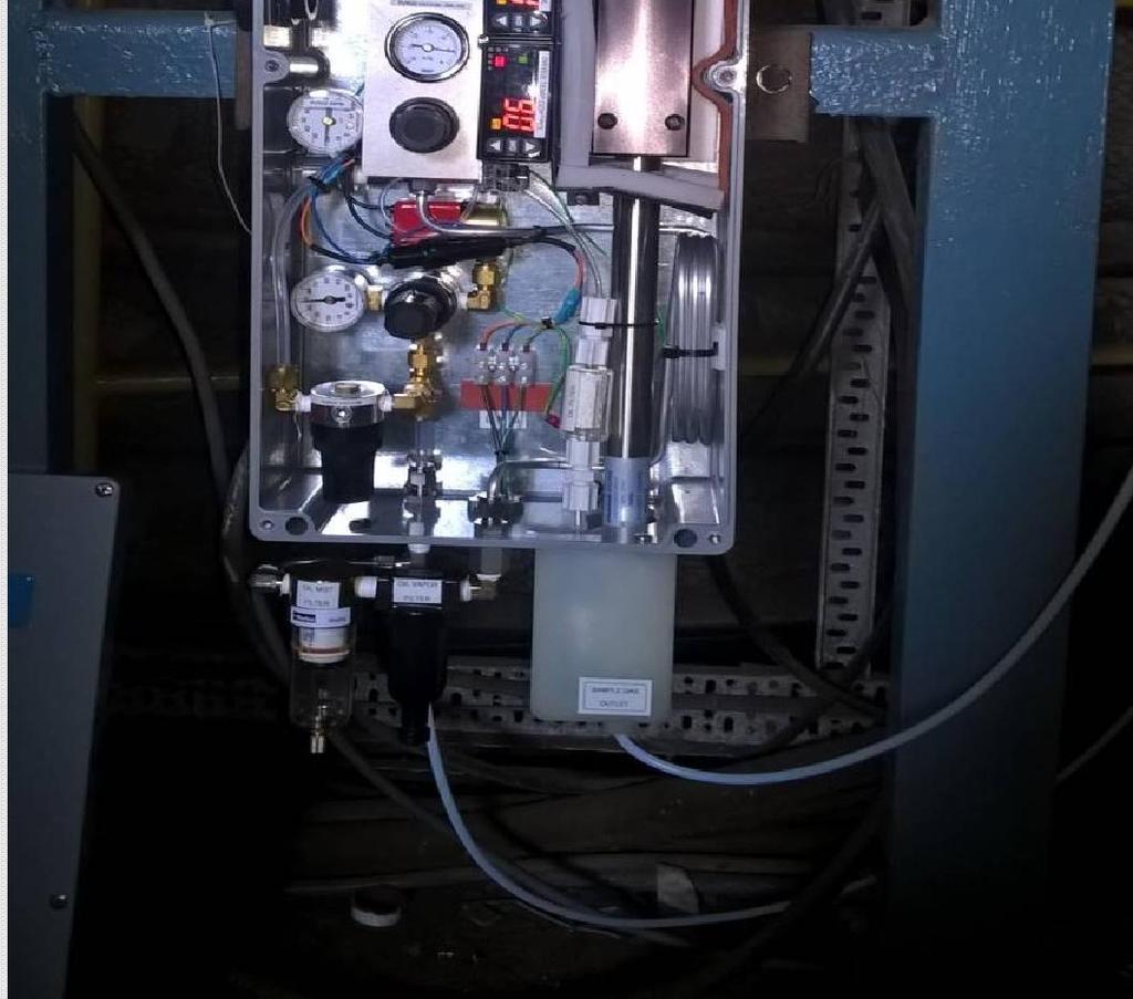
19 Nafion Systemin India
 was")

 Reading in Analyzer was as follows : NOTE")
20 Analyzer Reading Before Installation of Nafion System Sample Dew Point (After Sample Cooler & Before Readi-Gass Installation) was : >25 (>30-40%) COULD NOT USE TESTO 605H1 as we found High amount of moisture coming out from Sample Pump Outlet which can be easily seen & can feel by hand. SOX,NOX,CO & H2O (ppm) Reading in Analyzer was as follows : NOTE : Moisture (H20) inside Sample : 4949 PPM


")
21 Analyzer Reading & Sample Dew Pt. After Installation Nafion System (Along with Sample Cooler) NOTE : After Installation of Read-GASS Sample Dew Pt. comes to -1.2 and Analyzer showing 2526 PPM H2O (WITH SAMPLE COOLER INLINE)


22 Analyzer Reading & Sample Dew Pt. After Installation Readi-GASS (WITHOUT Sample Cooler) NOTE : After Installation of Read-GASS Sample Dew Pt. comes to -8.2 and Analyzer showing 1007 PPM H2O (WITHOUT SAMPLE COOLER)


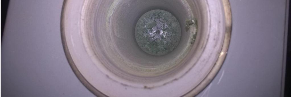
23 Result of Power failure at Probe


24 Installation at SCR in China Power Plant for control application Pre SCR installation
25 COMMON CEMS INSTALLATION ISSUES IN INDIA


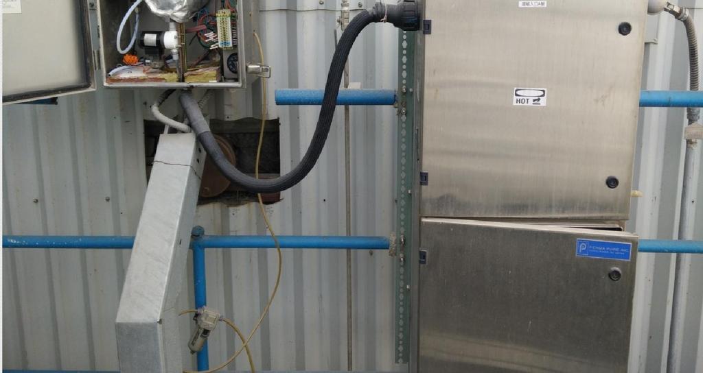
26 CEMS Installation in India HEATED PROBE BUT NO HEATED LINE BETWEEN PSHS AND PROBE


27 CEMS Installation in India HEATED SAMPLE LINE HEATED PROBE BUT NEVER POWERED ON SINCE INSTALLATION ( 5 YEARS OLD INSTALLATION)


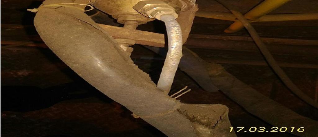
28 CEMS Installation in India HEATED PROBE HEATED LINE BUT NOT PROPERLY TERMINATED


29 CEMS Installation in India HEATED PROBE HEATED LINE BUT NOT PROPERLY TERMINATED


30 CEMS Installation in India HEATED PROBE HEATED SAMPLE LINE BUT NORMAL LINE INSIDE ANALYSER CABINET


31 CEMS Installation in India CONDENSATION IN THE SAMPLE LINE INSDE ANALYSER ABINET


32 CEMS Installation in India No Heated Sample Line upto the cooler


33 CEMS Installation in India Perisaltic pump was regularly failing so they iremoved pump and installed autodrain system


34 CEMS Installation in India NO HEATED SAMPLE LINE BEFORE NAFION DRYER
35 GAS ANALYSER SYSTEM CEMS MAINTENANCE ISSUES & MEASURMENT ACCURACY PRESENTED BY GG SALES AND SERVICES
36 GAS ANALYSER SYSTEM (MAINTENACE ISSUES) MOST OF THE INSTALLATION USE EITHER EXTRACTIVE TYPE OR INSITU TYPE ANALYSER SYSTEMS Both these systems have their pros and cons In both these systems we use optical principle for detecting the gases like CO/CO2/NOx/SOx Both these systems need calibration Above all both these systems need regular maintenance for functioning and providing accurate measurement
37 GAS ANALYSER SYSTEM (MAINTENANCE ISSUES) INSITU SYSTEMS The first and foremost issue here is the alignment Since they are mounted directly at stack, we often face issues due to vibration. If not properly installed, they pose a permanent problem. Often results in drifts, sub zero readings (-ve), which is practically impossible
38 GAS ANALYSER SYSTEM (MAINTENCE ISSUES) To prevent the optical path getting dirty, most manufacturers employ purging of the insitu probes This purging is done through instrument air or with blowers Here we face issues like poor instrument air quality & blower pre filters blockages, Purge hoses getting damaged resulting in reduced purge pressure
39 GAS ANALYSER SYSTEM (INSITU SYSTEMS MEASURMENT ACCURACY) How to ensure measurement accuracy Proper fixing of Insitu probe Ensuring quality purge air / pressure Periodical calibration as recommended by OEM or one can devise their own calibration cycle depending on equipment performance Cross checking with standard equipment
40 GAS ANALYSER SYSTEM (MAINTENANCE ISSUES) EXTRACTIVE SYSTEMS OVERVIEW In the extractive systems, we have 3 to 4 stages First stage is Sample extraction, which will be done using probes/with pre-filters/blow back arrangement Second Stage is sample transportation, which includes Heated sample tubes / pumps to transfer the sample from tapping point to analyzer room The third stage is sample conditioning, here we try to dry the gas using gas coolers, filters, flow regulators and then feed it to analyzers The last stage here is analysis using various analyzers
41 GAS ANALYSER SYSTEM (MAINTENANCE ISSUES-EXTRACTIVE SYSTEMS) The first and foremost job here is proper design engineering and implementation Maintenance issues arises in any of the four stages mentioned earlier. Most of the time, the issue with any sample gas conditioning is to get dry samples. We employ Heat traced sample lines between probe and Analyzer room, but when it enters the analyzer shelter, we often bring the unheated hose inside the cabinet/shelter. With Panel /Shelter AC, there will be a sudden drop in temperature and condensation occurs, resulting in gas cooler over loading and sample loss.
42 GAS ANALYSER SYSTEM (MAINTENANCE ISSUES EXTRACTIVE SYSTEMS) Any condensation in the gas cooler will be removed by automatic drains/peristaltic pumps. Most of the time they get overloaded due to improper insulation issues and condensation during transportation. In case of any failure in cooler/any moisture present in the sample after cooler will be detected by a moisture sensor. The control electronics associated with the moisture sensor will generate an alarm. As this alarm is interconnected to sample pump, it trips and there by stopping the complete system. In most of the site, this interlock will be bypassed as it stops the pump which means no sample Proper positioning of gas cooler and pump in the system
43 GAS ANALYSER SYSTEM (MAINTENANCE ISSUES EXTRACTIVE SYSTEMS) Any condensation in the gas cooler will be removed by automatic drains/peristaltic pumps. Most of the time they get overloaded due to improper insulation issues and condensation during transportation. In case of any failure in cooler/any moisture present in the sample after cooler will be detected by a moisture sensor. The control electronics associated with the moisture sensor will generate an alarm. As this alarm is interconnected to sample pump, it trips and there by stopping the complete system. In most of the site, this interlock will be bypassed as it stops the pump which means no sample
44 GAS ANALYSER SYSTEM (MAINTENANCE ISSUES EXTRACTIVE SYSTEMS) Another issue observed is that in most cases, we only do re-active maintenance than pro-active maintenance One needs to chalk out a PM schedule which includes daily visual checks /replacement of consumables on regular basis(as prescribed by OEM) Never bypass any of the sample conditioning units Improper selection of materials often results in corrosion and which in turn results in leakages Leakages cause false readings often we get high O2 values and lower values for all other components Some time wrong calibration may also cause false readings
45 GAS ANALYSER SYSTEM (MAINTENANCE ISSUES EXTRACTIVE SYSTEMS) Some of the common issues here are Mal functioning of Heat traced tubing Mal functioning of Gas cooler Mal functioning of Sample gas pump Condensation of sample Dust or corrosive soot entering the analyzer All the above issues causes false readings


46 Portable Sample Conditioning System for Onsite Testing
47 Conclusion How to ensure measurement accuracy Installing insulated Heat traced tubing with temperature controller Going for latest sample handling technology like installing Membrane gas driers (Nafion) directly at Stack Using Membrane driers before analyzer inlet Chalking out a preventive maintenance schedule and calibration schedule
48 Conclusion CEMS is a system and not merely an instrument, if any component of system is not installed as per the best practice the accuracy will get compromised. As permitted levels of Sox and NOx are continually being reduced, it is even important to consider right conditioning technology to get representative sample. During inspection it is important to look the complete system from probe to analyzer.
49 Thank You Sanjeev Rai Guru Mahadevan Mobile: