Wedging Angle Effect on the Aerodynamic Structure of a Rutland 913 Horizontal Axis Wind Turbine
|
|
|
- Shona Patterson
- 5 years ago
- Views:
Transcription
1 International Journal of Fluid Mechanics & Thermal Sciences 2016; 2(1): doi: /j.ijfmts ISSN: (Print); ISSN: (Online) Wedging Angle Effect on the Aerodynamic Structure of a Rutland 913 Horizontal Axis Wind Turbine Zied Driss *, Slah Driss, Walid Triki, Mohamed Salah Abid National Engineering School of Sfax (ENIS), Laboratory of Electro-Mechanic Systems (LASEM), University of Sfax, Sfax, Tunisia address: zied.driss@enis.rnu.tn (Z. Driss) *Corresponding author To cite this article: Zied Driss, Slah Driss, Walid Triki, Mohamed Salah Abid. Wedging Angle Effect on the Aerodynamic Structure of a Rutland 913 Horizontal Axis Wind Turbine. International Journal of Fluid Mechanics & Thermal Sciences. Vol. 2, No. 1, 2016, pp doi: /j.ijfmts Received: April 12, 2016; Accepted: April 18, 2016; Published: July 5, 2016 Abstract: Numerical simulation was achieved to study the aerodynamic characteristics around horizontal axis wind turbine of Rutland 913 type. Our study has been focus on the wedging angle effect. From application of the commercial computational fluid dynamics code "Fluent", the distribution of the velocity fields and static pressure was presented in different planes of the considered control volume. These results present the local characteristics of the turbulent flow and give us informations about the wind turbine performance. Indeed, the geometrical parameters have been compared to choose the optimal conditions of the wind turbine. Keywords: CFD, Modeling, Wedging Angle, Rutland Introduction Wind energy is the fastest growing source of energy. Subsidy programs were required, to stimulate the installation of such a large wind energy capacity. As such, there is still a lot of work needed to develop the technology, so that it is cost competitive with conventional sources. For example, Hu [1] developed an experimental investigation on the properties of the near wake behind the rotor of a horizontal-axis wind turbine at model scale. Measurements were made with a stationary slanted hot-wire anemometer using the technique of phase-locked averaging. The primary aim is to study the formation and development of the three-dimensional wake. Five axial locations were chosen within four chord lengths of the blades over a range of tip speed ratios. The results show that during the downstream development of the wake, the wake centre traces a helical curve with its rotation direction opposite to that of the rotor. Grant et al. [2] described a wind-tunnel study of the wake dynamics of an operational, horizontal-axis wind turbine. The behavior of the vorticity trailing from the turbine blade tips and the effect of was interference on wake development were considered. Laser sheet visualisation (LSV) techniques were used to measure the trajectories of the trailing vorticity under various conditions of turbine yaw and blade azimuth. Selected results obtained in the experimental study were compared with the predictions of a prescribed wake model and are being used in the further development of the method. Barnsley and Wellicome [3] made surface pressure and near rotor velocity measurements, using a laser Doppler facility, at six radial positions for a 1 m diameter two-bladed rotor, over the stalling range of tip speed ratios at typical Reynolds' numbers of Velocity measurements have been used to quantify local incidence and results illustrate clearly the development of enhanced lift incidence due to a delay in the loss of leading edge suction peaks compared to 2D behavior. Static hysteresis in the stall behavior has also been identified. Power comparisons with full scale data indicate fairly good agreement in peak power coefficient and tip speed ratio at the onset of stall but also show significant Reynolds number effects in the stalling and post stall regions. Ting et al. [4] developed wind chiller in CCT Lab. Directly uses wind force to drive refrigeration system and hence reduces two times energy conversions between mechanical and electrical


.")
2 2 Zied Driss et al.: Wedging Angle Effect on the Aerodynamic Structure of a Rutland 913 Horizontal Axis Wind Turbine energies. The wind chiller needs high wind speed for its effective work due to the large working torque is required by the compressor. For the purpose of enlarging the applied wind field by the wind machine, this work aims to develop a dual system of wind chiller integrated with wind generator. The integrated wind generator can use the wind energy which cannot effectively drive the compressor. Therefore, the new developed dual system can apply larger range of the wind field and further increase the total working efficiency of the wind machine. Chen and Liou [5] quantitatively investigated the effects of tunnel blockage on the turbine power coefficient in wind tunnel tests of small horizontal-axis wind turbines. The blockage factor was determined by measuring the tunnel velocities with and without rotors using a pitot-static tube under various test conditions. Results showed that the BF depends strongly on the rotor tip speed ratio, the blade pitch angle, and the tunnel blockage ratio (BR). This study also showed that the blockage correction is less than 5% for a BR of 10%, which confirms that no blockage correction for a BR less than 10% in literatures is acceptable. Driss et al. [6] studied the effect of the Rutland 913 wind turbine airfoils. The numerical results obtained in the cases of the airfoils type SD2030 and BM4640 are particularly predicted and analyzed. Driss and Abid [7] studied the aerodynamic characteristics on an open circuit tunnel. They are interested to verify that the test vein provides a uniform out flow, a high-speed and a low-turbulence. The comparison between the numerical results and the global experimental results, conducted within a hot wire anemometry AM-4204 model, confirms the validity of the numerical method. On the basis of the previous studies, it appears that there is paucity on the study of the blade wedging angles effect. For thus, a numerical investigation is presented in this paper to study the geometrical parameters on the aerodynamic characteristics of a horizontal axis wind turbine of Rutland 913 type. Figure 1. Control volume. 2. Geometrical Parameters The considered wind turbine, called Rutland 913, is a six-blade horizontal-axis with a SD2030 airfoil type. This turbine is equipped by a scoop to increase the output power (Figure 1). So, energy capture can be improved at lower wind speeds [8-10]. In this paper, different wedging angles, equals to β=5, β=10, β=15 and β=20, were considered (Figure 2). The results are presented using a cylindrical coordinate system (r, θ, z) with the origin in the centre of the wind turbine. The orientation of the z-axis coincides with symmetrical axis of the scoop and the considered control volume. (b) Wedging angle 10


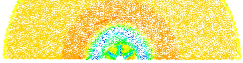
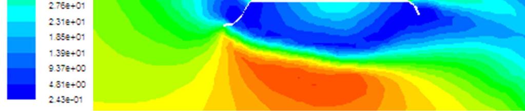
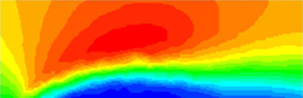
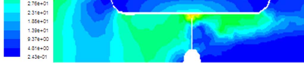
3 International Journal of Fluid Mechanics & Thermal Sciences (1): 1-9 (c) Wedging angle 15 (d) Wedging angle 20 plane defined by the axial position z=0 m. According to these results, it is clear that the flow is uniform and presents a horizontal direction in the inlet of the control volume. While approaching to the wind turbine equipped by the scoop, the velocity field is affected by the geometric configuration. In fact, a flow deceleration appears on the entry, the exit and around the external envelope of the scoop. However, inside the scoop the flow takes back his movement in the wind turbine upstream. At the end of the turbine wind blades, an acceleration of the flow is appeared. This fact is also observed far from this domain and particularly it is generated from the scoop collector. Otherwise, it has been noted that the wedging angle have an effect on the velocity vectors distribution. The recirculation zones appear more large around the scoop and in the wind turbine downstream with a wedging angle equal to β=20. The maximal value of the velocity in the proximity of blade decreases with the increase of the wedging angle. In fact, the maximal value of the velocity is equal to V=33.3 m.s-1 with a wedging angle β=5. However, it is equal to V=27.5 m.s-1 with a wedging angle β=20. This fact proves that it is important to consider the wedging angle β=5 to increase the velocity value and improve the wind turbine performance. Figure 2. Considered wedging angles. 3. Numerical Results The numerical results were conducted within the commercial computational fluid dynamics code "Fluent". The Navier-Stokes equations are solved by a finite volume discretization method. The turbulence model used is the RNG k-ε [11-14]. The distribution of the velocity fields and the static pressure was presented in different planes of the considered control volume to study the wedging angle effect of the Rutland 913 wind turbine Velocity Fields Figures 3, 4 and 5 compare the velocity fields around the Rutland 913 wind turbine equipped by a scoop for different wedging angles equals to β=5, β=10, β=15 and β=20. These results are presented in the longitudinal planes defined by the angular positions θ=0 and θ=30 and the transverse 3


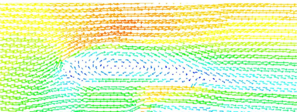
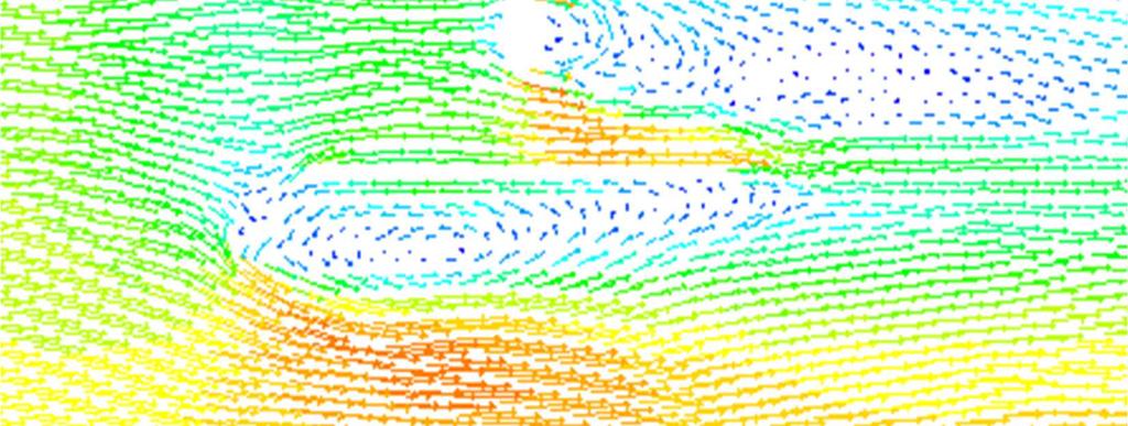


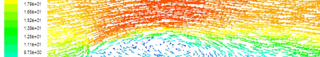
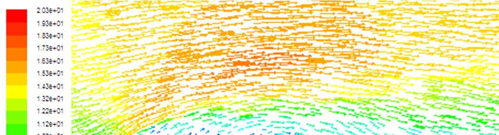

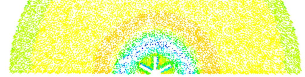

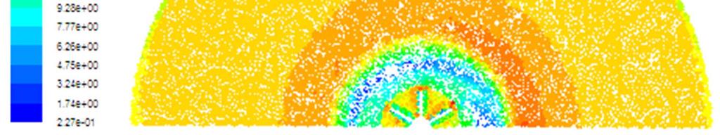
4 4 Zied Driss et al.: Wedging Angle Effect on the Aerodynamic Structure of a Rutland 913 Horizontal Axis Wind Turbine Figure 4. Velocity fields in the longitudinal plane defined by the angular position θ=30. Figure 3. Velocity fields in the longitudinal plane defined by the angular position θ=0.

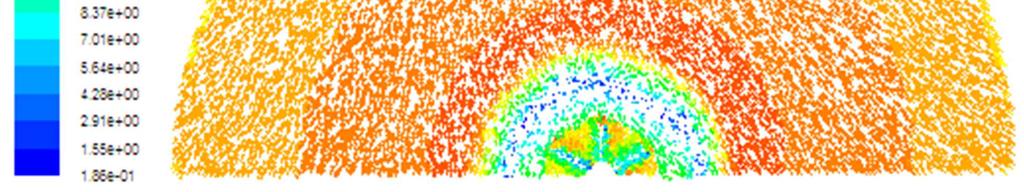


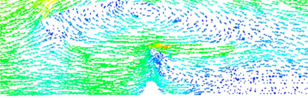
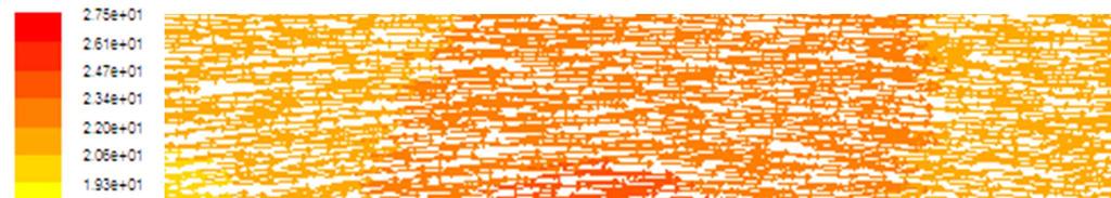
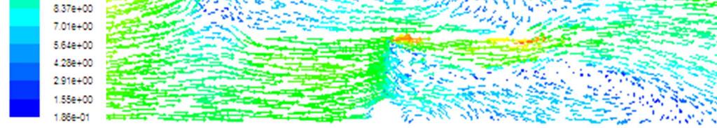
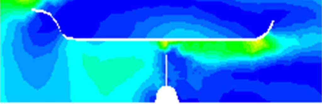
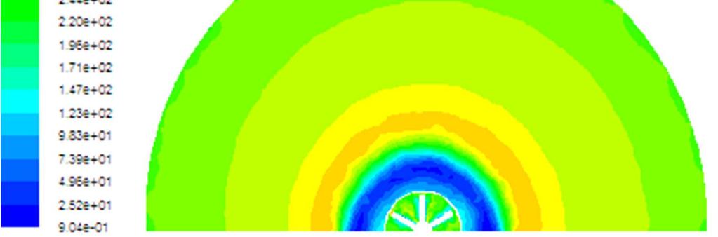
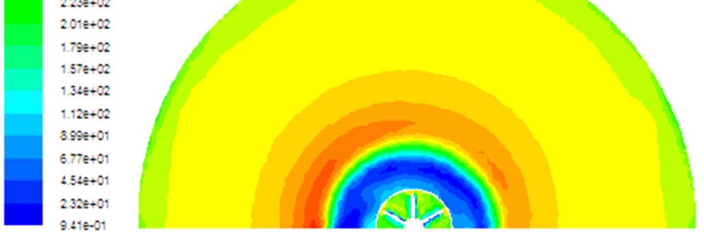
5 International Journal of Fluid Mechanics & Thermal Sciences (1): Figure 5. Velocity fields in the transverse plane defined by the axial position z=0. Figure 6. Distribution of the static pressure in the longitudinal plane defined by the angular position θ=0.


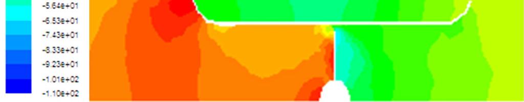


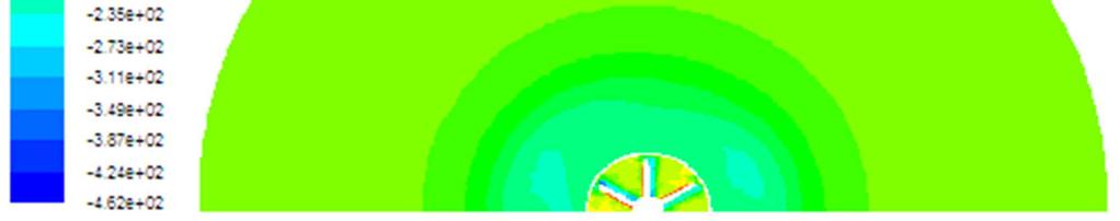

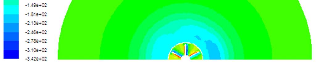


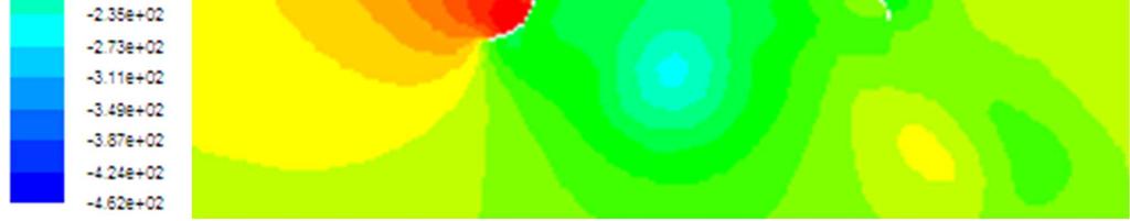
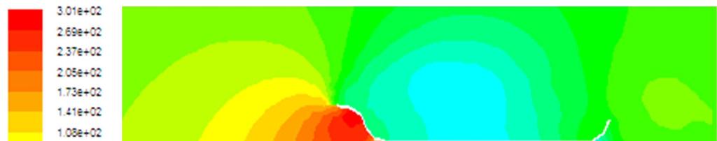
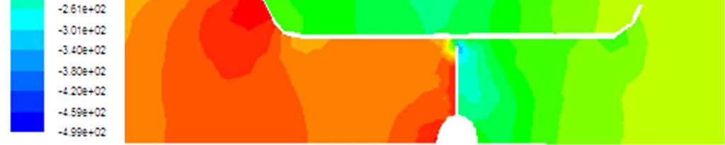
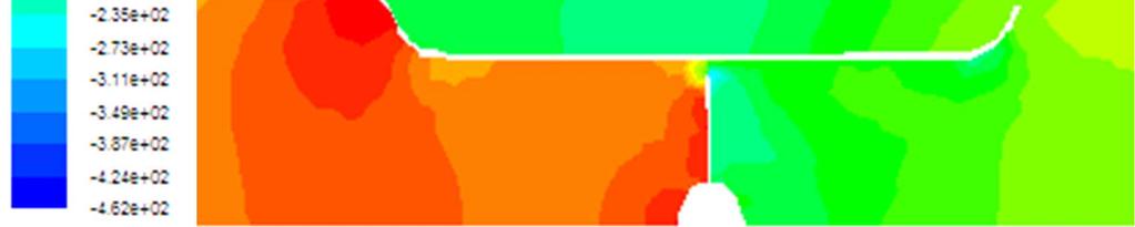
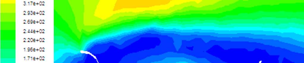
6 6 Zied Driss et al.: Wedging Angle Effect on the Aerodynamic Structure of a Rutland 913 Horizontal Axis Wind Turbine Figure 7. Distribution of the static pressure in the longitudinal plane defined by the angular position θ=30. Figure 8. Distribution of the static pressure in the transverse plane defined by the axial position z=0 m.


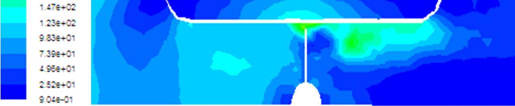

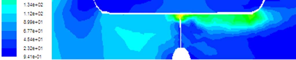

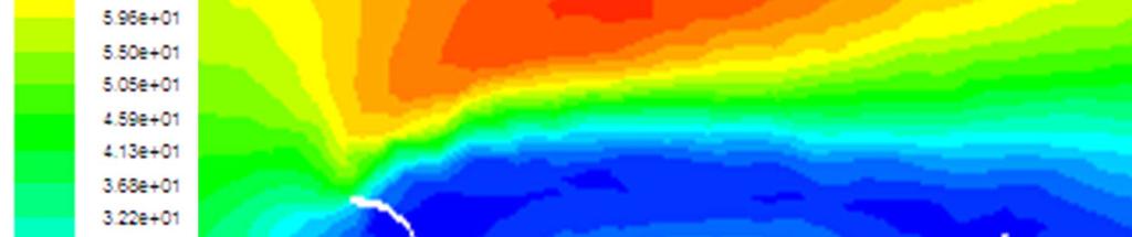
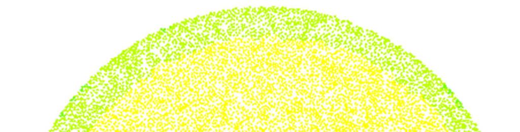
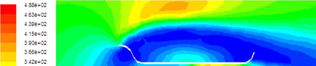
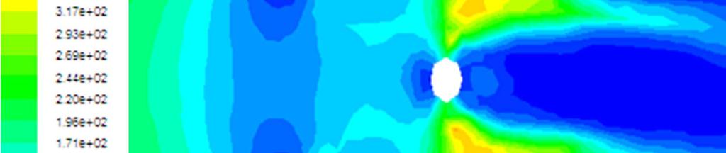
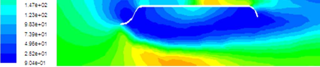
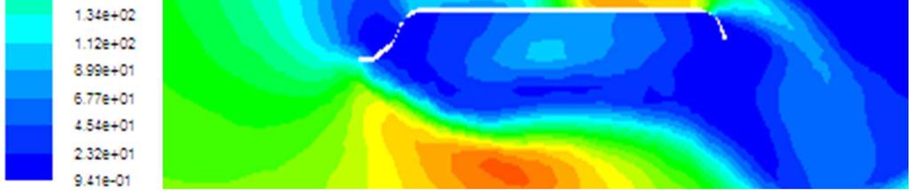
7 International Journal of Fluid Mechanics & Thermal Sciences (1): Figure 9. Distribution of the dynamic pressure in the longitudinal plane defined by the angular position θ=0. Figure 10. Distribution of the dynamic pressure in the longitudinal plane defined by the angular position θ=0.


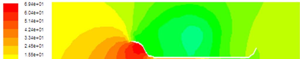
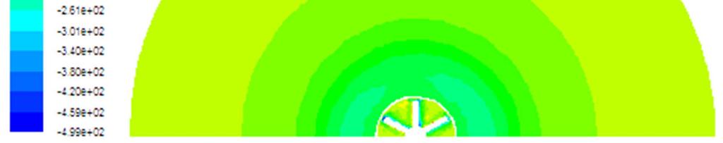
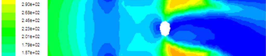
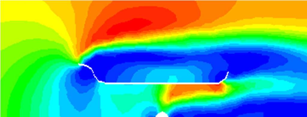
8 8 Zied Driss et al.: Wedging Angle Effect on the Aerodynamic Structure of a Rutland 913 Horizontal Axis Wind Turbine exit and around the external envelope of the scoop. The first depression zone takes root in the scoop collector by merging his surface from the two sides. In the scoop inside, the dynamic pressure increases with the airflow advancement. While approaching to the wind turbine, the dynamic pressure decreases again. The same fact has observed in the turbine wind downstream where the depression zone is developed more and more. In the scoop outside, this wake crosses the one coming from the scoop collector. Otherwise, the compression zones characteristics of the maximum values of the dynamic pressure are created in the scoop inside and more precisely in the downstream blades. In the scoop outside, others compression zones are developed and generated from the scoop collector. While comparing these results relative to the different wedging angles, it is clear that the maximum value of the dynamic pressure decreases with the increase of the wedging angle. In fact, the maximal value of the dynamic pressure is equal to p d =488 Pa with a wedging angle β=5. However, it is equal to p d =91.5 Pa with a wedging angle β= Conclusion Figure 11. Velocity fields in the transverse plane defined by the axial position z= Static Pressure Figures 6, 7 and 8 compare the distribution of the static pressure for different wedging angles equals to β=5, β=10, β=15 and β=20. These results are presented in the longitudinal planes defined by the angular positions θ=0 and θ=30 and the transverse plane defined by the axial position z=0 m. According to these results, it is clear that the static pressure presents a compression zone on the upstream of the scoop and the wind turbine. The maximal values are obtained in the scoop inside the collector neighborhood and just at the level of the wind turbine. However, the depression zones are localized around the external envelope of the scoop and in the wind turbine downstream inside the scoop. While comparing these results relative to the different wedging angles, it has been noted that the maximal value of the static pressure is obtained with β= Dynamic Pressure Figures 9, 10 and 11 compare the distribution of the dynamic pressure for different wedging angles equals to β=5, β=10, β=15 and β=20. These results are presented in the longitudinal planes defined by the angular positions θ=0 and θ=30 and the transverse plane defined by the axial position z=0 m. According to these results, it is clear that the depression zones characteristics of the weakest values of the dynamic pressure are created on the entry, the In this paper, the aerodynamic characteristics around a Rutland 913 wind turbine with different wedging angles have been studied. Particularly, we have compared the numerical results obtained from the application of the commercial CFD code "Fluent". From the numerical results, it has been noted that the wedging angle has a direct effect on the recirculation zones shape which are less developed with β=5. The compression and depression zones shape are widely assigned by the wedging angle value. The weakest value of the static pressure is obtained with β=5. In the future, we propose to develop an experimental investigation within a particle images velocimetry laser (PIV) system. References [1] Hu, D., 2009, Near wake of a model horizontal-axis wind turbine, Journal of Hydrodynamics, 21 (2), [2] Grant, I., Mo, M., Pan, X., Parkin, P., Powell, J., Reinecke, H., Shuang, K., Coton, F., Lee, D., 2000, An experimental and numerical study of the vortex laments in the wake of an operational, horizontal-axis, wind turbine, Journal of Wind Engineering and Industrial Aerodynamics, 85, [3] Barnsley, M. J., Wellicome, J. F., 1992, Wind tunnel investigation of stall aerodynamics for a 1.0 m horizontal axis rotor, Journal of Wind Engineering and Industrial Aerodynamics, 39, [4] Ting, C. C., Lai, C. W., Huang, C. B., 2011, Developing the dual system of wind chiller integrated with wind generator, Applied Energy, 88, [5] Chen, T. Y., Liou, L. R., 2011, Blockage corrections in wind tunnel tests of small horizontal-axis wind turbines, Experimental Thermal and Fluid Science, 35,
9 International Journal of Fluid Mechanics & Thermal Sciences (1): [6] Driss, Z., Triki, W., Abid, M. S., 2011, Numerical investigation of the Rutland 913 wind turbine airfoils effect on the aerodynamic structure flow, Science Academy Transactions on Renewable Energy Systems Engineering and Technology, 1 (4), [7] Driss, Z., Abid, M. S., 2012, Numerical and experimental study of an open circuit tunnel: aerodynamic characteristics, Science Academy Transactions on Renewable Energy Systems Engineering and Technology, 2 (1), [8] Wang, F., Bai, L., Fletcher, J., Whiteford, J., Cullen, D., 2008, The methodology for aerodynamic study on a small domestic wind turbine with scoop, Journal of Wind Engineering and Industrial Aerodynamics, 96, [9] Wang, F., Bai, L., Fletcher, J., Whiteford, J., Cullen, D., 2008, Development of small domestic wind turbine with scoop and prediction of its annual power output, Renewable Energy, 33, [11] Driss, Z., Abid, M. S., 2012, Use of the Navier-Stokes Equations to Study of the Flow Generated by Turbines Impellers, Chapter 3, Navier-Stokes Equations: Properties, Description and Applications, [12] Driss, Z., Ammar, M., Chtourou, W., Abid, M. S., 2011, CFD Modelling of Stirred Tanks, Chapter 5, Engineering Applications of Computational Fluid Dynamics, Vol. 1, [13] Driss, Z., Bouzgarrou, G., Chtourou, W., Kchaou, H., Abid, M.S., 2010, Computational studies of the pitched blade turbines design effect on the stirred tank flow characteristics, European Journal of Mechanics B/Fluids, 29, [14] Ammar, M., Chtourou, W., Driss, Z., Abid, M.S., 2011, Numerical investigation of turbulent flow generated in baffled stirred vessels equipped with three different turbines in one and two-stage system, Energy, 36 (8), [10] Driss, Z., Triki, W., Abid, M. S., 2011, Caractérisation aérodynamique des éoliennes à axe horizontal équipées de rotors sphérique et elliptique, Récents Progrès en Génie des Procédés, 101, 1-6.