Lecture 11. WATER PUMPING EQUIPMENT and DEWATERING SYSTEM
|
|
|
- Tobias Arnold
- 5 years ago
- Views:
Transcription


1 Lecture 11 WATER PUMPING EQUIPMENT and DEWATERING SYSTEM TSP-308 MPK Ferdinand Fassa
")
2 dewatering The purpose is to remove water from an excavation without causing instability in either the side slopes or the bottom Improve excavating and hauling Increase stability of excavated slopes Reduce lateral loads on bracing Prevent rupture of the bottom of the excavation Dewatering methods: open pumping pre-drainage cutoff and exclusion ground freezing (freezewall) combination 2
3 Factors affecting the selection of dewatering method Nature of soil Groundwater hydrology Size and depth of excavation Proposed method of excavation and ground support Proximity of existing structures; type and depth of foundations Design and function for structure being built Schedule Nature of any contamination at the site 3
4 side effects of dewatering Settlement of adjacent area Temporary reduction in yield of water supply wells in adjacent area Long-term damage to water supply aquifer due to salt water infiltration Aerobic organism attack to timber structure below water table Lower water table harms vegetation 4
5 principle of fluid flow D arcy s law of flow: Q = K.A.h/L Q = quantity of water flow K = permeability of medium (soil) A = cross sectional area h/l = friction loss in distance L (hydraulic gradient) 5
6 Piezometer Applications Monitoring dewatering schemes for excavations and underground openings. Monitoring ground improvement techniques such as vertical drains, sand drains, and dynamic compaction. Monitoring pore pressures to determine safe rates of fill or excavation. Investigating the stability of natural and cut slopes. Monitoring the performance of earthfill dams and embankments. Monitoring seepage and ground water movement in embankments. Monitoring pore pressures to check containment systems at landfills and tailings dams. 6

7 Types of Piezometer Standpipe Pneumatic Vibrating wire Multi level Vented 7
8 terminologies of dewatering Aquifer zone of soil or rock through which groundwater moves Confined aquifer permeable zone between two aquicludes Aquicludes layers of clay or rock that is essentially impervious to water flow Transmissibility (T) the easiness of water moves through a unit width of aquifer T = K.B (gpd/ft or m 2 /day) 8
9 Range of Permeability of Natural Soil Description Permeability (µ/sec) Openwork gravel GP 10,000 or higher Uniform gravel GP 2,000 10,000 Well graded gravel GW 500 3,000 Uniform sand SP 50 2,000 Well graded sand SW 10 1,000 Silty sand SM Clayey sand SC 1 10 Silt ML Clay CL

10 Water pumps The main function is to move liquid material from one (undesirable) location to another (desirable) locations Benefits and Applications of Water Pumps in Construction Projects To remove water from undesirable location to another locations To dry up construction site To provide water when and where needed Facilitate grouting process Water pumps are important pieces of equipment for wet construction, such as rivers, swamps, and when raining 10

11 example of pumping system 11

12 Application of Pumping System Waste-water Plant Sewage pump station Storage of wastewater Intake lift station Homogenisation sludge storage Recirculation of digested slurry Pumping returnactivated sludge Biological treatment process Equalisation tank 12

13 Mining Active dewatering Open cast drainage Recovery of slurry Recovery of water Face & stage dewatering Shaft bottom drainage Main drainage station Nuisance liquid/slurry handling 13

14 Industry Mixing of drilling mud Handling of mill scale process water Handling of bottom ash Mixing in quenching tank Waste water pump station White water handling Coal pile run-off sump Raw water intake 14

15 Construction Temporary by-pass pumping Manhole clean-up & drainage Tunnelling drainage Work site drainage Flood defense & clean-up Seawater drainage Active dewatering Stand-by pumps 15
16 Construction pumps frequently perform under severe conditions: Dewatering cofferdams Removing water from pits, tunnels and other excavations Lowering the water table for excavations Furnishing water for jetting 16
17 Factors affecting the selection of Pumping Types Capability and capacity of pumping system Types and amount of attachments (fitting, pipes, valves, etc.) Height of pumping Reliability of pumping system and equipment Easiness of operation (including number of operators) Easiness of maintenance and repair Economic values 17


18 Types of Pumping Equipment DISPLACEMENT PUMPS Reciprocating Diaphragm reciprocating centrifuge CENTRIFUGAL PUMPS Principle: kinetic to potential energy conversion 18

19 Rotary Displacement Pumps 19

20 Reciprocating Pumps inflow single acting inflow outflow double acting outflow outflow 20
21 Reciprocating Pumps Advantage Able to deliver constant rate at various elevation Efficient (small head loss) Self priming High speed and large capacity Disadvantage Valves are potential to damage, especially for pumping water with abrasive material Potential damage for pumping at high head Bulky and heavy Unsteady flow 21
22 Reciprocating Pumps Pumping Capacity Q 2 d l n c 924 N c = loss of efficiency due to slippage ( ) d = diameter of cylinder (inch) l = length of stroke (inch) n = number of strokes / minute (x 2 for double acting) N = number cylinders in a single pump (N = 2 for duplex) Pumping Power P W 33,000 w Q h 33,000 e W = energy to move water (ft-lbs/minute) w = weight of 1 gallon of water/liquid (lbs) Q = pump capacity (gpm) h = total head (including loss) (ft) e = pumping efficiency (%) 22
23 Pumping Power Water horse power (WHP) is the power required to accomplish pump a volume of water over a total dynamic head (TDH) WHP TDH( ft ) Q( 3960 gpm ) WHP TDH( m ) Q(l 4569 / min) Break horse power (BHP) is the amount of power that must be applied to the pump. BHP Efficiency is the ratio of WHP over BHP TDH( ft ) Q( 3960 e gpm ) e WHP BHP 23
24 24


25 Diaphragm Pumps Good for pumping dirty water or water that contains soil particles Good for pumping in large capacity Pumping capacity two-inch, single : 2,000 gpm three-inch, single: 3,000 gpm four-inch, single : 6,000 gpm four-inch, double : 9,000 gpm 25
26 Centrifugal Pumps Rotation element (impeller) produces a velocity that causes liquid to discharge against considerable pressure. Kinetic energy (velocity) is converted to potential energy (height) Pumping efficiency up to 75% Self-priming Submersible pump Multi-stages pump (for suction and discharge) V 2gh 2 V 2g V = velocity (fps) g = gravity acceleration (fps) 32.2 sea level h = height of fall (feet) h 26

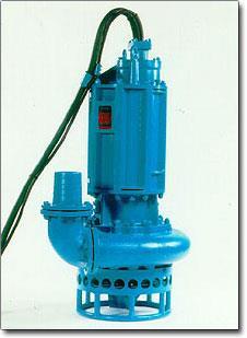
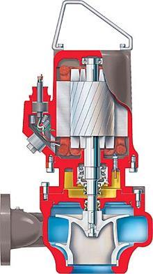
27 Submersible Pumps 27

28 Installation of Submersible Pumping System 28
29 29
30 Pressure Loss in Piping System Water flow inside piping system will loose its pressure (flow energy) due to: Friction against pipe surface Dimension and Geometric of pipe Difference in elevation (head) Tables for Pump capacity Equivalent length of pipe for various fittings & valves Friction loss per 100 ft of steel pipes Friction loss per 100 ft of hose h = 2.31 p or p = h h p = difference in elevation (head), ft = pressure at, psi 30
31 Pressure loss in piping system total static head static discharge head total suction lift Total static head is the static suction lift plus the static discharge head C L discharge Static discharge head is the vertical distance from the pump impeller to the point of discharge impeller C L Static suction lift is the vertical distance from the pump impeller to the surface of the liquid pumped. Suction capability is limited by atmospheric pressure. Maximum practical suction lift is 25 ft. Decreasing suction lift will increase the volume that can be pumped. 31
32 Effect of Altitude and Temperature Above 3,000 ft there is a definite effect on pump performance. A self-priming pump will lose about one foot of priming ability for every 1,000 ft of elevation. At an elevation of 7,000 ft, a self-priming pump will only develop 18 ft of suction lift. As the temperature of water increases suction lift will decrease. At sea level practical suction lift is: 0 o F = 25.0 ft. 100 o F = 15.5 ft. 32
33 forces to move water A pump works against heads (restraining forces) h t = h l + h f + (h v or h p ) + h 0 h t = total dynamic head h l = static suction lift h f = total friction head h v = velocity outlet h p = pressure outlet h 0 = elevation difference h v = v 2 /2g (ft) v = velocity h p = p/w (ft) p (psf) & w (pcf) 33
34 Water friction and velocity head in 1000 ft of smooth bore hoses Size (inch) Head Water Flow (gpm) h t h v h t h v h t h v h t h t
35 Head Loss Friction of water per 100 ft of plastic pipes 35

36 Head Loss 36
37 Head Loss Friction of water per 100 ft or 100 m of steel pipes 37
38 Head Loss Friction of water per 100 ft or 100 m of steel pipes 38
39 Head Loss Friction of water per 100 ft or 100 m of hose 39
40 Head Loss Friction of water per 100 ft or 100 m of hose 40
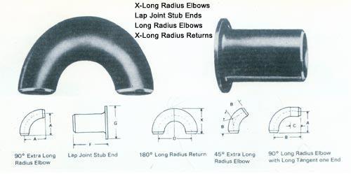
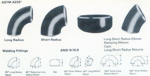
41 Piping Accessories 41


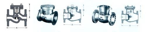
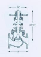
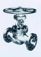
42 Valves Check Valves Diaphragm Valves Gate Valves Globe Valves 42
43 Head Loss Equivalent length of steel pipe of fittings and valves (ft) Item Nominal size (inch) 1 1-1/4 1-1/ / o elbow o elbow Tee, side outlet Close return bend Gate valve Globe valve Check valve Foot valve


44 Capacity of M rate Self Priming Centrifugal Pumps 44

45 Capacity of M rate Self Priming Centrifugal Pumps 45
46 WELL-POINT SYSTEM original water table depressed water table depressed water area 46

47 Well-point System Are used to lower water table to provide a water-free construction site environment Are used in ground material that is homogeneous such as sands and silts. Good to pulling water down to approximately 18 (6m) below original water table Staging will allow deeper dewatering but requires more space 47
48 Q WELL-POINT SYSTEM R o original water table Q 2 K B H R ln o rw h w B r w h w H Q = pumping quantity (gpm) K = permeability (fps) H = depth of original water table (ft) h w = depth of depressed water table (ft) R o = radius of depressed area (ft) r w = radius of riser pipes (ft) B = thickness of confined aquifer (ft) 48
49 Multistage Well-point System original water table Depressed water table 49

50 Multistage Well-point System raiser raiser raiser spacing 2 5 ft header 50


51 Well-point Dewatering System Main Pump Header pipes Raiser pipes 51

52 Well-point Dewatering System Things to consider Physical layout Adjacent areas Soil conditions Permeability The amount of water to be pumped Depth of imperviousness Stratifications 52
")
53 Other well system Borewell system Large diameter Water supply Horizontal well system Oil and gas industry Concentric Dewatering System Vacuum wellpoints (for fine-grained soils) 53

54 DEEP WELLS Large-diameter deep wells are suitable for lowering the water table when the soil becomes more pervious with depth or the excavation penetrates or is underlain by sand or coarse granular soils. 54
55 SURFACE PUMPING METHODS Sumps and Ditches: A perimeter ditch, inside the excavation, carries seep water to a sump. The sump is located in the deepest part of the excavation. Water collected in the sump is pumped away. ditch sump 55
56 Exercise Design water pump system to discharge water from a ditch to a temporary water storage, given the following technical specifications: Required capacity 700 gpm Total pipe length 320 ft Depth of pipe suction below water 12 ft Height of pump above water 9 ft Height of water discharge above pump 35 ft Piping accessories: 2 gate valves 4 90 o elbows 1 45 o elbow 1 check valve 1 foot valve 56
57 Terima Kasih Reference: CONSTRUCTION DEWATERING New Methods and Applications, 2 nd Ed. J. Patrick Powers 57