AVALON AT SOUTH BAY PROJECT
|
|
|
- Jasmin Reynolds
- 5 years ago
- Views:
Transcription
 Carson, California April 17, 2008 Prepared by: TETRA")

1 AVALON AT SOUTH BAY PROJECT Deep Dynamic Compaction Work Plan For Avalon at South Bay (Formerly Carson Marketplace) Carson, California April 17, 2008 Prepared by: TETRA TECH 348 W. Hospitality Lane, Suite 100 San Bernardino, California Prepared for: Carson Marketplace, LLC 4350 Von Karman Avenue, Suite 200 Newport Beach, California 92657
2 DEEP DYNAMIC COMPACTION WORK PLAN FOR AVALON AT SOUTH BAY (FORMER CAL COMPACT LANDFILL) MAIN STREET CARSON, CA Prepared for: Carson Marketplace, LLC 4350 Von Karman Avenue, Suite 200 Newport Beach, CA Prepared by: TETRA TECH, INC. 348 West Hospitality Lane, Suite 100 San Bernardino, CA April 17, 2008
3 Avalon at South Bay Deep Dynamic Compaction Work Plan April 17, 2008 Section TABLE OF CONTENTS Page SECTION 1.0 INTRODUCTION SITE DESCRIPTION AND SCOPE OBJECTIVE SITE BACKGROUND... 3 SECTION 2.0 DESIGN CRITERIA... 4 SECTION 3.0 DDC OBJECTIVE AND APPROACH... 6 SECTION 4.0 PILOT TEST SITE PREPARATION SIZE AND LOCATION OF TEST SECTION AVERAGE GROUND LOSS CRATER DEPTH INFORMATION TEMPERATURE AND METHANE READINGS SUBSURFACE EXPLORATION PILOT TEST SUMMARY REPORT SECTION 5.0 SCHEDULE SECTION 6.0 MONITORING SECTION 7.0 EMISSIONS CONTROL SECTION 8.0 REFERENCES List of Figures Figure 1 Figure 2 Figure 3 Figure 4 Figure 5 Site Map Vicinity Map Development Plan DDC Areas DDC Grid Pattern List of Appendices Appendix A Woodward-Clyde. Deep Dynamic Compaction Test Data Report LA Metro Mall, Carson, California (Excluding Appendices) Tetra Tech. Inc. i
4 Avalon at South Bay Deep Dynamic Compaction Work Plan April 17, 2008 SECTION 1.0 INTRODUCTION This Deep Dynamic Compaction (DDC) Work Plan (Work Plan) applies to the Avalon at South Bay development project (Site), which was previously named Carson Marketplace. This proposed brownsfield restoration project involves the development of the former Cal Compact landfill into multiple land uses, including commercial, entertainment, retail stores, restaurants, hotels, and residential. This Work Plan describes the activities to implement a DDC Program for the Project site. The test measurements from the proposed pilot test program will be used to confirm any modifications to the DDC design to ensure the most efficient method is implemented to dynamically compact the existing trash. 1.1 Site Description and Scope Carson Marketplace, LLC (Developer) has proposed to develop the Avalon at South Bay development project (Project). The Project site comprises approximately 168 acres of land located at Main Street in Carson, California. The main property (157 acres) is bounded on the east/northeast by the San Diego Freeway (I-405), on the north by Del Amo Boulevard, on the west by Main Street and single family residences and mobile home development, and on the south by single family residences and mobile home development (Figure 1). A strip of vacant land to the north across Del Amo Boulevard, which comprises 11 acres, is also within the overall scope of the Project. This portion of the property was not part of the former landfill and the development activities planned for it are, therefore, not included in the provisions of this Work Plan. The former Cal Compact landfill consists of five separate landfill cells numbered A1 through A5 separated by the site boundaries on the outer perimeter and by two interior roadways on the interior perimeter (Lenardo Drive and Stamps Drive). A Los Angeles County Flood Control channel (Torrance Lateral) is located adjacent to the south and west sides of the Project site and serves to separate the Project site from the adjacent residential neighborhood (Figure 2). This Project involves the development of the former Cal Compact landfill into the following land uses: neighborhood commercial, regional commercial, commercial entertainment, big-box retail stores, restaurants, hotels, and residential (Figure 3). The construction phases of this Project will begin with mass grading of the former landfill area and relocation of some of the soil covering the landfill cells. This will be done to establish a uniform grade and minimize the thickness of suitable soil cover overlying the refuse material so that compaction of the landfill cells may commence. Soil removed in the grading process will be temporarily stockpiled onsite until it is reused for subsequent backfill. Compaction of refuse will be done using DDC to consolidate the refuse and soil below future parking and open areas to reduce future differential settling. The trash under future building locations will not be compacted. Once all compaction is complete, a landfill gas collection system with horizontal collection wells throughout the site and vertical gas collection wells below future building locations will be installed. This gas collection system will be connected to a gas flare treatment system located in a landfill operations center which will have controls and integral monitoring to detect any leakage or system failure. The landfill cells and gas collection system will then have a multi-component landfill cap installed. The first layer of this cap will be the installation of a continuous layer of linear low density polyethylene Tetra Tech, Inc. 1
5 Avalon at South Bay Deep Dynamic Compaction Work Plan April 17, 2008 (LLDPE) geomembrane which will serve as the primary impermeable layer of the cap system. This LLDPE geomembrane will then have drainage strips installed on top of it that will direct water off of the landfill cap so that it does not accumulate. These drainage strips will be covered by a geotextile fabric layer to resist the accumulation of silt and clogging of the drainage system. This layer will then be covered with soil. All future buildings will be supported on driven piles. Piles will be driven through the refuse until competent native soil is reached. Pile caps will be installed and the concrete building slabs will be poured on top. The LLDPE geomembrane will be sealed to the pile caps where they penetrate it using an expansion boot to allow expansion and movement while remaining sealed. A building protection system will be installed below all building locations to serve as a backup in case of landfill cap or primary gas collection system failure. This system will include the installation of a membrane attached to the underside of the concrete slab. The space between this membrane and the LLDPE geomembrane will have a passive gas venting system installed and will also include methane detection sensors to provide notification of any accumulation of methane under the building slabs. All buildings will be built aboveground. The Project will also include the installation of a groundwater extraction and treatment system along the southern boundary of the Project site to contain and treat impacted groundwater. Some refuse materials in the landfill cells may need to be excavated and moved to facilitate the installation of site utilities and the landfill gas collection system. Tetra Tech is the environmental engineer and general contractor responsible for the design and installation of these remedial systems. Tetra Tech is not, however, responsible for the design and installation of the driven piles, pile caps, and building slabs that make up the building foundations. 1.2 Objective The purpose of DDC is to densify the upper portion of the landfill trash and provide a more stable base for the landfill cap geomembrane and any improvements in the areas under planned parking and road (open) areas. This will assist in minimizing differential settlement in the open areas and promote better surface water drainage over the long term. In addition, DDC will assist in lowering the existing elevations in the open areas by several feet with out having to remove the protective soil cover or remove and relocate any on-site trash. Lowering the elevation of the open areas during DDC will allow for a balanced site and minimize the need to import or export soil. Following DDC, the rough grade will be established. The landfill subsurface conditions have been evaluated in various reports prepared in the mid- 1990s and in Specifically, a DDC pilot test was conducted in 1995 (Woodward-Clyde 1995) and is included in Appendix A (without appendices) in this Work Plan for reference. While the landfill operations were terminated in 1964, relatively little data are available about the amount and rate of settlement that has occurred since termination of the landfill operations. Further settlement and differential settlement are anticipated; the extent of each has been estimated as best possible (Leighton 2008). Tetra Tech, Inc. 2
6 Avalon at South Bay Deep Dynamic Compaction Work Plan April 17, Site Background Land use of the property prior to landfill operations was primarily agricultural, including grazing, dairy, feedlot, and cropland (Brown & Root 1995a). Prior to the 1930s, the land immediately surrounding the property was also used primarily for agriculture, with some limited residential development. During the 1940s, industry was introduced to the area and residential areas also became more extensive. The current light industry, commercial, and residential mix of surrounding land uses was fully developed by the 1970s (Brown & Root 1995a). Between 1959 and 1964, the property was used as a Class II landfill and is currently covered by a layer of soil that varies from 4 to 32 feet in thickness (Arcadis BBL 2008). According to Los Angeles County records, Cal Compact, Inc. (Cal Compact), a California corporation, was issued an industrial waste disposal permit on July 17, 1959, which authorized Cal Compact to operate a Class II landfill on the property (Brown & Root 1995b). Landfill operations began on this property in April 1959 and continued until 1964, prior to the site closing in February The landfill operations consisted of the placement and cover of wastes in excavated trenches. All wastes were placed in trenches that were excavated adjacent to the interior haul roads. The haul road locations have remained unchanged throughout the time the landfill was in operation and are underlain by native soil materials (Brown & Root 1995b). The landfill was permitted to accept both municipal solid waste and specified industrial liquid wastes. During the life of the landfill, approximately 6 million cubic yards of solid municipal waste and 6.3 million gallons of industrial liquid waste were received at the landfill (Brown & Root 1995c). Available records indicate that over 90 percent of the liquid wastes were drilling fluids that consisted primarily of water and clay mixtures, with minor heavy metal additives and oily residue. Other wastes received included solvents, oils, sludges, heavy metals, paint sludges, and inorganic salts. On March 18, 1988, Remediation Action Order Number HSA87/ was issued, requiring investigation of contamination at the landfill site and preparation of a remedial action plan (RAP). A RAP was prepared and approved by the Department of Toxic Substances Control (DTSC) in The objective is to develop the Project for mixed uses that benefit the surrounding community. At the same time, the RAP will be implemented to protect human health and the environment during construction and after the Project development is complete and operating. Tetra Tech, Inc. 3
7 Avalon at South Bay Deep Dynamic Compaction Work Plan April 17, 2008 SECTION 2.0 DESIGN CRITERIA The 1995 DDC pilot test was used as the general basis of design for this Work Plan, with some adjustments. The previous pilot test made the following observations and recommendations that were utilized in the DDC design and approach described in this Work Plan. 1. An average 5-foot layer of soil cover above the trash was recommended. Therefore, DDC preparation on the site will be done on 3 to 5-acre sub areas. Soil will be relocated in these areas to achieve around 4 to 6 feet of soil above trash before DDC activities begin. 2. A grid spacing of 15 and 20 feet were used during the pilot test with a 27 ton weight at a height of 100 feet (Woodward-Clyde 1995 Table 5). With 5 drops per grid point, this equates to 67.5 to 120 ton-feet/square-foot (tf/sf), about a 90 tf/sf average. 3. The highest efficiency (90 percent) of crater development and trash compression (with no intermediate backfill) occurred with 5 drops (27 tons at a 100-foot drop). More drops started to produce heave and a significant drop in efficiency. 4. The majority of penetration and compaction occurred with the first 5 drops. Penetration was 0.5-foot or less per drop after this (Woodward-Clyde 1995 Figure 10). The first two drops generally developed over 60 percent of the crater depth in the 5 drop tests. The average crater depth after five drops ranged from 4 to 7 feet in the two pilot test areas. The pilot test did include DDC with up to 10 drops per location, but required intermediate backfill of the craters after 5 drops. 5. An Ironing Phase of 2 drops at a height of 30 feet was adequate for compacting the soil around the primary DDC area after the 100-foot drops were conducted. 6. Dust, vibration and noise monitoring during the DDC operations indicated no significant issues. Based Tetra Tech s analysis of the 1995 DDC pilot test results, Tetra Tech has modified the DDC design criteria as follows. 1. Recommendation 1 above is unchanged. 2. Recommendation 2 above is changed to a 14-foot grid with a 26-ton weight and a drop height of 95 feet. This will apply a minimum of 85 tf/sf during the High Energy phase of the DDC, which is estimated to be sufficient to achieve the objective of the DDC work. 3. With respect to Recommendations 3 and 4 above, a reduction of elevation of up to 5-feet will be targeted using approximately 6 to 8 drops at 95 feet as described below in Section 3.0. Backfilling will occur after the High Energy phase, unless intermediate backfilling is required before all of the High Energy Phase drops are completed to help control emissions from the craters based on on-site monitoring. Tetra Tech, Inc. 4
8 Avalon at South Bay Deep Dynamic Compaction Work Plan April 17, The Ironing Phase in Recommendation 5 is adjusted from a drop height of 30 feet to 25 feet, based on consultation with DDC experts and vendors that this height will likely be sufficient to smooth the surface sufficiently for subsequent grading activities. Backfilling and compaction of the craters may be conducted by alternate means to assist in maintaining the schedule. 5. Recommendation 6 above is unchanged. Tetra Tech, Inc. 5
9 Avalon at South Bay Deep Dynamic Compaction Work Plan April 17, 2008 SECTION 3.0 DDC OBJECTIVE AND APPROACH DDC will be performed on approximately 61 acres of the site, as shown on the attached Figure 4. These areas are where parking and new roads are planned over the existing trash. DDC operations will apply a certain amount of energy to the trash and overlying soils and will compress and consolidate these materials such that future differential settlement will be reduced. Per the 1995 pilot test and the DDC scope in the Design Construct Environmental Assurance Agreement, the minimum amount of energy to be applied during DDC operations is 85 ton-feet per square foot (tf/sf). It is anticipated that the project geotechnical engineer will randomly check DDC operations to confirm that the minimum amount of energy is applied. The DDC monitor will be selected and/or provided by the City of Carson or the Developer. In addition, records of all DDC activities will be provided on a monthly basis for review by the City of Carson. The soil stockpile areas where excess soil will be temporarily stored as a result of any DDC preparation required is shown on Figure 4. These stockpiles will ultimately be the source of soil used in the backfilling of the craters and for achieving the rough liner grade. DDC will be performed in two phases. The first, High Energy Phase, is designed to achieve the proposed compaction. The second phase, the Ironing Phase, is intended to smooth the landfill surface in preparation for the installation of the LLDPE geomembrane at the liner grade. Areas along the existing main roads that are on native soil material will be evaluated to determine if DDC should be applied up to the edge of the road, based on proximity of the edge of landfill waste to the road. In addition and to the extent practicable, DDC will be completed such that it overlaps approximately five feet under where future building pads will be constructed in the future. The anticipated earth moving and DDC procedures are described below. 1. A land surveyor will initially stake the corners of the building slabs and parking areas prior to the commencement of preparation for DDC. 2. Prior to the start of the High Energy Phase of DDC, excavation will occur, where necessary, to reduce the landfill soil cover to approximately 4 to 6 feet in thickness. Excavated soil cover material will be stockpiled in non-ddc areas for eventual filling of craters created by DDC, for ground leveling, or for establishing the rough grade. DDC preparation activities are described in the Soil Management Plan (Tetra Tech 2008a). 3. Following site preparation as described in Item 1 and 2 above, the High Energy Phase of DDC will be undertaken in two steps, both using a 26-ton tamper with a 95-foot drop. The goal of the High Energy Phase is to apply a cumulative average energy of least 85 tf/sf over the areas shown in Figure 4. The first step of the High Energy Phase will consist of approximately 4 to 6 drops at the primary pass locations (see Figure 5). Each DDC location will be observed for possible exposure of trash during DDC activities. The drop points will be spaced about 14 feet apart on a square grid Tetra Tech, Inc. 6
10 Avalon at South Bay Deep Dynamic Compaction Work Plan April 17, 2008 pattern. Wherever the High Energy Phase creates a crater that exceeds 6 feet in depth before the anticipated numbers of drops are applied, the craters may be backfilled with soil to avoid exposing trash and minimize emissions, and then the remaining drops will be applied. If excessive crater depths occur, some of the drops in the first pass of the High Energy Phase may be moved to the second pass. Alternatively, the height of the first drops may be reduced, which might require the number of drops to be increased. 4. The second step (secondary pass) of the High Energy Phase involves the same procedure as described above with approximately 2 drops applied at a 14-foot grid spacing, but at points between the drop locations of the primary pass of the High Energy Phase. 5. After application of the second step of the High Energy Phase as described in Item 4 above, depressions or craters in the soil surface of the 61-acre area will be filled with soil and compacted in order to provide a smooth foundation for the subsequent backfilling or in preparation of the Ironing Phase prior to achieving the grade for the landfill cap geomembrane. 6. After application of the second step of the High Energy Phase as described in Item 4 above and grading in Item 5, a low level energy application called the Ironing Phase may be applied over most of the DDC area in order to prepare a relatively smooth surface for subsequent preparation of the foundation and installation of the geomembrane. The Ironing Phase will consist of 1-2 drops of a 15- to 25-ton tamper from a height of 15' to 25' or the use of a special ironing tamper designed to provide contact pressure at the base of the ironing tamper of approximately 600 to 800 pounds per square foot (psf). Standard forms of compacting the soils in the craters shall also be considered. 7. Surface elevations will be measured in the DDC areas at a grid spacing of 25 to 50 feet center to center before starting the High Energy Phase, before the Ironing Phase, and again after the Ironing Phase. The purpose of the surface elevation measurements is to assist in determining the amount of ground densification as a result of DDC. Periodic inspection and confirmation that the Work Plan objectives are being achieved will be completed by Carson Marketplace s geotechnical engineering firm, Leighton Group. 8. Tetra Tech will perform vibration monitoring during performance of the DDC using an approach that is compliant with Section II, Mitigation Measure H-1 (as applicable), H-2 and H-3 of the Final Environmental Impact Report dated January 2006, including conducting the required Pilot Program before commencement of the actual DDC program. Vibration monitoring will be performed using a Blastmate III or a comparable monitoring system that has the ability to monitor a broad selection of vibration. Vibration monitoring systems will be in accordance with the approved Vibration Monitoring Plan. If unacceptable vibration impacts to nearby residents or others occur, Tetra Tech will respond by 1) reducing the energy applied over an area Tetra Tech, Inc. 7
11 Avalon at South Bay Deep Dynamic Compaction Work Plan April 17, 2008 by decreasing the weight incrementally and/or by using a smaller DDC drop followed by re-monitoring, and/or 2) moving further away from sensitive receptors followed by re-monitoring. As an option, an isolation trench between the DDC operations and the residents may be constructed to reduce vibrations. If this option is selected, the isolation trench will be constructed parallel to the Torrance Channel or streets depending on the soil/trash interface. The trench will be 5-foot wide and up to 8 feet deep. Vibration monitoring during performance of the DDC will be performed in accordance with the Deep Dynamic Compaction Vibration Monitoring Plan, (Tetra Tech 2008b). 9. Tetra Tech will incorporate into its planning documents and field work the requirements associated with complying with the Environmental Impact Report required Mitigation Measures. In addition, Tetra Tech will be responsible for addressing any neighbor complaints, and any nearby structural damages caused by the DDC. Tetra Tech, Inc. 8
12 Avalon at South Bay Deep Dynamic Compaction Work Plan April 17, 2008 SECTION 4.0 PILOT TEST Prior to starting the full-scale DDC, a pilot test will be performed at three pilot test locations (see Figure 4). The test locations are within 500 feet of each other and are positioned near the Torrance lateral, streets, and limits of fill. Simultaneous testing at these locations will demonstrate a worst case scenario for combined conditions (noise, vibration, etc.). It is anticipated that the pilot test will occur for one week. The pilot test objectives are to confirm the most effective procedure for densifying the existing landfill deposits and to confirm that monitoring procedures (vibration, noise, dust, and emissions) are adequate. Field monitoring will include measurement of the depth of crater formation following each series of drops, the average ground loss during and following completion of the High Energy Phase and the Ironing Phase, the amount of ground heave at selected locations, temperature and methane readings for the locations where the craters penetrate into the former landfill, and vibration attenuation measurements. The recommended procedure for the DDC pilot test is presented below. 4.1 Site Preparation Prior to starting the DDC pilot test, the ground surface will be adjusted to leave 4 to 6 feet of existing cap material over the estimated landfill trash interface. This may require excavations to reduce the cap thickness. The ground surface will be shaped to a level surface so that the equipment can travel across the area safely and without problems. 4.2 Size and Location of Test Section Each pilot test section will be approximately 100 feet (ft) x 100 ft (Figure 4). The proposed DDC energy application of 85 tf/sf will be applied over approximately half of this area. This will consist of using a 26-ton tamper with a 95-foot drop. Five drops will be applied at each primary drop point location and 2 drops at the secondary drop point location (Figure 5). The spacing between the drop points will be 14 feet center to center. If the 95-foot drops produce large craters greater than 6 to 7 ft, the other half of the test section area will be densified using lower drop heights, but more drops in order to apply the same unit energy of at least 85 tf/sf. 4.3 Average Ground Loss Prior to DDC, ground surface elevations will be surveyed at points 25-feet center-to-center to establish the existing average ground elevation. After the first phase of the high level energy applied, the ground surface will be leveled with a front end loader or dozer, and then the ground elevation determined at the same survey point locations to determine the average loss in elevation. After the second phase of energy application is applied, the procedure will again be repeated. Finally, after the Ironing Phase, the ground will again be leveled to obtain the final ground loss. Tetra Tech, Inc. 9
13 Avalon at South Bay Deep Dynamic Compaction Work Plan April 17, Crater Depth Information At each location, detailed crater formation information will be obtained. This will include survey measurements taken adjacent to the drop point at distances of 5, 10, and 15 ft beyond the edge of where the tamper will strike the ground. These monitoring points will be established in the northerly, southerly, easterly, and westerly direction from the point at which the tamper strikes the ground. The purpose of this monitoring is to determine the ground heave that occurs following each drop of the tamper. The field procedure will consist of dropping the tamper once at the drop point location and then measuring the depth of the crater penetration. The elevation of the heave measurement points will then be obtained to determine the magnitude of ground heave. After this is completed, a second drop will then be applied and the procedure repeated. This will continue until all 5 drops have been applied. 4.5 Temperature and Methane Readings Methane monitoring will be performed prior to soil cover penetration and/or if trash is exposed. Wherever the tamper penetrates through the soil cover and exposes the underlying trash, readings of ground temperature and methane will be obtained. This information will be helpful in determining the condition of the landfill and the potential for methane gas emissions during the DDC operations. 4.6 Subsurface Exploration Before and after DDC is completed, three borings will be completed in each test section. The borings will be extended through the trash to help determine the relative density of the dynamically compacted trash. Samples and resistance measurements will be obtained at 2.5- foot intervals, nearly continuous, using split-barrel sampling procedures in accordance with ASTM specification D-1586 for a depth of 30 feet below the trash soil interface or to first water, which ever is shallower. As the samplers are removed, temperature readings will be taken of the soil before removal from the split-barrel sampler. For comparison, three borings before DDC will be completed within the test area to determine the standard penetration resistance values of the unimproved landfill deposit. Temperature readings will also be taken on the samples obtained from these borings. 4.7 Pilot Test Summary Report After the pilot test is complete; a geotechnical engineering summary report will be prepared discussing the results of the pilot test measurements and recommend any modifications to the DDC design to achieve the goal of the High Energy Phase of applying a cumulative average energy of least 85 ton-feet per square foot over the anticipated DDC areas. Also, all monitoring activities will be verified to be appropriate, and modifications will be made, as necessary. These evaluations will occur during and immediately after the pilot test and the results will be discuss orally with representative of the City, DTSC, and Carson Marketplace. Based on the Tetra Tech, Inc. 10
14 Avalon at South Bay Deep Dynamic Compaction Work Plan April 17, 2008 results of the oral discussions, DDC will continue. A draft report documenting the results of the pilot test, modifications, and oral agreements will be completed within two weeks following the pilot test. Tetra Tech, Inc. 11
15 Avalon at South Bay Deep Dynamic Compaction Work Plan April 17, 2008 SECTION 5.0 SCHEDULE Three DDC rigs will be used and each rig is estimated to complete 0.25 acres per day. This is equivalent to 125 work days (approximately 5 months) including mobilization and completing the pilot test. Tetra Tech, Inc. 12
16 Avalon at South Bay Deep Dynamic Compaction Work Plan April 17, 2008 SECTION 6.0 MONITORING Monitoring of vibration, noise, and dust will be conducted per the approved Deep Dynamic Compaction Vibration Monitoring Plan (Tetra Tech 2008b), Noise Management Plan (Tetra Tech 2008c), and Fugitive Dust Control Plan (Tetra Tech 2008d). Perimeter and work zone air monitoring will also be conducted per the approved plans (AQMD Rule 1150 Excavation Management Plan [Tetra Tech 2008e] and Air Monitoring Plan [Tetra Tech 2008f]) to ensure local residents and other city occupants are not adversely impacted by the DDC operations. Personnel air monitoring of the DDC workers and observers will also be conducted per the project specific Health and Safety Plan (Tetra Tech 2008g). Tetra Tech, Inc. 13
17 Avalon at South Bay Deep Dynamic Compaction Work Plan April 17, 2008 SECTION 7.0 EMISSIONS CONTROL It is not anticipated that odors, noise, vibration, or elevated concentrations of air emissions (including dust) will create a public nuisance or impact human health or the environment. In the event that the standard provisions and procedures fail, resulting in odors or monitoring data shows that the measured concentration of pollutants exceeds action levels per the AQMD Rule 1150 Excavation Management Plan, excavation or soil disturbing activities will immediately be suspended. Action will be taken to determine the cause of the odor or elevated air emissions. Tetra Tech will implement immediate corrective actions including the application of water or foam on odor or emission sources, covering of exposed refuse with plastic sheets or soil cover, or application of other mitigation measures identified in Section 9 of the AQMD Rule 1150 Excavation Management Plan (Tetra Tech 2008b). Excavation or other soil disturbing activities will not recommence until procedures have been modified or other permanent actions have been taken to correct the problems which resulted in exceedence of the action limits listed in the AQMD Rule 1150 Excavation Management Plan. Once procedural modifications or other permanent actions have been determined and put into place, excavation or other soil disturbing activities may recommence. To ensure that the procedural changes or other corrective actions were effective after the activity has restarted, monitoring must commence immediately. Re-evaluation of the modified procedures and the new monitoring results will determine if the corrective action was effective. The exceedence of the action limit, mitigation measure applied, procedural modifications or other permanent corrective action taken, and the monitoring data from the restart will be recorded on daily construction logs. Additionally, all site personnel will be informed of the procedural changes at daily tailgate safety briefings. Tetra Tech, Inc. 14
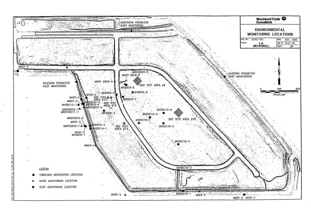
18 Avalon at South Bay Deep Dynamic Compaction Work Plan April 17, 2008 SECTION 8.0 REFERENCES Arcadis BBL Physical Site Characterization Technical Memorandum. January. Brown & Root Environmental 1995a. Final Baseline Risk Assessment for Cal Compact Landfill, Carson, California. August. 1995b. Final Remedial Action Plan, Cal Compact Landfill, Carson, California. October. 1995c. Final Remedial Investigation for Cal Compact Landfill, Carson, California. July. Leighton Consulting, Inc Draft Memorandum: Summary of Settlement Calculations for Refuse Cells at the Tetra Tech, Inc. Proposed Avalon at South Bay Development. February. 2008a. Draft Soil Management Plan. 2008b. Draft Deep Dynamic Compaction Vibration Monitoring Plan, Former Cal Compact Landfill. 2008c. Draft Noise Management Plan. 2008d. Fugitive Dust Control Plan. February. 2008e. Rule 1150 Excavation Management Plan. January. 2008f. Draft Air Monitoring Plan. 2008g. Site Health and Safety Plan. February. Woodward-Clyde Deep Dynamic Compaction Test Data Report LA Metro Mall, Carson, California. Tetra Tech, Inc. 15
19 FIGURES
20 X : \ G I S \ C A R S O N A V A L O N \ V I C I N I T Y. M X D A , , 5 0 V A L O N A T S O U T H B A Y 0 F F e e t J 2 a 0 n 0. 8 i g u r e
21 A R S O A V A L O N z C n e l X :\G IS \C N K \S IT E Ṁ X D D e l A m o B l v d. D o m i n g u e h a n t S. i n M a T o r r a n c e L a t e r a l A V A L O N A T S O U T H B A Y F e e t J a n F i g u r e


22 X:\GIS\CARSON MARKETPLACE\DEV_PLAN.CDR AVALON AT SOUTH BAY Development Plan Development Plan Date: September 17, 2007 Ref. Nadel Jan Figure 3
23 X:\GIS\CARSON-AVALON\DDC AREAS.MXD A1 1 PT-A2 PT-A3 PT-A4 A2 A3 A4 2 3 A5 LEGEND 1 DDC Pilot Test Areas (approx.) DDC Area North Stockpile Area Stockpile area for storage of soil during DDC preparation and building pad grading 2 3 West Stockpile Area Stockpile area for storage of soil not meeting SMGs per Soil Management Plan. Soil to be placed under liner as backfill during DDC operations South Stockpile Area Stockpile area for storage of soil during DDC preparation and building pad grading. This stockpile to be used last as Cell A5 will be graded last SCALE IN FEET 348 W. HOSPITALITY LN. SUITE 100 SAN BERNARDINO, CALIFORNIA (909) TC # DRAWN BY: SH CHECKED BY: APPROVED BY: 02/18/08 AVALON AT SOUTH BAY Figure 4 DDC Areas
24
25 APPENDIX A
26
27
28
29
30
31
32
33
34
35
36
37
38
39
40
41
42
43
44
45
46
47
48
49
50
51

52
53
54
55
56
57
58
59
60
61
62
63
64
65
66
67
68

69
70
71

72

73
74
75
76
77
78
79

80
81
82
83
84
85
86
87
88
89
90
91
92
93
94
95
96
97
98