Shirley E. Clark, Ph.D., P.E. October 5, /30/2012
|
|
|
- Britney Sibyl Alexander
- 5 years ago
- Views:
Transcription


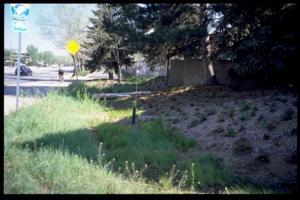
1 Shirley E. Clark, Ph.D., P.E. October 5, 2012 Prior development decisions have led to directly connected impervious areas and pervious areas with heavily-compacted soils. Prince Georges Cty, MD photo 1


2 Urbanization often shortens watershed response times and increases flow volumes and rates 2
3 Goal: Replicate Natural Hydrology Increase infiltration Replenish streamflows Recharge groundwater Increase evapotranspiration Aesthetics Urban heat island effect Designing the Next Generation of Stormwater Practices Technique Techniques for LID Groundwater Recharge Rate (R) or Volume (V) Control Water Quality Pervious Pavement Type of lining? R: Yes V: lining? Yes(?) Infiltration Basin Type of lining? R: Yes V: lining? Yes Infiltration Bed Type of lining? R: Yes V: lining? Yes Infiltration Trench Type of lining? R: Yes V: lining? Yes Rain Garden / Type of lining? R: Yes V: lining? Yes Bioretention Dry Well / Seepage Pit Type of lining? R: Yes V: lining? Yes Constructed Filter Type of lining? R: Yes V: lining? Yes Vegetated Swale Type of lining? R: Yes V: lining? Yes Vegetated Filter Strip Type of lining? R: Yes V: lining? Yes Infiltration Berm Type of lining? R: Yes V: lining? Yes Vegetated Roof No R: Yes? V: Yes Yes? Designing the Next Generation of Stormwater Practices 3
4 Technique Techniques for LID Groundwater Recharge Rate (R) or Volume (V) Control Capture and Re-use?? Yes Yes Constructed Wetlands Yes Yes Yes Water Quality Wet Pond/Retention Basin No R: Yes V: No Yes (?) Dry Extended Detention No R: Yes V: No No Basin Water Quality Filters & No R: Yes? V: No Yes (?) Hydrodynamic Devices Riparian Buffer Restoration No Yes Yes Landscape Restoration / Yes Yes Yes Reforestation Soil Amendment/ Yes Yes Yes (?) Restoration Level spreader No R: Yes V: No No Designing the Next Generation of Stormwater Practices Designing the Next Generation of Stormwater Practices 4

5 Site Design Techniques (PA Manual: Non- Structural Practices) Non-Structural BMP deployment is not a singular, prescriptive design standard but a combination of practices that can result in a variety of environmental and financial benefits. Reliance on Non-Structural BMPs encourages the treatment, infiltration, evaporation, and transpiration of precipitation close to where it falls while helping to maintain a more natural and functional landscape. NS BMP Protect Sensitive / Special Value NS BMP Protect / Conserve / Enhance Riparian Buffers NS BMP Protect / Utilize Natural Drainage Features NS BMP Cluster Uses at Each Site NS BMP Minimize Total Disturbed Area NS BMP Minimize Soil Compaction NS BMP Re-Vegetate / Re-Forest Disturbed Areas (Native Species) NS BMP Street Sweeping / Vacuuming Designing the Next Generation of Stormwater Practices Maintain Time of Concentration Techniques: Open drainage Use green space Flatten slopes Disperse drainage Lengthen flow paths Save headwater areas Vegetative swales Maintain natural flow paths Increase distance from streams Maximize sheet flow Maintaining pre-development time of concentration essential! 5


6 With references to PA Stormwater BMP Manual design criteria What Can Our Storm Distributions Tell Us about Planning? SCS Type II Rainfall Example Central and Western PA are in the SCS Type II Rainfall Design Storm area. 6
7 The Campus Watershed NOTE: Landscape on good soils only makes a contribution during the larger storms. In small, frequent storms, impervious surfaces are biggest contributor of water and pollutants. Technique: Permeable Pavement Allows water to pass through and infiltrate into the ground Austin, Texas parking lot initial infiltration 1,765 in/hr Benefits: Control of TSS and particulate-associated pollutants Concerns: Permeable pavement may not work as well in areas with extreme rainfall amounts, less permeable soils, or dissolved pollutants. Many of these operate as underground detention storage. Permeable and no liners allow for infiltration to either shallow or deep groundwaters. Variety of materials available for permeable pavers. 7


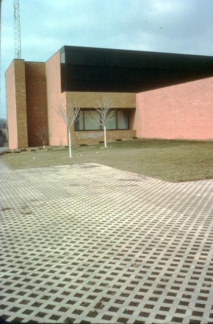
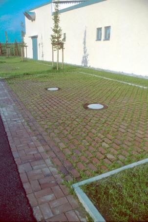
8 Permeable Pavement Porous Paver Blocks 8


9 Technique: Porous Pavement Design PADEP, 2006 Technique: Porous Pavement Design 9

10 Technique: Permeable Pavement Design Equations Volume Reduction Calculations Volume = Depth* (ft) x Area (sf) x Void Space *Depth is the depth of the water stored during a storm event, depending on the drainage area and conveyance to the bed. Infiltration Volume = Bed Bottom Area (sf) x Infiltration design rate (in/hr) x Infiltration period* (hr) x (1/12) *Infiltration Period is the time when bed is receiving runoff and capable of infiltrating at the design rate. No time used in the calculations can exceed 72 hours. (maximum draindown time) Technique: Bioretention Cells/Rain Gardens Layers of sand/soil mixture, rock & vegetation to create area for stormwater to collect and filter through the soil. Infiltration depends on lining (if applicable). Bioretention cells control quantity as well as quality of the stormwater 10


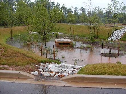
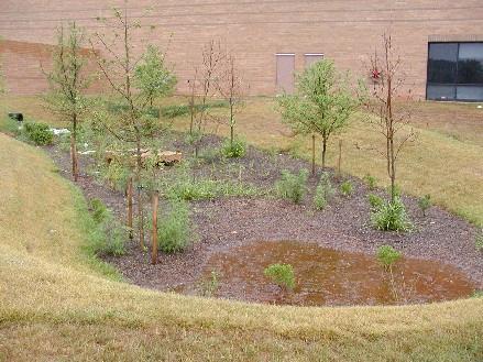
11 Rain Garden Designed for Complete Infiltration of Roof and Parking Lot Runoff 11

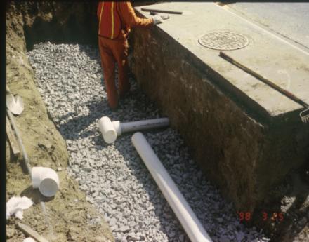
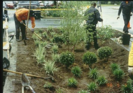
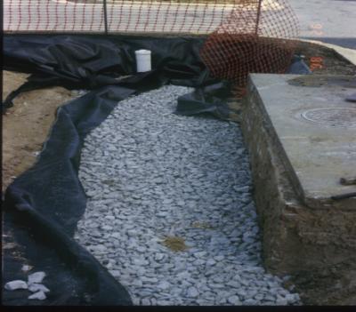
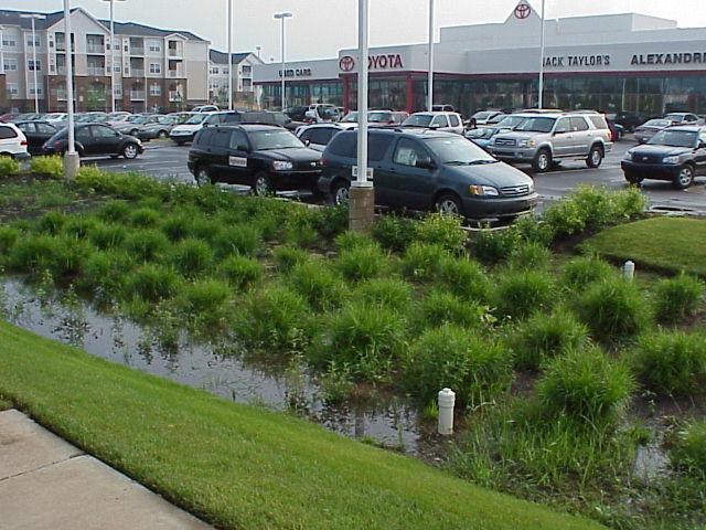
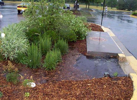
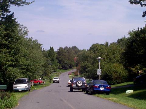
12 Installation of Rain Garden/Bioretention Facility in Parking Lot Rain Garden (in use) in a highly landscaped commercial site along Route

13 PADEP, 2006 Technique: Bioretention Design Guidance Sizing criteria Surface area should generally not exceed a maximum loading ratio of 5:1 (impervious drainage area to infiltration area) Surface Side slopes maximum 3:1 side slopes are recommended, however where space is limited, 2:1 side slopes may be acceptable. Surface Ponding depth should not exceed 6 inches in most cases and should empty within 72 hours. Planting soil depth should generally be at least 18 where only herbaceous plant species will be utilized. Planting Soil should be a loam soil capable of supporting a healthy vegetative cover. A typical organic amended soil is combined with 20-30% organic material (compost), and 70-80% soil base (preferably topsoil). Volume Storage Soils should also have a ph of between 5.5 and 6.5, a clay content less than 10%, be free of toxic substances and unwanted plant material, and have a 5 10% organic matter content. 13

14 Technique: Bioretention Design Guidance Volume Reduction Calculations The storage volume of a Bioretention area is defined as the sum total of (1) and the smaller of (2a) or (2b) below. The surface storage volume should account for at least 50% of the total storage. (1) Surface Storage Volume (CF) = Bed Area (ft2) x Average Design Water Depth (2a) Infiltration Volume = Bed Bottom area (sq ft) x infiltration design rate (in/hr) x infiltration period (hr) x 1/12. (2b) Volume = Bed Bottom area (sq ft) x soil mix bed depth x void space. 14


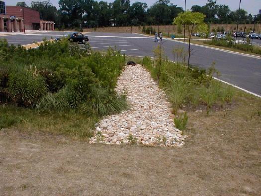
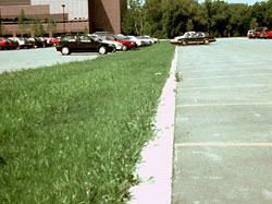
15 Technique: Grass Swales and Filter Strips Grass Swales: Replaces curb & gutter systems Uses grass & other vegetation to redirect high volume flows Reduces runoff velocity May allow runoff to infiltrate into soil Filter Strips Typically placed in parking lots or other large impervious surfaces Collects water for infiltration or for treatment prior to discharge to the traditional storm drainage system. Can direct the water to bio-retention areas Grass Swales Designed to Infiltrate Large Fractions of Runoff 15

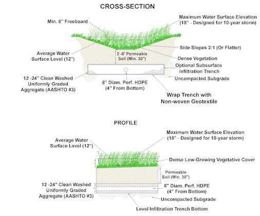
16 Technique: Vegetated Swale Design (per DEP 2006) 16
17 Technique: Design Calculations for Grass Swale Temporarily store and infiltrate the 1-inch storm event Provide conveyance for up to the 10-year storm with freeboard and no erosion of the channel. Maximum ponding depth of 18 inches at the end point of the channel, with a 12-inch average maintained throughout. Six inches of freeboard is recommended for the 10-year storm. Residence times between 5 and 9 minutes are acceptable for swales without check-dams. Maximum ponding time is 48 hours, though 24 hours is more desirable (minimum of 30 minutes). Swale vegetation should not be submerged during design storm or smaller. Longitudinal slopes between 1% and 3%. (for steeper slopes, check dams or TRM s used to reduce energy gradient). Technique: Design Calculations for Grass Swale Check dams also enhance infiltration capacity, decrease runoff volume, rate, and velocity, and promote additional settling of pollutants. Check-dams create a series of small, temporary pools along the length of the swale. Check-dams shall be constructed to a height of 6 to 12 in and be regularly spaced. Siting should aesthetically fit the swale into the landscape. Sharp bends in swales should be avoided. Where possible, construct swales in areas of uncompacted cut. Avoid constructing side slopes in fill material. Soil Testing is required when infiltration is planned (see Appendix C). Swales are typically most effective, when treating an area of 1 to 2 acres although vegetated swales can be used to treat and convey runoff from an area of 5 to 10 acres in size. Runoff can be directed either as concentrated flows or as lateral sheet flow drainage. 17
18 Technique: Design Calculations for Grass Swale Swale soils should be well-drained. If the infiltration capacity is compromised during construction, the first several feet should be removed and replaced with a blend of topsoil and sand. Swales are most efficient when their cross-sections are parabolic or trapezoidal in nature. Swale side slopes are best within a range of 3:1 to 5:1 and should not be greater than 2:1. Bottom widths typically range from 2 to 8 feet. Wider channels require berms or walls to prohibit braiding or uncontrolled sub-channel formation. The maximum bottom width to depth ratio for a trapezoidal swale should be 12:1. Ideal swale vegetation should consist of a dense and diverse selection of close-growing, water-resistant plants whose growing season preferably corresponds to the wet season. Swale vegetation must also be salt tolerant, if winter road maintenance activities are expected to contribute salt/chlorides. Technique: Design Calculations for Grass Swale Check the temporary and permanent stability of the swale using the standards outlined in the Pennsylvania Erosion and Sediment Pollution Control Program Manual. Swales should convey either 2.75 cfs/acre or the calculated peak discharge from a 10-year storm event. The permissible velocity design method may be used for design of channel linings for bed slopes <0.10 ft/ft; use of the maximum permissible shear stress is acceptable for all bed slopes. Flow capacity, velocity, and design depth in swales are generally calculated by Manning s equation. The post-vegetation establishment capacity of the swale should also be confirmed. Swales should discharge to another structural BMP, existing stormwater infrastructure, or a stable outfall. 18


19 Technique: Design Calculations for Grass Swale Volume Reduction Calculations Volume retained behind each check-dam : Storage Volume = 0.5 x Length of Swale Impoundment Area/Check Dam x Check Dam Depth x (Top Width of Check Dam + Bottom Width of Check Dam) / 2 19
20 Rainwater Harvesting Reduces runoff into drainage system. Can replace potable water used for landscape irrigation. With references to PA Stormwater BMP Manual design criteria 20


21 Street Tree / Shrub Filters Tree and Shrub Box Guide Water to Tree/Shrub Box 21


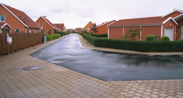
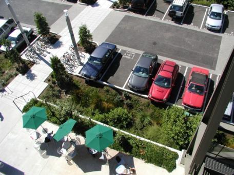
22 Modernizing Development Practices WI DNR photo Narrow streets with angled parking draining to bioretention Street Edge Alternative Green = green roof Blue = bioretention Red = rejuvenated detention basin/ballfields Orange = pervious pavement Conventional Practices Still Have a Place: Wet/Dry Detention/Retention Ponds Traditionally used to mitigate peak flows to predevelopment limits. Problem: Retain significant quantities of water that are released at the highest pre-development rate for a longer period of time. Subjects receiving water to maximum energy for a longer period of time. Still, integral part of stormwater management system. Can be used as an infiltration basin. May be needed to mitigate flooding and reduce peak flow rates in large storms. But definitely can be smaller! 22


23 Wet Detention Ponds to Treat Large Flows Dry Ponds and Extended Detention Ponds having Large Storage capacities to Reduce Runoff Energy 23


24 The manual provides estimated percent removals for each practice, but (1) Percent removals are not applicable in all situations (2) Challenge of pollutants not listed in percent removals Designing the Next Generation of Stormwater Practices International Stormwater BMP Database ( These summaries focus on two separate data analyses: A data set composed of each BMP study s average effluent event mean concentrations (EMCs) over the entire respective monitoring period, grouped by BMP category. A data set comprised of all of the individual effluent EMCs, grouped by BMP category. An assessment was also made of the difference between the median effluent values and the corresponding influent values for both data sets. 24
25 Total Phosphorus (TP) Total Suspended Solids (TSS) 25
26 Total Nitrogen (TN) Example: Potential Treatment Options to Meet a Permit Limit of 20 mg/l TSS, 0.1 mg/l TP, and 1 mg/l TN Detention Basin (DB) TSS TP TN 40 th percentile 30 th percentile 20 th percentile Biofilter (GS) 65 th percentile 30 th percentile 75 th percentile Hydrodynamic Device (HD) 40 th percentile 35 th percentile 20 th percentile Media Filter (MF) 75 th percentile 40 th percentile 80 th percentile Retention Pond (RP) Wetland Basin (WB) 75 th percentile 35 th percentile 40 th percentile 80 th percentile 15 th percentile 20 th percentile 26
27 Calculating Treatment Effectiveness: Devices in Series Final Effluent Quality Controlled by Effluent of Device B. Device A generally has no impact on final water quality, unless substantial reductions in pollutant concentration needed to prevent damage to Device B (sediment forebay, for example) Calculating Treatment Effectiveness: Devices in Parallel Final Effluent Quality Controlled by Weighted Average of Performance of Two Devices (weighted by flow rates through each device). Suggested applications would be providing treatment to some portion of flow to reduce concentrations without providing treatment to entire flow stream. 27
28 Appropriate Combinations of Controls No single control is adequate for all problems! Only infiltration reduces water flows substantially, along with soluble and particulate pollutants. Evapotranspiration devices effective for small storms. Infiltration only applicable in conditions having minimal groundwater contamination potential. Wet detention ponds reduce particulate pollutants and may help control dry weather flows. They do not consistently reduce concentrations of soluble pollutants, nor do they generally solve regional flooding problems (extended release and multiple pond releases). A combination of practices is usually needed, usually as a treatment train (although the practices may be separated by distance on a site). Order of cost (least to most) and ease: Solids control particulate pollutant control dissolved pollutant control. 28