WASTEWATER COLLECTION SYSTEM MASTER PLAN
|
|
|
- Cory Payne
- 5 years ago
- Views:
Transcription
1 CITY OF CLOVIS, CALIFORNIA WASTEWATER MASTER PLAN UPDATE PHASE 3 WASTEWATER COLLECTION SYSTEM MASTER PLAN DRAFT FINAL REPORT APRIL 5, 2017 Prepared Under the Direction of: Mr. Michael J. Harrison, PE, RLS City Engineer City of Clovis Prepared by: Blair, Church & Flynn Consulting Engineers 451 Clovis Avenue, Suite 200 Clovis, CA (559)
2 TABLE OF CONTENTS SECTION 1. EXECUTIVE SUMMARY GENERAL SERVICE AREAS WASTEWATER FLOW PROJECTIONS AND CAPACITIES COLLECTION SYSTEM ANALYSIS AND DESIGN MASTER PLAN PLATS REGIONAL TRUNK SEWER SYSTEM ISSUES FLOW METERING OF CLOVIS TRUNK SEWERS MAJOR ELEMENTS OF CLOVIS WASTEWATER SYSTEM INFRASTRUCTURE SECTION 2. BACKGROUND GENERAL PHASES OF THE WASTEWATER MASTER PLAN SECTION 3. BASE MAPS GENERAL BASE MAP AUGMENTATION SECTION 4. DEVELOPMENT OF WASTEWATER FLOW PROJECTIONS GENERAL MAJOR SERVICE AREAS NODES AND ASSOCIATED TRIBUTARY AREAS SUBAREAS OF DIFFERING PLANNED LAND USE PLATS DEPICTING FLOW GENERATION PARAMETERS FLOW GENERATION COMPUTER MODELING SOFTWARE AVERAGE DAY ANNUAL FLOW BASIS FOR FLOW GENERATION PROJECTIONS PLANNED LAND USE CHARACTERISTICS DEVELOPMENT OF WASTEWATER FLOW GENERATION RATES HYDRAULIC MODEL CALIBRATION FOR EXISTING CONDITIONS WASTEWATER FLOW GENERATION RATES SECTION 5. SEWER PIPELINE ANALYSIS AND DESIGN GENERAL CRITERIA FOR PIPELINE ANALYSIS AND DESIGN ROUGHNESS COEFFICIENT MAXIMUM DEPTH OF FLOW PIPELINE SLOPE PIPELINE DEPTH PIPELINE ANALYSIS SECTION 6. WASTEWATER FLOW SUMMARIES GENERAL FLOW SUMMARIES i
3 SECTION 7. REGIONAL SYSTEM TRUNK SEWER ISSUES GENERAL FOWLER AVENUE TRUNK SEWER AND NORTH AVENUE TRUNK SEWER LEONARD AVENUE TRUNK SEWER SECTION 8. FLOW METERING OF CLOVIS TRUNK SEWERS GENERAL TRUNK SEWER FLOW METERS FLOW METERING DATA OVER TIME SECTION 9. HYDRAULIC MODELING RESULTS AND CAPITAL IMPROVEMENT PROJECT RECOMMENDATIONS GENERAL HYDRAULIC MODELING SERVICE AREA WASTEWATER FLOWS CAPITAL IMPROVEMENT PROJECT RECOMMENDATIONS EXISTING MAJOR PUMP STATIONS AND FORCE MAINS PUMP STATION E PUMP STATION B REHABILITATION AND REPAIR RECOMMENDATIONS LIST OF FIGURES FIGURE 1-1 WASTEWATER SERVICE AREAS FIGURE 1-2 REGIONAL PERSPECTIVE FIGURE 1-3 MAJOR CLOVIS WASTEWATER INFRASTRUCTURE FIGURE 4-1 WASTEWATER SERVICE AREAS FIGURE 4-2 MODELING NODES FIGURE 4-3 TRIBUTARY BOUNDARIES FOR MODELING NODES FIGURE 4-4 DIURNAL CURVES FIGURE 5-1 MODELING SEWERS, NODES AND TRIBUTARY BOUNDARIES FIGURE 7-1 REGIONAL SYSTEM FACILITIES FIGURE 7-2 LEONARD AVENUE CONNECTOR SEWER FIGURE 8-1 CLOVIS ANNUAL AVERAGE METERED FLOW LIST OF TABLES TABLE 1-1 MAJOR CLOVIS SERVICE AREAS TABLE 1-2 FLOW AND TREATMENT CAPACITY SUMMARY TABLE 4-1 MAJOR SERVICE AREA IDENTIFIERS TABLE 4-2 RESIDENTIAL LAND USE DENSITIES TABLE 4-3 MIXED USE PROJECTED USE PROFILE TABLE 4-4 DESIGN WASTEWATER FLOW GENERATION RATES TABLE 5-1 DESIGN PIPELINE SLOPE TABLE 6-1 FLOW AND CAPACITY SUMMARY TABLE 6-2 EXPLANATION OF CAPACITY BALANCE ii
4 TABLE 7-1 CAPACITY SUMMARY FOWLER TRUNK SEWER / NORTH AVENUE TRUNK SEWER TABLE 8-1 CLOVIS TRUNK SEWER FLOW METERS TABLE 8-2 CLOVIS AVERAGE ANNUAL METERED FLOW AND POPULATION TABLE 9-1 REHABILITATION AND REPAIR RECOMMENDATIONS LIST OF APPENDICES APPENDIX A: WASTEWATER MASTER PLAN PLATS APPENDIX B: CAPITAL IMPROVEMENT PROJECT EXHIBITS APPENDIX C: CAPITAL IMPROVEMENT PROJECT LIST AND IMPLEMENTATION SCHEDULE APPENDIX D: CAPITAL IMPROVEMENT PROJECT COST ESTIMATES FOR WASTEWATER CONVEYANCE PROJECTS APPENDIX E: SEWERS INCLUDED IN HYDRAULIC MODEL APPENDIX F: REHABILITATION / REPAIR PROJECTS AND COST ESTIMATES iii
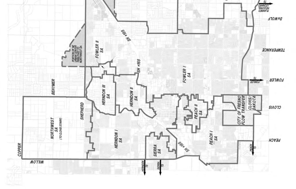
5 SECTION 1. EXECUTIVE SUMMARY 1.1 GENERAL The Wastewater Master Plan Update, Phase 3, (2017 Master Plan) is the latest phase of an effort begun in 1995 to update the City s Wastewater Master Plan. The preceding phase, referred to as the Wastewater Master Plan Update, Phase 2, (2008 Master Plan) was documented in a final report dated June 30, The 2008 Master Plan addressed planned urban growth in the context of the 1993 Clovis General Plan. Wastewater flow generation and sewer flow calculations for the Phase 2 Update were done using a spreadsheet-based hydraulic model. The Wastewater Master Plan Update, Phase 3 addresses planned urban growth in the context of the 2014 Clovis General Plan. Wastewater flow generation and sewer flow calculations for the Master Plan Phase 3 Update were done using a Geographic Information System (GIS) based hydraulic modeling software package. This report documents the Phase 3 Update efforts. Further Wastewater Master Plan Update efforts will be necessary in the future, in response to ongoing community planning and development activity, to the extent that those activities may result in planning and development activity that differs from the 2014 Clovis General Plan, and in response to future general plan updates. The wastewater master plan update process consisted generally of developing design criteria, defining wastewater service areas, developing wastewater flow projections, analyzing and designing collection system pipelines, and summarizing results. 1.2 SERVICE AREAS The Clovis Wastewater Master Plan area contains seven major service areas encompassing a planning area of just over 27,120 acres (see Figure 1-1). Under the 2017 Master Plan, the core of the city is planned to discharge to regional trunk sewers and on to the Fresno-Clovis Regional Wastewater Reclamation Facility (RWRF) in southwest Fresno. By agreement with the City of Fresno, additional treatment capacity can be purchased in the RWRF, as needed. The future growth areas of the city are planned to discharge to the Clovis Sewage Treatment Water Reuse Facility (ST/WRF) in southeast Clovis. 1-1
6 1-2
7 The Clovis service areas are identified in Table 1-1, together with the planned disposition of their wastewater flows. SERVICE AREA Herndon Fowler Sierra Peach Northwest Northeast Southeast TABLE 1-1 MAJOR CLOVIS SERVICE AREAS DISCHARGES TO Regional Herndon Trunk Sewer system leading to Regional Wastewater Treatment Plant Regional Fowler Trunk Sewer and North Avenue Trunk Sewer leading to Regional Wastewater Treatment Plant Regional sewer system leading to Regional Wastewater Treatment Plant Regional Chestnut Trunk Sewer and North Avenue Trunk Sewer leading to Regional Wastewater Treatment Plant Clovis major sewers leading to Clovis Sewage Treatment Water Reuse Facility Clovis major sewers leading to Clovis Sewage Treatment Water Reuse Facility Clovis major sewers leading to Clovis Sewage Treatment Water Reuse Facility Figure 1-2 depicts the Clovis service areas in a regional perspective, with the main existing regional trunk sewers leading to the RWRF graphically indicated. 1.3 WASTEWATER FLOW PROJECTIONS AND CAPACITIES Wastewater flow projections, which are necessary to analyze the existing sewer collection system and plan new facilities to service planned growth, were determined for all areas within the boundaries of the Clovis Sphere of Influence, with the general exceptions of those areas planned for rural residential development or agricultural uses. Wastewater flow generation rates for various land uses were initially carried forward based on the rates employed for the 2008 Master Plan. The rates were then adjusted through a calibration effort that was based on wastewater flow meter data and actual residential development densities for areas of existing residential development. Planned land uses were determined by an examination of the 2014 Clovis General Plan, existing zoning, and existing development. For each service area discharging to the regional trunk sewer system, calculated flow from properties currently developed was calibrated to reasonably correspond with metered flow at the trunk sewer discharge point. Calibration efforts considered overall average daily wastewater flow generation, as well as daily, or diurnal, patterns of wastewater flow variation. Table 1-2 indicates the projected flow, currently acquired capacity and planned capacity for each major service area. The first phase of the Clovis ST/WRF, with Phase 1 average flow capacity of 2.80 million gallons per day (MGD), is included in the calculation of Currently Acquired Capacity along with previously acquired capacity in the regional system. 1-3
8 Figure 1-2 FIGURE 1-2 REGIONAL PERSPECTIVE 1-4
9 TABLE 1-2 FLOW AND TREATMENT CAPACITY SUMMARY (ALL FLOW AND CAPACITY VALUES ARE AVERAGE DAILY FLOW) (2)SEWER SERVICE AREA DEVELOPED FLOW (MGD) PROJECTED FLOW UN- DEVELOPED FLOW (MGD) TOTAL FLOW (MGD) TREATMENT CAPACITY CURRENTLY ACQUIRED AMOUNT (MGD) TOTAL PLANNED AMOUNT (MGD) HERNDON FOWLER (1) SIERRA PEACH NW NE SE TOTALS Flow in excess of MGD from the NW, NE and SE Service Areas is planned to be redirected to the Fowler Trunk Sewer. 2. There is also a minor service area, the Clovis/Dakota Service Area, that is part of a flow transfer agreement with the City of Fresno. The Northwest, Northeast, and Southeast Service Areas are projected to exceed the build-out capacity of the Clovis ST/WRF, based upon the 2014 General Plan land uses. The 2017 Master Plan proposes diversion of a portion of the flow from these service areas to the Fowler Service Area. The Fowler Service Area is capable of acquiring additional capacity in the regional system for both its originally planned service area and the diversion areas. Such additional capacity, available by prior agreement with Fresno, is sufficient based upon current Clovis land use planning per the 2014 General Plan. The additional capacity required to make up the difference between the City of Clovis currently acquired capacity and total planned capacity is as follows: Additional treatment capacity to be acquired in regional system Additional treatment capacity to be acquired in future phases of construction of the Clovis ST/WRF Total additional treatment capacity MGD MGD MGD Additional treatment capacity at the RWRF can be acquired in increments of about 1.0 MGD as needed by Clovis. Additionally, Clovis has agreed to participate in the cost of construction of up to 3 MGD of additional capacity in the North Avenue Trunk Sewer, which receives flow from the Fowler Trunk Sewer and discharges into the RWRF. Agreement provisions specify that the Clovis share of related project costs shall reflect Clovis proportional share of flow capacity in any new capacity enhancing project. 1-5
10 Clovis currently owns capacity in all other regional trunk sewers for Clovis projected buildout flow per the Master Plan. 1.4 COLLECTION SYSTEM ANALYSIS AND DESIGN Criteria for pipeline analysis and design were established, including hydraulic elements and pipeline depth limitations. All existing sewers 10-inches and larger in diameter were analyzed, together with some 8-inch diameter sewers where necessary to extend wastewater service to all tributary areas. All proposed new major sewers were also analyzed and sized. A hydraulic modeling computer software package was utilized to analyze the hydraulics of individual segments of the sewers, utilizing the established hydraulic criteria. The previous method of analyzing the wastewater system for the 2008 Master Plan was Microsoft Excel spreadsheet based system. The software used for the 2017 Master Plan is H2OMAP Sewer Suite 10.5, Update No. 10, by Innovyze, which has many features not available using the spreadsheet-based model, including the ability to incorporate geographic information system (GIS) data. The Innovyze software was utilized to analyze flows throughout the current and proposed service areas. Flows were generated at predetermined loading manholes, from adjacent land use areas, using the loading parameters specific to each land use. 1.5 MASTER PLAN PLATS The basic graphic element of the Master Plan consists of a set of Master Plan plats. These plats extend over the entire area of the 2014 Clovis General Plan designated for urban development. The Master Plan plats include layers from the Clovis Geographic Information System (GIS), and were created on the identical coordinate system. The plats were developed in two distinct visibility formats, as follows: Flow Generation Parameters. These sheets depict service area boundaries, and within each sub-area boundary, planned land use, area in acres, and estimates of percentage developed. These drawings were rectified to be consistent with, and form a supporting background for, the Wastewater Collection System Facility Element plats. System Facility Elements. These sheets depict the physical elements of the wastewater collection system, including: all existing sewers and manholes; all planned sewers that are necessary to extend sewer service to the location of the node from which sewer service is provided for every sewer service sub-area; analysis nodes; service area boundaries and other information. The plats are produced in a 24-inch high by 36-inch wide sheet format for ease of handling. The scale of the mapping is 1-inch equals 600 feet, which provides a compromise between readability and number of sheets to handle. 1-6
11 Reduced copies of the Master Plan plats are appended to this report as Appendix A, and full size copies accompany the report as a separate package. 1.6 REGIONAL TRUNK SEWER SYSTEM ISSUES The regional Fowler Avenue Trunk Sewer and downstream interconnected North Avenue Trunk Sewer, which carry flow discharging from the Fowler Service Area, have outstanding issues yet to be finally resolved with the City of Fresno. Complicating these issues is another recently planned regional trunk sewer, the Leonard Trunk Sewer, which may also discharge to the regional North Avenue Trunk Sewer. Section 7 examines these issues, including the effects of the 2002 joint powers agreement between the Cities of Clovis and Fresno For Temporary Exchange of Sewer Capacity in the North Avenue and Fowler Avenue Trunk Sewer Mains. This agreement also affects Clovis master planned connection to the regional Leonard Trunk Sewer, which would provide the benefits of backup capability, operational alternatives and redundancy to a major portion of Clovis wastewater system. 1.7 FLOW METERING OF CLOVIS TRUNK SEWERS The Herndon, Peach, Sierra, and Fowler trunk sewers are metered by Fresno where they enter the regional system. The metering data over the past twenty one years indicates that the sum total flow of the four trunk sewers has not increased in direct proportion to the population increase in Clovis. Other flow meter data has been obtained from points within the Clovis wastewater collection system, and that data also supports the flow quantity trends indicated by the meters at the discharge points to the regional system. This is believed to be the result of an overall trend toward water conservation by Clovis users, together with the result of the utilization of water conserving fixtures in new construction and remodels. Other potential reasons may include changes in average household size over time. Wastewater flow generation rates historically utilized for Clovis wastewater master planning efforts were initially established in However, actual wastewater flow generation rates have decreased significantly since then, based on flow meter data and the apparent variation from population growth. Wastewater flow generation rate calibration was done to adjust wastewater flow generation rates as indicated by flow meter data. Reasons and methods for adjustment of wastewater flow generation rates for the master plan update are outlined in Section CAPITAL IMPROVEMENT PROJECT RECOMMENDATIO Although there are minor exceptions, major elements of the Wastewater Master Plan generally are considered to be existing trunk sewers 24 inches in diameter and larger, planned trunk sewers 15 inches in diameter and larger, existing pump stations and force mains that are necessary for the diversion of flow between service areas, and all planned pump stations and force mains. These are depicted on Figure

12 IGURE 1-4 MAJOR CLOVIS WASTEWATER INFRASTRUCTURE Wastewater Master Plan Update, Phase 3 1-8
13 Section 9 includes discussion of these facilities, including the specific planned function of major existing pump stations, and all planned pump stations and force mains. Although much of the major Clovis wastewater infrastructure is in place, a number of key elements remain to be constructed in advance of new development, particularly in the outlying future growth areas. Section 9 provides recommendations and cost estimates for related Capital Improvement Projects and Rehabilitation and Repair Projects. 1-9
14 SECTION 2. BACKGROUND 2.1 GENERAL The Wastewater Master Plan Update, Phase 3, (2017 Master Plan) is the latest phase of an effort begun in 1995 to update the City s Wastewater Master Plan. The preceding phase, referred to as the Wastewater Master Plan Update, Phase 2, (2008 Master Plan) was documented in a final report dated June 30, The 2008 Master Plan addressed planned urban growth in the context of the 1993 Clovis General Plan. Wastewater flow generation and sewer flow calculations for the Phase 2 Update were done using a spreadsheet-based hydraulic model. The Wastewater Master Plan Update, Phase 3 addresses planned urban growth in the context of the 2014 Clovis General Plan. Wastewater flow generation and sewer flow calculations for the Master Plan Phase 3 Update were done using a Geographic Information System (GIS) based hydraulic modeling software package. This report documents the Phase 3 Update efforts. The wastewater master plan update process consisted generally of developing design criteria, defining wastewater service areas, developing wastewater flow projections, analyzing and designing collection system pipelines, and summarizing results. The Clovis Wastewater Master Plan Update has been a process designed to provide a course of action for the City of Clovis with respect to wastewater service needs, in conformance with the 2014 Clovis General Plan and its planning horizon. 2.2 PHASES OF THE WASTEWATER MASTER PLAN Phases of the Wastewater Master Plan efforts have included the following: Phase 1-A Present Wastewater Flows, Projected Flows and Trunk Sewer Capacities for Existing Trunk Sewer Service Areas Date of Report: June, 1995 Phase 1-B Wastewater Master Plan Update Date of Report: November, 1996 Phase 2 Wastewater Collection System Master Plan Date of Report: June 30, 2008 Phase 3 Wastewater Master Plan Update, Phase 3 Date of Report: March 31, 2017 Phase 1-A concentrated on analyzing wastewater flow generation from various land uses within Clovis, together with preliminarily assessing then-current wastewater 2-1
15 flows, existing trunk sewer capacities, projected buildout flow from existing trunk sewer service areas, and the general relationship of the quantity of flow to be generated by future growth areas to existing trunk sewer capacity. Phase 1-B analyzed, evaluated and presented conceptual alternatives for wastewater service to Clovis, for the entire 1993 Clovis General Plan area. This included options for acquisition of new wastewater system treatment capacity, including potential Clovis satellite wastewater treatment facilities with associated water reclamation elements. Wastewater collection systems were incorporated into the Phase 1-B study only to the extent of concept level analysis of the various alternatives presented. Phase 2 provided a more detailed analysis of existing and proposed elements of the Clovis wastewater collection system. It provided a wastewater collection system master plan for all areas which were proposed for urban growth in the 1993 Clovis General Plan. The collection system master plan presented was based upon Modified Alternate 5 of the Phase 1-B study. The plan was designed to provide for the potential of interim temporary service to some areas where ultimate service may be infeasible for a number of years. Phase 3 provides an analysis of existing and proposed elements of the Clovis wastewater collection system for the 2014 General Plan. It provides a collection system master plan for all areas which are proposed for urbanization in the 2014 Clovis General Plan. The plan is designed to provide sewer service planning in conformance with the 2014 Clovis General Plan and its planning horizon. Further Wastewater Master Plan Update efforts will be necessary in the future, in response to ongoing community planning and development activity, to the extent that those activities may result in planning and development activity that differs from the 2014 Clovis General Plan, and in response to future general plan updates. 2-2
16 SECTION 3. BASE MAPS 3.1 GENERAL A series of AutoCAD base maps produced for the 2008 Master Plan were updated to extend over the entire area of the 2014 Clovis General Plan designated for urban development. Base information for the master digital model was imported from the Clovis Geographic Information System (GIS) into AutoCAD. Imported layers included those for parcel, street, sewer main, sewer manhole, and general plan elements of the GIS. The base maps, or plats, are at a scale of 1-inch equals 600 feet, which provide a compromise between readability and number of sheets to handle. A cover sheet index map was created from the same digital model, displayed at a scale of one-inch equals 2,000 feet. 3.2 BASE MAP AUGMENTATION The base mapping created by the Clovis GIS data was augmented to create useful plats for the master planning process. The Fresno County GIS was utilized to provide parcel information in certain areas outside the limits of the Clovis GIS. The County GIS information was graphically adjusted, by rotating and stretching, to fit the Clovis GIS at the interface between the two mapping areas. The graphically rectified County information is not considered be at the level of accuracy of the Clovis GIS data, and only serves as a guide to parcelization outside the Clovis GIS. For all existing sewers, the pipeline diameter and direction of flow were extracted from the GIS. This information was reflected on the base maps by flow direction arrow and text. This allows the use and interpretation of the maps in most cases without accessing the computer modeling software. Text was added to designate major street names and major landmarks, such as freeways and schools. Text size was selected to be readable on both the plat maps and the cover sheet index map. Information from Fresno Metropolitan Flood Control District was used to develop ground contours using topographic mapping and future design gutter grades. Contour lines on existing hard copy topographic maps were digitized and rectified into the base mapping, allowing approximations of depth to be made for the design of proposed sewers. 3-1
17 SECTION 4. DEVELOPMENT OF WASTEWATER FLOW PROJECTIONS 4.1 GENERAL Wastewater flow projections, which are necessary to analyze the existing sewer collection system and plan new facilities to service planned growth, were determined for all areas of the 2014 Clovis General Plan designated for urban development. Major wastewater collection system service area boundaries were established and documented. Within each major service area, nodes were established at key locations on existing and proposed sewers, and boundaries of areas tributary to each node were determined. Within each node tributary area, boundaries of differing planned land uses were determined. The percentage of development within each subarea of differing planned land use was estimated. The information so developed was documented and plotted on plats. Criteria for flow generation projections were developed, utilizing unit wastewater flow generation rates for the basic major land use categories that were modified from the 1995 Phase 1-A study. Single family residential units flow generation rates were revised in this update based upon residential flow monitoring investigations and buildout flow projections versus population projections. 4.2 MAJOR SERVICE AREAS The Wastewater Master Plan area contains seven major service areas encompassing a planning area of just over 27,120 acres, as shown on Figure 4-1. Under the 2017 Master Plan, the core of the city is planned to discharge to regional trunk sewers and on to the Fresno-Clovis Regional Wastewater Treatment Plant (RWRF) in southwest Fresno. By agreement with the City of Fresno, additional treatment capacity can be purchased in the RWRF, as needed. The future growth areas of the city are planned to discharge to the Clovis Sewage Treatment Water Reuse Facility (ST/WRF) in southeast Clovis. Four service areas are connected to existing regional trunk sewers, and three service areas serving growth areas of the City will serve to the Southeast Clovis Sewage Treatment/Water Reuse Facility (ST/WRF). Boundaries of the seven major service areas were determined by an examination of the existing sewer system together with ground contours, physical features, and planned land uses from the 2014 General Plan. Boundaries were then plotted on the Master Plan plats. The Clovis wastewater collection system service areas include the following: Herndon Service Area: The Herndon Service Area is that area which is ultimately planned to discharge to the regional Herndon Trunk Sewer. The regional Herndon Trunk Sewer extends westerly in Herndon Avenue from Willow Avenue, ultimately discharging to the Regional Wastewater Treatment Plant located southwesterly of the City of Fresno. 4-1

18 4-2
19 Fowler Service Area: The Fowler Service Area is that area which is ultimately planned to discharge to the regional Fowler Trunk Sewer. The regional Fowler Trunk Sewer extends southerly in Fowler Avenue from an existing monitoring station located between Sussex and Griffith Avenue (about ¼ mile south of Ashlan Avenue), ultimately discharging to the Regional Wastewater Treatment Plant located southwesterly of the City of Fresno. Sierra Service Area: The Sierra Service Area is that area which is ultimately planned to discharge to the regional Sierra Trunk Sewer. The regional Sierra Trunk Sewer extends westerly in Sierra Avenue from Willow Avenue, ultimately discharging to the Regional Wastewater Treatment Plant located southwesterly of the City of Fresno. Peach Service Area: The Peach Service Area is that area which is ultimately planned to discharge to the regional Peach Trunk Sewer. The regional Peach Trunk Sewer extends westerly in Dakota Avenue from Peach Avenue, ultimately discharging to the Regional Wastewater Treatment Plant located southwesterly of the City of Fresno. Northwest Service Area: The Northwest Service Area is bounded generally by Willow Avenue on the west, Copper Avenue on the north, Sunnyside Avenue alignment on the east, and by the northerly boundary of the Herndon Service Area on the south. There is also included in the master plan for the Northwest Service Area a trapezoidal shaped portion of the planned Northeast Urban Village lying north of Shepherd Avenue and westerly of the Big Dry Creek Reservoir. Under the Master Plan, wastewater from the Northwest Service Area will flow by gravity to a proposed pump station near the intersection of Willow and Shepherd Avenues, which will discharge to a force main leading east in Shepherd Avenue to the DeWolf Avenue Alignment. At this point flow will enter a gravity system discharging south into the Southeast Service Area system and ultimately to the Clovis Sewage Treatment/Water Reuse Facility (ST/WRF) located on the north side of Ashlan Avenue, between Thompson and McCall Avenues. Southeast Service Area: The Southeast Service Area is bounded generally by the current Clovis Sphere of Influence line on the north, east, and south, and by the easterly boundary of the Fowler Service Area on the west. Under the Master Plan, wastewater flow from the Southeast Service Area, together with flow from the Northwest Service Area and Northeast Service Area, will discharge to the Clovis ST/WRF. Northeast Service Area: The Northeast Service Area is bounded generally by Herndon Avenue on the south, Copper Avenue on the north, Thompson Avenue and SR-168 on the west, and the Friant-Kern Canal and approximate Bethel Avenue Alignment on the east. Under the Master Plan, flow from this service area will discharge west and then ultimately south to the Clovis ST/WRF. 4-3
20 Another service area, though not considered a major service area, exists as follows: Clovis/Dakota Service Area: The Clovis/Dakota Service Area is ultimately planned to discharge into the same sewer as the Peach Trunk Sewer east of the intersection at Chestnut and McKinley Avenues. This service area is part of a flow transfer agreement with the City of Fresno. The Clovis/Dakota Service Area ultimately discharges to the Regional Wastewater Treatment Plant located southwesterly of the City of Fresno. 4.3 NODES AND ASSOCIATED TRIBUTARY AREAS Nodes were assigned at key points for analysis along existing and proposed sewers. All sewers 10-inches and larger in diameter were analyzed, together with some 8-inch diameter sewers where necessary to extend wastewater service to all tributary areas. At existing sewer manholes, the established Clovis manhole designation number was utilized for node identification, prefixed by the major service area identifier. For nodes on proposed sewers, a designation was assigned utilizing the Clovis plat number for the location together with a letter, also prefixed by the major service area identifier. Nodes and modeled sewers are generally depicted on Figure 4-2, and are shown in detail on the Master Plan plats. Major service area identifiers were established as indicated in Table 4-1: TABLE 4-1 MAJOR SERVICE AREA IDENTIFIERS MAJOR SERVICE AREA Herndon Fowler Sierra Peach Northeast Northwest Southeast IDENTIFIER H F S P NE NW SE The Clovis/Dakota Service Area, not considered a major service area, was assigned the identifier of "C". The boundaries of the tributary areas of each node for existing sewers were established by an examination of the existing sewer system together with ground contours, physical features and planned land uses. A similar process was utilized for nodes on proposed sewers. For each node, a tributary service area identifier corresponding to the associated node, together with the boundary of the tributary area, were then plotted on the master plan plats. Tributary service boundaries throughout the planning area are depicted on Figure 4-3, and identified in detail on the Master Plan plats. 4-4
21 4-5
22 FIGURE 4-3 FIGURE 4-3 TRIBUTARY BOUNDARIES FOR MODELING NODES 4-6
23 4.4 SUBAREAS OF DIFFERING PLANNED LAND USE Within the boundary of each node s tributary area, subareas were established for each differing planned land use. For the purposes of estimating wastewater flow generation, planned land uses were determined by an examination of the 2014 Clovis General Plan, existing zoning, and existing development. The boundaries of differing land use subareas so determined were plotted on a specific mapping layer for display and for use in hydraulic modeling. The percentage of currently developed land (as opposed to undeveloped land) within the boundary of each subarea of differing planned land use was estimated and recorded. This was accomplished by examination of aerial photography furnished by Google Earth images dated March 2015, augmented by visual field reconnaissance. 4.5 PLATS DEPICTING FLOW GENERATION PARAMETERS Flow generation parameters including planned land use subarea boundaries, planned land use, area in acres, and estimates of percentage developed, were plotted and developed into a set of plats. The plats were rectified to be consistent with, and form a supporting background for, the Wastewater Master Plan System Facility Elements plats. 4.6 FLOW GENERATION COMPUTER MODELING SOFTWARE The software used for the hydraulic modeling of the City's wastewater collection system for the 2017 Master Plan is H2OMAP Sewer Suite 10.5, Update No. 10 (H2OMAP Sewer), a software product of the firm Innovyze. An evaluation of hydraulic modeling software packages was documented in the July 23, 2014 technical memorandum "City of Clovis Wastewater Master Plan Update Phase 3, Hydraulic Modeling Software Evaluation". H2OMAP Sewer was recommended as the preferred hydraulic modeling platform, and the City has since selected and acquired H2OMAP Sewer. H2OMAP Sewer replaced the custom Microsoft Excel spreadsheet model developed in the Phase 2 Master Plan. The Phase 3 and Phase 2 models were run side by side where feasible, to verify the general validity of results from the replacement software. H20MAP Sewer utilizes the Manning and Hazen-Williams equations to calculate flow in gravity mains and force mains respectively. Sewer analysis for extended period simulations (EPS) is conducted by the modeling software using a simplified method of the Saint-Venant equations, along with the Muskingum-Cunge equation. The EPS simulation utilizes diurnal curves that have been calibrated to reflect actual conditions as represented by flow meter data for the Clovis wastewater collection system. During sewer modeling activities, it was discovered that the Innovyze load allocator was not distributing wastewater loads properly. Innovyze was unable to develop a solution for the problem, but was able to provide a workaround using Microsoft Excel. The workaround performs the function of the load allocator and transfers the correct 4-7
24 loading values by copying a column in an Excel spreadsheet and pasting it into the Innovyze software input data. Innovyze has indicated that further efforts by their staff will not be undertaken to produce a solution to this issue since a workaround is available, but that forthcoming software updates will correct the issue. 4.7 AVERAGE DAY ANNUAL FLOW BASIS FOR FLOW GENERATION PROJECTIONS In the Phase 1-B Wastewater Master Plan Update of November, 1996, the following parameters of wastewater flow were identified: Average Day Annual Flow. This is the average daily flow based on the calendar year. Average Dry Weather Flow. This is the average flow occurring over the three consecutive lowest flow months of the year. The Average Dry Weather Flow for Clovis typically occurs in April, May and June. Average Day Maximum Month Flow. This is the average daily flow occurring during the maximum flow month of the year. The Average Day Maximum Month Flow for Clovis has historically occurred during the month of September during the fruit processing season. The timing of this may change if operations at fruit processing facilities change over time. Peak Hour Wet Weather Flow. This is the peak hour flow resulting from the design rainfall event. The Peak Hour Wet Weather Flow typically occurs during the wet weather period of December through March, and is ultimately limited by the hydraulic capacity of the trunk sewer system. All flow projections for the 2017 Master Plan reflect the Average Day Annual Flow, also referred to as the Average Daily Flow. This is used in the master plan design because it is most representative of the Clovis sewer system. Following are some of the factors which influence this: The average day maximum month flow is accounted for in the master plan, inasmuch as the calculations for flow projections for the Clovis system include a year-round allocation for the major fruit processing facility. Calibration of current flow in the model for each major service area was based upon selection of metered flow considering the higher value metered months for comparison with projected flow, which largely compensates for the typically minimal inflow and infiltration (I&I) rates experienced in the Clovis wastewater collection system. Groundwater levels in Clovis are well below sewer depths, so groundwater infiltration is not a design factor that was included. Use of the Average Day Annual Flow for all average daily flow projections for the 2017 Master Plan is expected to produce slightly conservative results that are reasonably 4-8
25 reflective of actual conditions in the collection system. Since actual wastewater flow generation rates appear to be declining somewhat over time, as the result of implementation of water conservation measures and the trend for use of modern reduced water use fixtures for new and remodeled construction, conservatism can probably be expected to increase over time as actual wastewater flow generation continues to decrease. 4.8 PLANNED LAND USE CHARACTERISTICS The design wastewater flow generation rates for the major categories of land use were further developed into projected flow generation rates for the various categories of land use identified in the 2014 General Plan. The range of residential densities and projected densities utilized in the Phase 3 study for each residential land use designation are indicated in Table 4-2. TABLE 4-2 RESIDENTIAL LAND USE DENSITIES LAND USE DESIGNATION RANGE OF RESIDENTIAL DENSITIES (Dwelling Units Per Acre) LOW MAXIMUM PROJECTED Agricultural Rural Very Low Residential Low Residential Medium Residential Medium High Residential High Residential Very High Residential Mixed Use Village Mixed Use Village (FA-4) Mixed Use Village (FA-8) Mixed Use Village (FA-11) Mixed Use Business Campus Mixed Use Business Campus (FA-5) Mixed Use Business Campus (FA-10) Mixed Use Business Campus (FA-14) Where the Mixed Use Village and Mixed Use Business Campus land use designations include a modifier, such as (FA-4) for example, this indicates that the corresponding land use has different characteristics than the ordinary unmodified Mixed Use Village and Mixed Use Business Campus land uses, based on the 2014 General Plan. The modifier is a reference to the Focus Area content of the 2014 General Plan that relates to a particular area of planned Mixed Use Village or Mixed Use Business Campus land use, where (FA-4) refers to Focus Area 4, for example. The mixed use land use designations include a combination of commercial, office, industrial, and residential uses. Projected use profiles for the Mixed Use Village and Mixed Use Business Campus designations are shown in Table
26 TABLE 4-3 MIXED USE PROJECTED USE PROFILE LAND USE DESIGNATION PROJECTED USE PROFILE COMM. OFFICE INDUST. RES. Mixed Use Village 60% 25% 0% 15% Mixed Use Village (FA-4) 40% 35% 0% 25% Mixed Use Village (FA-8) 60% 10% 0% 30% Mixed Use Village (FA-11) 0% 45% 45% 10% Mixed Use Business Campus 10% 35% 35% 20% Mixed Use Business Campus (FA-5) 20% 35% 20% 25% Mixed Use Business Campus (FA-10) 0% 75% 0% 25% Mixed Use Business Campus (FA-14) 5% 40% 40% 15% 4.9 DEVELOPMENT OF WASTEWATER FLOW GENERATION RATES HYDRAULIC MODEL CALIBRATION FOR EXISTING CONDITIONS The wastewater flow generation rates used for hydraulic modeling were initially developed based on the flow generation rates used for the Wastewater Master Plan Update, Phase 2. Calibration efforts were conducted using flow meter data from three sources: 1. Recent flow meter data provided by the City of Clovis for the four discharges from the Clovis wastewater collection system to the Fresno-Clovis regional wastewater collection system at the Herndon Trunk Sewer, the Sierra Trunk Sewer, the Peach Trunk Sewer, and the Fowler Trunk Sewer (Flow Meter Data Source No. 1). Section 8 provides additional information relative to this flow meter data. 2. Flow meter data for sewers serving three residential subdivisions, as reported in the April 6, 2015 technical memorandum "City of Clovis Wastewater Master Plan Update Phase 3, Flow Monitoring Results and Analysis" (Flow Meter Data Source No. 2). 3. Flow meter data for sewers serving areas of central Clovis, as reported in the April 11, 2016 technical memorandum "City of Clovis Wastewater Master Plan Update Phase 3, Central Clovis Specific Plan Sewer Capacity" (Flow Meter Data Source No. 3). The spreadsheet-based hydraulic model for the 2008 Master Plan was used for an initial calibration effort. The 2008 Master Plan Model was updated to reflect current existing land uses, and model output was compared to flow meter data from Flow Meter Data Source No. 1. Wastewater flow generation rates for all land uses except for schools were adjusted generally downward until hydraulic calculation results were approximately aligned with flow meter data. The wastewater flow generation rates developed as described above were further adjusted where appropriate to account for the fact that actual existing residential development densities in certain areas are in some cases different from the average residential densities that would otherwise be 4-10
27 expected for the same land uses. These calibration efforts resulted in wastewater flow generation rates generally 35 percent lower than those used for the 2008 Master Plan Model, and up to 50 percent lower for the central Clovis area. A final calibration was done with the hydraulic modeling software used for the 2017 Master Plan using flow meter data from the same sources. Final calibration was a twostep process, with the first step being calibration for a steady state analysis based on average daily flow. The second step involved diurnal curve calibration to result in modeled flow rate variations throughout the course of a day that closely match the actual flow rate variations derived from flow meter data, for both weekday and weekend conditions, for each service area. Diurnal curves represent the variation in wastewater flow generation rates over the course of a typical day. Diurnal curves for residential areas were developed based on Flow Metering Data Source No. 2. Each service area has a residential diurnal pattern that resembles the pattern derived from the residential metering, although it has been modified through calibration using 2015 flow meter data. Figure 4-4 shows residential wastewater flow generation diurnal curves developed on the basis of the flow monitoring data and calibration efforts. Typical diurnal curves were developed for businesses, schools, and the Wawona frozen food facility as shown in Figure 4-4. The business and school diurnal curves were developed based largely on engineering reference literature for wastewater flow analysis for business and school land uses, and were used for Phase 3 Model development. Wastewater flow generation rates for school land uses were not adjusted during calibration, because the rates used for schools for the 2008 Master Plan were based on an engineering study done to determine flow generation rates for Clovis schools, and it was felt that an adjustment should only be made if it is supported by another such study WASTEWATER FLOW GENERATION RATES Residential wastewater flow generation rates used for the 2008 Master Plan were based on a value of 270 gallons/day/unit for single family residential land uses, and 220 gallons/day/unit for multi-family residential land uses. The calibration effort described above resulted in a determination that existing residential land uses overall are currently generating average wastewater flows that are approximately 35% lower, based on Flow Meter Data Source No. 1, from the trunk sewer flow meters at the four discharges from the Clovis wastewater collection system. This corresponds to lower rates of approximately 175 gallons/day/unit for single family residential land uses, and 142 gallons/day/unit for multi-family land uses. Based on corresponding estimated average occupancies of 3.16 people/unit and 2.30 people/unit, respectively, these rates correspond to approximately 55 gallons per capita per day (gpcd) and 62 gpcd, respectively, for these two categories of residential land uses. 4-11
28 Flow Ratio (Instantaneous / Average) :00 1:00 2:00 3:00 4:00 5:00 6:00 7:00 8:00 9:00 Business School Wawona Fowler Residential 10:00 FIGURE 4-4 DIURNAL CURVES Flow Meter Data Source No. 2, from the metering done in three residential subdivisions, resulted in average residential wastewater flow generation rates ranging from 162 to 210 gallons/day/unit. The average single family residential rate of 175 gallons/day/unit derived in calibration is approximately 8% higher than the low end of that range, and approximately 17% lower than the high end of that range. Flow Meter Data Source No. 3, from the metering done at three locations in sewers serving areas of central Clovis, resulted in average residential wastewater flow generation rates that are estimated to range from 83 to 132 gallons/day/unit. The single family residential rate of 175 gallons/day/unit derived in calibration is approximately 33% above the high end of that range. Clearly, actual residential wastewater flow generations rates can be expected to vary widely throughout the City. Given the good correlation with Flow Meter Data Source No. 1, the trunk sewer flow meters at the four discharges from the Clovis wastewater collection system, it is recommended that wastewater flow generation rates of 175 gallons/unit/day for single family residential and 142 gallons/unit/day for multi-family residential be used as the basis for developing area-based residential wastewater flow generation rates for new development. Similarly, it is recommended that wastewater flow generation rates derived from hydraulic model calibration efforts be used as the basis for developing area-based 11:00 Time 12:00 13:00 14:00 15:00 16:00 17:00 18:00 19:00 20:00 21:00 22:00 23:00 0:
29 wastewater flow generation rates for non-residential land uses. The foregoing recommendations result in the area-based wastewater flow generation rates shown in Table 4-4, which are recommended for wastewater collection system planning and design efforts for new development in the Clovis wastewater collection system service areas. TABLE 4-4 DESIGN WASTEWATER FLOW GENERATION RATES LAND USE DESIGNATION PROJECTED FLOW GENERATION RATE (MGD=MILLION GALLONS PER DAY) ALL AREAS ARE IN GROSS ACRES Agricultural MGD/ACRE General Commercial MGD/ACRE High Density Residential MGD/ACRE Industrial MGD/ACRE Low Density Residential (Unclassified) MGD/ACRE Fowler Service Area MGD/ACRE Herndon I Service Area MGD/ACRE Herndon II Service Area MGD/ACRE Sierra Service Area MGD/ACRE Medium Density Residential (Unclassified) MGD/ACRE Clovis Service Area MGD/ACRE Fowler Service Area MGD/ACRE Herndon I Service Area MGD/ACRE Herndon II Service Area MGD/ACRE Peach I Service Area MGD/ACRE Peach II Service Area MGD/ACRE Sierra Service Area MGD/ACRE Medium High Density Residential MGD/ACRE Mixed Use Business Campus MGD/ACRE Mixed Use Business Campus (FA-5) MGD/ACRE Mixed Use Business Campus (FA-10) MGD/ACRE Mixed Use Business Campus (FA-14) MGD/ACRE Mixed Use Village MGD/ACRE Mixed Use Village (FA-4) MGD/ACRE Mixed Use Village (FA-8) MGD/ACRE Mixed Use Village (FA-11) MGD/ACRE Neighborhood Commercial MGD/ACRE Office MGD/ACRE Open Space MGD/ACRE Public/Quasi-Public Facilities MGD/ACRE Park MGD/ACRE Rural Residential MGD/ACRE Elementary School MGD/STUDENT Intermediate School MGD/STUDENT High School MGD/STUDENT Very High Density Residential MGD/ACRE Very Low Density Residential MGD/ACRE Water MGD/ACRE MGD = Million Gallons Per Day, AC = Acre, STU = Student 4-13
30 SECTION 5. SEWER PIPELINE ANALYSIS AND DESIGN 5.1 GENERAL All sewers 10-inches and larger in diameter were analyzed, together with some 8-inch diameter sewers where necessary to extend wastewater service to all tributary areas. Criteria for pipeline analysis and design were established, including hydraulic elements and pipeline depth limitations. Information relative to existing sewers to be analyzed was extracted from the City of Clovis Geographic Information System (GIS). The computer modeling software analyzed the hydraulics of individual segments of these sewers, utilizing linked information from the flow generation model for the associated sewershed. Similarly, design data for proposed sewers were entered into the hydraulic model, and also analyzed. 5.2 CRITERIA FOR PIPELINE ANALYSIS AND DESIGN Design criteria utilized for the analysis of existing sewers and for the design of proposed sewers were established, as outlined below ROUGHNESS COEFFICIENT All gravity flow pipeline hydraulic design is to be based upon Manning s equation, using a roughness coefficient of All force main flow calculations are based on a Hazen-Williams roughness coefficient "C" value of MAXIMUM DEPTH OF FLOW For the analysis of existing sewers, the maximum allowable relative depth ratio, calculated as the depth of flow divided by pipe diameter (d/d), was taken to be For the sizing design of planned sewers, the maximum allowable d/d ratio was taken to be PIPELINE SLOPE For design purposes, gravity flow pipeline slope shall be as indicated in Table 5-1. Steeper pipeline slopes shall be used wherever feasible, subject to pipeline depth considerations. The maximum pipe slope for all diameters should be such that the wastewater flow velocity does not exceed 10 feet per second. 5-1
31 DIAMETER OF SEWER STANDARD SLOPE TABLE 5-1 DESIGN PIPELINE SLOPE MINIMUM SLOPE DIAMETER OF SEWER STANDARD SLOPE MINIMUM SLOPE PIPELINE DEPTH The target minimum depth from existing ground surface to invert elevation of gravity sewers at shallowest locations shall be no less than 6 feet. This may not be possible in some locations where the depth of existing sewers, or the local topography, do not allow this minimum depth. The target maximum depth from existing ground surface to invert elevation of gravity sewers shall be no greater than 20 feet, except where unavoidable because of service area topography. In no case shall sewers be designed for depths greater than 30 feet. It was necessary to design sewers up to 30 feet deep in the Northeast Service Area due to irregular terrain conditions in order to ensure service to all areas in the proposed growth area. 5.3 PIPELINE ANALYSIS All sewers 10-inches and larger in diameter were analyzed, together with some 8-inch diameter sewers where necessary to extend wastewater service to all tributary areas. Pipeline segments between existing and proposed manholes were individually analyzed. Modeling nodes, modeled pipelines and tributary boundaries over the planning area are shown schematically on Figure 5-1, and in greater detail on the Master Plan plats. All flow generated by a sub-service area is assumed to enter the analyzed segment at the upstream-most node in the sub-service area. Information relative to existing sewers to be analyzed was extracted from Geographic Information System (GIS) data provided by the City. This information included pipeline segment diameter, slope, and length. It was originally anticipated that the City's GIS data for the entire existing wastewater collection system would be used for the hydraulic model, with minor adjustments where necessary, and that every City sewer regardless of size would be represented in the model. However, in attempting to use the City's data, a number of problems were encountered that prohibited direct use of the data as planned. One of the most significant problems is the use of two different elevation datums that have been used for the entry of the GIS data, with no reliable way to consistently determine which datum was used for a particular entity. 5-2
32 Figure 5-1 FIGURE 5-1 MODELING SEWERS, NODES AND TRIBUTARY BOUNDARIES 5-3
33 Blair, Church & Flynn attempted to develop several solutions that could analyze, find and repair affected entities in the GIS data, but largely without success. In order to be able to move forward with hydraulic model development, a decision was made to eliminate all sewers smaller than 10 inches in diameter from the GIS data used for the model, which significantly reduced the number of sewer segments included in the data. Exceptions were made for a limited number of smaller sewers where they were considered essential for the accurate modeling of particular parts of the system. The remaining GIS data was then evaluated manually, segment by segment, to locate and repair data faults so that the GIS data could be used with H2OMAP Sewer. The elevation datum for the GIS data used for hydraulic modeling is the National Geodetic Vertical Datum of 1929 (NGVD29), rather than North American Vertical Datum of 1988 (NAVD88) which is currently the standard elevation datum for the City. This was done for several reasons: Most of the sewers represented by the GIS data were designed and constructed based on NGVD29. Most of the City's GIS data for those sewers contains elevations that are based on NGVD29. The spreadsheet-based hydraulic model used for the 2008 Master Plan was based on NGVD29, and that model was used as an important aid for the calibration and validation of the H2OMAP Sewer model for the 2017 Master Plan. Conversion between NGVD29 and NAVD88 elevations cannot be done accurately by the application of a single global adjustment factor, because the conversion is dependent on the horizontal location of the point in question. 5-4
34 SECTION 6. WASTEWATER FLOW SUMMARIES 6.1 GENERAL Summaries of projected flow utilizing the wastewater flow generation rates indicated in Section were prepared for the major service areas, after calibration of the model for the four service areas which are metered where they exit Clovis and enter the Regional System. 6.2 FLOW SUMMARIES Table 6-1 contains flow summaries for all of the major sewer service areas. The flow summaries include estimates of flow from properties currently developed, from properties currently undeveloped, and for total projected flow at buildout. All flows reported are average daily flows in millions of gallons per day (MGD). Table 6-1 also contains flow capacity summaries for all of the major sewer service areas. Capacity is presented both as currently acquired, and as total planned. Table 6-1 provides flow and capacity data as the sewer system would be configured after flow diversions proposed in the Master Plan, and includes capacity that will be provided by the Clovis Sewage Treatment/Water Reuse Facility. SEWER SERVICE AREA TABLE 6-1 FLOW AND CAPACITY SUMMARY PROJECTED FLOW TOTAL CAPACITY DEVELOPED UNDEVELOPED TOTAL CURRENTLY ACQUIRED TOTAL PLANNED FLOW (MGD) FLOW (MGD) FLOW (MGD) AMOUNT (MGD) BALANCE (MGD) AMOUNT (MGD) BALANCE (MGD) HERNDON (1) FOWLER SIERRA PEACH NW (2) NE SE TOTALS In addition to the average daily flow capacity of 2.80 mgd, the Herndon Service Area is limited to a maximum peak flow of 4.00 MGD. 2. Excess flow over the MGD planned capacity of the Clovis ST/WRF is planned to be diverted to the Fowler Trunk Sewer. Table 6-1 compares projected flow in each major service area with both currently acquired capacity and planned capacity. Table 6-2 provides a brief explanation for the balance of capacity shown in the "Balance" capacity columns of Table
35 SEWER SERVICE AREA HERNDON FOWLER SIERRA PEACH NW NE SE TOTAL TABLE 6-2 EXPLANATION OF CAPACITY BALANCE EXPLANATION (References to acquired capacity include the combination of trunk sewer capacity and treatment capacity) Clovis previously acquired MGD of capacity in the Regional System (that by agreement cannot exceed a peak flow of MGD). The MGD capacity is more than adequate for the projected MGD buildout flow from the Herndon Service Area. Per City staff, unused treatment capacity obtained for the Herndon Service Area can be utilized by other areas of the City. Clovis previously acquired MGD of capacity in the Regional System. Flow to the Clovis ST/WRF in excess of its planned capacity of MGD will be diverted to the Fowler Trunk Sewer, which when combined with buildout flow from the Fowler Service Area will total MGD. The indicated current shortage of MGD in acquired capacity at buildout must be augmented by the planned purchase of MGD of additional treatment capacity at the RWRF. The remainder of the shortfall is available from unused capacity in the Herndon, Sierra, and Peach Service Areas. Clovis must also share with the City of Fresno in the cost of a future second barrel of the North Avenue Trunk Sewer, to the extent of MGD capacity exchanged with Fresno (Addendum No. 6 to Joint Powers Agreement). Clovis previously acquired MGD of capacity in the Regional System, which is more than adequate for the projected MGD buildout flow from the Sierra Service Area. Per City staff, unused treatment capacity obtained for the Sierra Service Area can be utilized by other areas of the City. Clovis previously acquired MGD of capacity in the Regional System, which is more than adequate for the projected MGD buildout flow from the Peach Service Area. Per City staff, unused treatment capacity obtained for the Peach Service Area can be utilized by other areas of the City. All of the flow from the NW, NE and SE Service Areas is to be directed to the Clovis ST/WRF, although any excess flow over the MGD planned capacity of the Clovis ST/WRF is to be diverted to the Fowler Trunk Sewer (using current infrastructure that can operate in the opposite direction of its current use), where capacity can be obtained. Projected flow from the NW Service Area is based upon land uses indicated in the 2014 Clovis General Plan, augmented by actual development which has occurred south of Shepherd Avenue. All of the flow from the NE, NW and SE Service Areas is to be directed to the Clovis ST/WRF, although any excess flow over the MGD planned capacity of the Clovis ST/WRF is to be diverted to the Fowler Trunk Sewer (using current infrastructure that can operate in the opposite direction of its current use), where capacity can be obtained. Projected flow from the NE Service Area is based upon land uses indicated in the 2014 Clovis General Plan. All of the flow from the SE, NW and NE Service Areas is to be directed to the Clovis ST/WRF, although any excess flow over the MGD planned capacity of the Clovis ST/WRF is to be diverted to the Fowler Trunk Sewer (using current infrastructure that can operate in the opposite direction of its current use), where capacity can be obtained. Projected flow from the SE Service Area is based upon land uses indicated in the 2014 Clovis General Plan. Clovis capacity needs will be met by the construction of ST/WRF Phases 2 and 3 to realize the full planned ST/WRF capacity of MGD, and acquiring MGD additional treatment capacity at the RWRF which Clovis is entitled to based upon a previous agreement with the City of Fresno. 6-2
36 SECTION 7. REGIONAL SYSTEM TRUNK SEWER ISSUES 7.1 GENERAL Regional trunk sewer issues downstream of Clovis have been resolved and capacity acquired for the Herndon, Sierra and Peach Service Areas. Associated treatment capacity at the RWRF has also been acquired for these three service areas. The regional Fowler Avenue Trunk Sewer and downstream interconnected North Avenue Trunk Sewer, which carry flow discharging from the Fowler Service Area, have outstanding issues yet to be finally resolved with the City of Fresno. Complicating these issues is another recently planned regional trunk sewer, the Leonard Trunk Sewer, which may also discharge to the regional North Avenue Trunk Sewer. Figure 7-1 graphically illustrates the major features of the regional system affecting Clovis. 7.2 FOWLER AVENUE TRUNK SEWER AND NORTH AVENUE TRUNK SEWER The Fowler Avenue Trunk Sewer extends southerly and westerly from Clovis to join the North Avenue Trunk Sewer at the intersection of North and Maple Avenues. When the Fowler Avenue Trunk Sewer was originally constructed, Clovis purchased all of the design capacity (9.79 MGD average design flow) in the trunk sewer downstream from the City of Clovis to Cimarron Avenue (just south of Belmont Avenue), inasmuch as Fresno s planning at the time called for no urban development along that reach. Downstream of that point, Clovis purchased 9.79 MGD design capacity in the pipeline shared with Fresno. As a result of a 1986 agreement with Fresno to exchange minor service areas, the net capacity available to Clovis in the Fowler Avenue Trunk Sewer became 9.56 MGD. The North Avenue Trunk Sewer extends in North Avenue from Maple Avenue to the RWRF west of Cornelia Avenue. Clovis originally acquired 6.00 MGD average daily flow capacity in the North Avenue Trunk Sewer; 3.00 MGD for the Peach Service Area and 3.00 MGD for the Fowler Service Area. Physical capacity limitations in the North Avenue Trunk Sewer precluded Clovis from purchasing additional capacity without joining with Fresno in constructing additional pipeline capacity, and/or in participating in a new potential regional satellite wastewater plant in southeast Fresno. In 2002, Clovis and Fresno entered into a joint powers agreement For Temporary Exchange of Sewer Capacity in the North Avenue and Fowler Avenue Trunk Sewer Mains. The key elements of the agreement are summarized as follows: Clovis gained access to an additional 3.00 MGD of average daily flow conveyance capacity in the North Avenue Trunk Sewer for the Fowler Service Area, for a total capacity of 6.00 MGD for the Fowler Service Area. This did not change the wastewater treatment capacity available to Clovis at the RWRF. 7-1
37 Figure 7-1 FIGURE 7-1 REGIONAL SYSTEM FACILITIES 7-2
38 Fresno gained access to 3.00 MGD of average daily flow capacity in the Fowler Avenue Trunk Sewer north of Cimarron Avenue. Fresno needed this capacity to service an area newly planned for urbanization. Clovis agreed to participate in future project(s) that would replace the additional 3.00 MGD of flow capacity in the North Avenue Trunk Sewer with flow capacity in a future second barrel in North Avenue, or other suitable project. Potential elements of capacity enhancing projects (based upon very preliminary analysis) are indicated on Figure 7-1. Fresno agreed to participate in future project(s) that would replace the additional 3.00 MGD of flow capacity in the Fowler Avenue Trunk Sewer with flow capacity in a future Leonard Avenue Trunk Sewer, or other suitable replacement project. It appears that Fresno plans to provide the replacement capacity in the future Leonard Avenue Trunk Sewer. Fresno agreed that by virtue of previous joint powers agreements, Clovis will be allowed to purchase an additional 3.00 MGD of treatment capacity at the RWRF to accommodate additional flows from the Fowler Trunk Sewer, and that said additional capacity may be purchased as needed in about 1 MGD increments, as Clovis deems advisable. Both agencies agreed that inasmuch as the agreement may be terminated after 5 years by either party, both parties must then actively participate in replacement capacity projects which must be commissioned before termination of the exchanged flow capacity. Considering the provisions of the above agreement, Clovis resulting capacity in the regional system for discharge to the Fowler Avenue Trunk Sewer, together with Clovis projected capacity needs within it, are as tabulated in Table 7-1. TABLE 7-1 CAPACITY SUMMARY FOWLER TRUNK SEWER / NORTH AVENUE TRUNK SEWER CONVEYANCE CAPACITY Fowler Trunk Sewer (9.56 MGD 3.00 MGD exchanged) MGD North Avenue Trunk Sewer (3.00 MGD MGD exchanged) MGD Clovis Projected Required Capacity at Buildout MGD TREATMENT CAPACITY Previously Acquired Treatment Capacity For Fowler Trunk Sewer MGD Additional Treatment Capacity Available for Purchase by MGD Agreement Unused Treatment Capacity in Herndon, Sierra and Peach Service MGD Areas Clovis Total Available Potential Capacity (3.00 MGD MGD MGD MGD) Clovis Projected Required Capacity at Buildout MGD 7-3
39 It is not likely that the 2002 agreement will be terminated, inasmuch as replacement projects would be very difficult to execute. 7.3 LEONARD AVENUE TRUNK SEWER With the updating of the City of Fresno s General Plan in December, 2014, areas southeasterly of Fresno were re-planned for urbanization. In order to provide wastewater service to this new area, Fresno planned a new Leonard Avenue Trunk Sewer as shown on Figure 7-2). This trunk sewer would discharge to either: an enlarged North Avenue Trunk Sewer (which discharges to the existing Regional Wastewater Treatment Plant), or a new Regional Satellite Wastewater Treatment Plant in southeast Fresno. Fresno plans to provide capacity for Clovis in the Leonard Avenue Trunk Sewer to replace the 3.00 MGD of capacity exchanged in the Fowler Avenue Trunk Sewer per the 2002 agreement. Although this replacement capacity is not needed for the projected buildout flows in the Fowler Service Area together with flow in excess of the capacity of the Clovis ST/WRF diverted to the Fowler Trunk Sewer (and is also not physically located where it can service the Fowler Service Area by gravity), it is located in a strategic location with respect to other Clovis wastewater infrastructure. Figure 7-2 graphically indicates the proposed regional Leonard Avenue Trunk Sewer at its proposed connection point to Clovis, together with its geographical relationship with Clovis major wastewater infrastructure. With the future construction of minor piping in the Ashlan-Leonard Avenue intersection and a proposed connector sewer in Leonard Avenue between Ashlan Avenue and the terminus of the Clovis system just south of the Gould Canal, Clovis gains another major connection point to the regional system. This connection would provide the following options if needed because of unanticipated occurrences or planned maintenance operations: Up to 3.0 MGD of flow entering Pump Station E from its gravity fed tributary service areas could be diverted from discharging to the Clovis ST/WRF, and instead be pumped to the regional system via the Leonard Avenue Trunk Sewer. If operation of Pump Station E were interrupted for some reason, upstream gravity flow from its tributary areas would eventually build to a below-groundsurface emergency spillover gravity connection point and into the regional system via the Leonard Avenue Trunk Sewer. Up to 3.0 MGD of flow from the Fowler Service Area could be diverted through Pump Station B at Fowler Avenue just south of Ashlan Avenue by force main to the Ashlan-Leonard Avenue intersection for discharge to the Leonard Avenue Trunk Sewer and thus to the regional system. These options provide the benefits of backup capability, operational alternatives and redundancy to a major portion of Clovis wastewater system. 7-4

40 Figure 7-2 FIGURE 7-2 LEONARD AVENUE CONNECTOR SEWER 7-5
41 SECTION 8. FLOW METERING OF CLOVIS TRUNK SEWERS 8.1 GENERAL Four existing Clovis trunk sewers are metered by Fresno where they enter the regional system. The metering data indicate that the sum total flow of the four trunk sewers has not increased in direct proportion to the population increase in Clovis. 8.2 TRUNK SEWER FLOW METERS The types of meters which measure the flow from Clovis trunk sewers, and the location of the meters, are indicated in Table 8-1. TRUNK SEWER Herndon Fowler Sierra Peach TABLE 8-1 CLOVIS TRUNK SEWER FLOW METERS TYPE OF FLOW METER Ultrasonic Flow Monitor Ultrasonic Flow Monitor Ultrasonic Flow Monitor Ultrasonic Flow Monitor LOCATION OF FLOW METER Herndon Avenue just west of Willow Avenue Fowler Avenue just south of Bellaire Avenue Intersection of Sierra and Willow Avenues Peach Avenue 280 ± north of Pontiac Way There are generally three different types of ultrasonic flow meters, namely time transit flow meters, Doppler shift flow meters, and open channel flow meters. The flow meters identified in Table 8-1 are open channel flow meters, which measure flow depth and flow velocity, over time, from which flow rate is determined through calculations using the Manning equation, or continuity equation. 8.3 FLOW METERING DATA OVER TIME Table 8-2 contains Clovis trunk sewer metering data for the period 1995 through The total average annual flow for the sum of all four existing trunk sewers is indicated, as well as the average Clovis population over each corresponding year. The average population was determined by averaging the January 1 annual population estimates for Clovis for succeeding years, as reported by the State of California. The average population values were then rounded to the nearest hundred persons. 8-1
42 TABLE 8-2 CLOVIS AVERAGE ANNUAL METERED FLOW AND POPULATION YEAR AVERAGE DAILY FLOW (MGD) AVERAGE POPULATION , , , , , , , , , , , , , , , , , , , , ,200 Figure 8-1 is a graph of the data from Table 8-2. The flow trend for the sum total flow, as determined by flow metering, has not increased in direct proportion to the population increase. This is likely largely the result of water conservation efforts and the utilization of water conserving fixtures in new construction and remodels. Other potential reasons may include changes in average household size over time. Unit design wastewater flow generation rates for Clovis were originally established in the Phase 1-A Report, Present Wastewater Flows, Projected Flows and Trunk Sewer Capacities for Existing Trunk Sewer Service Areas, dated June 1995, and were reaffirmed and implemented in the 2008 Master Plan. For this 2017 Master Plan, updated wastewater flow generation rates were developed based largely on flow meter data, as described in Section


43 Figure 8-1 FIGURE 8-1 CLOVIS ANNUAL AVERAGE METERED FLOW 8-3