CHAPTER 5 WELL CONSTRUCTION
|
|
|
- Prudence Golden
- 5 years ago
- Views:
Transcription


1 CHAPTER 5 WELL CONSTRUCTION


2 Wells Shallow ( < 15 meters) Deep ( > 15 meters)
3 Shallow Wells Include Dug wells Kanats Vertical wells Horizontal wells They are drilled by: digging, boring, driving, and jetting techniques
4 Deep Wells They are drilled by: cable tool method hydraulic rotary method reverse rotary method air rotary method

5 Test Holes Before drilling a well in a virgin area, test holes are drilled This determines depths to GW, GW quality, and physical character and thickness of aquifer without the expense of a well which might prove to be unsuccessful
6 Diameter : 8 10 Methods of drilling cable tool rotary method jetting method If a test hole is at a good site, it can be reamed with the rotary method into a large permanent well
7 Well logs - Record of geology as a function of depth -samples of cuttings collected in glass jars for different depth -These analayzed for grain size distribution -Well drillers required to submit well logs with the states by law - OWRB
8 Kinds of Wells Shallow wells Dug wells: Found in archeological excavations; still serve as source of rural water supply in Middle Eastern, Asia and African countries
9 Kanats: Found in Iran, South Europe, Asia, and Africa Vertical wells: Now adays all well are vertical, pumped wells Well dia. Q, gpm 6 in. < in in
10 Horizontal Wells Used in fractured zones recharge Horizontal Well Vertical Bedding
11 Impermeable Dike Impermeable Layer

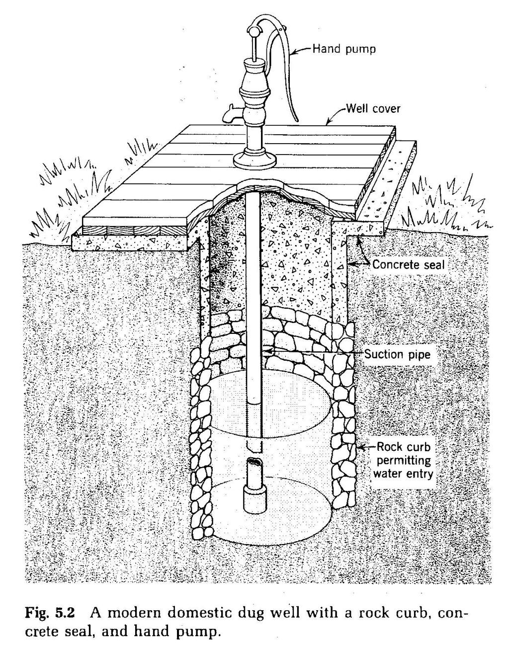
12 A. Drilling Methods of Shallow Wells 1. Dug wells: Depths - 10' to 50' Diameter - 3' to 10' Below W.T. 10' to 20' Yield < 100 gpm (domestic wells) gpm (properly constructed wells)
13
14 Consolidated no casing is required Unconsolidated a rock, brick or concrete curb is required to allow water entry Gravel should be backfilled around the curb and at the bottom of well to control sand entry and possible caving
15 2. Bored Wells: Constructed by earth auger operated by hand or machine Diameter - 6'' to 8'' casing Depth < 50 Best suited to noncaving formations, metal casing rigid gravel packing
16 3. Driven Wells: Series of connected pipes driven by repeated impacts into ground to below W.T. Diameter - 1 ¼ '' to 4'' Depth - < 50' Suction - type pump used to pump GW to GS W.T. depth < 10' - 15' from GS Yield - 20 to 25 gpm
17 A driven well with driving mechanism Low cost, rapidly installed Suitable for formations with no large gravel or rocks
18 4. Jetted Wells: Cutting action of a drawdown - directed jet of water High-velocity jet washed earth away while casing, which is lowered into a hole, conducts water and cuttings up and out of well
19 Diameter - 1 ½ '' to 4'' Depth - < 50' jet cuttings with water Yield small Suited for consolidated materials Because of speed of jetting and portability of equipment, they are useful for exploratory test holes and for well-well-point system
20 Well-point system Purpose to dewater an excavation site for construction Header Pipes Jetted or Driven wells WT
21
22
 Method Equipment")

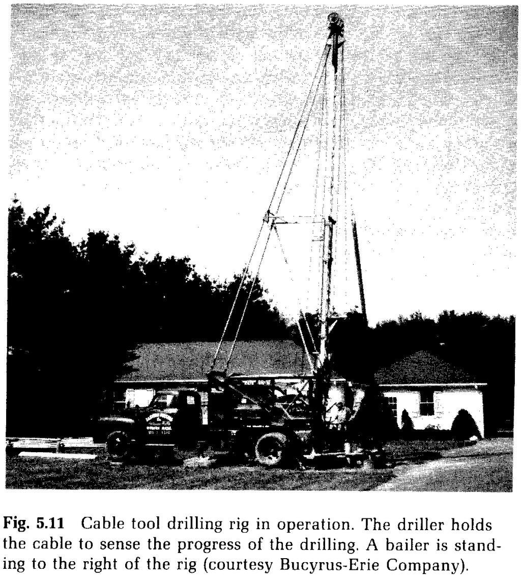
23 B. Drilling Methods for Deep Wells 1. Cable Tool (percussion) Method Equipment includes Well drilling rig mounted on a truck String of percussion tools Bailer Diameter - 2'' to 3'' (6 cm to 80 cm)
24 Suited for consolidated and unconsolidation formations Drilling is done by regular lifting and dropping of the string of tool String of tools rope socket, drilling stem, drilling bit Bailer one way valve Length 10 to 30 Capacity 2 to 90 gal. Bailer
25 During drilling, tools make 40 to 60 strokes/min, ranging from 16'' to 40'' in length Drilling line (rope) is rotated so that bit forms a round hole Additional rope is allowed so that bit forms a round hole Water added in the hole forming a paste, reducing friction on falling bit
26 Casing properly aligned casing 6'' /100 ft deviation from vertical Vertical alignments avoids interference with pump installation and operation Max depth of well = 2000 ft (up to 6000 ft), because wt. of tools bit drive shoe
27
28
29
30
31 2. Hydraulic Rotary Method Rapid method for drilling in unconsolidated formations Diameter up to 18'' Continuous flow of mud in a hollow rotating nit (30 to 60 rpm) Drilllers' mud bentonite clay + water ( gm/cm³ )
32 Material loosened by bit carried up the hole by rising mud (upward vel. = 2 3 fps) No casing ordinarily required because mud forms a clay lining on wall of well, which prevents caving Casing lowered in hole after drilling Washing action is necessary to dilute and take out the clay from hole Calgon (Na hexametaphosphate) with water forced in the casing thru the screen, and up the hole
33 After washing gravel is placed around the casing Ditch or pipe Mud cake Settling pit
34 3. Reverse Rotary Method Limited to unconsolidated formations Diameter < 48'' Use a cutterhead on a rotating bit Water is introduced in the hole
35 Cutting removed by water, pumped by a centrifugal pump. Bit speed 10 to 40 rpm Mixture circulated through a sump in which sand settles, but fine grains recirculated in hole where they aid in stabilizing walls Place casing and clean well by water in casing
36 4. Air Rotary Method Similar to hydraulic rotary method Drilling fluids air, mist, foam, aerated, mud, or other lighter fluids With dry air,upward velocity carrying cutting = fps Drilling speed increased than hydraulic Rotary method
37 Air drilling used in fractured rock When significant GW seeps into hole Air -liquid ratio = 200:1 used Used for consolidated formation Used for hazardous waste test holes
38 WELL COMPLETION 1. Screen and Perforating Field perforation Mills Knife used to produce vertical openings of 0.5'' wide x 5'' long Louver Knife permits openings with width of 1/8'' to 5/32'' Perforated casing louver type shutter type
39 Screen V-shaped blocked less by nearly same size particle than round wire Openings large enough to allow 50%-80% of surrounding grains pass into well A slot size determined from grained-size distribution This passes 50%-80% of aquifer material and should be selected as the coarse remaining fraction forms highly permeable zone around well Well screens used with gravel packs
40 No Clogging Clogging Possible Rods V-shaped Wire
41 2. Gravel Packing Purpose 1) To increase effective well diameter 2) Acts as strainer for fine material 3) Protects the casing from caving used for large-capacity well
42 Gravel thickness = 6'' to 12'' Even small thickness of ½ '' effective in reducing sand movement into well Packs extends 10 ft above screen Perforated size Gravel size Aquifer material
43 3. Length of Screen SL = Q 7.48A0VC SL - optimal length of screen, ft Q - discharge, gpm A0 - effective open area per foot of screen ft² (effective open area = 50% of actual open area) Vc optimal screen entrance vel., fpm (func of perm.)
44 K, gpd/ft² > < 500 gravel alluv alluv fine Vc, fpm
45 4. Well Development Purpose screen 1) Increases well yield finest 2) Prevents sanding 3) Obtains max well life coarsest

46 Methods i. Pumping Pump water starting with low Q and increase it in steps After water clears at maximum Q, pump shut down and water level returns to normal This regular and non-continuous pumping agitates the fines surrounding well
47 They are then pumped out Any coarse sediment in well is bailed out or pumped out by sand pump from bottom Q m c m c m c t

48 ii. Surging Created by rapid up and down motion of plunger Plunger operated above screen Calgon added to well As plunger rises, it draws water into well, while lowering forces water into aquifer At intervals, pump out mud and water Surging continued until sand and mud enter well
49 iii. Use of Compressed Air Air and discharging pipes can be shifted vertically Initially pipes extend to the bottom Water depth is discharging pipe = 2/3 of pipe length 100 to 150 psi developed and air sent in air pipe This causes a powerful surge in well, first increasing and then decreasing as water is forced up the discharge pipe
50 This process loosens fine around screen and brings them in well air water discharging pipe Operation repeated at intervals along screen until sand accretion negligible air pipe

51 iv. Dry Ice First, to loosen clay, Hcl acid is poured in well Casing is capped at top & compressed air is forced in well This forces chemicals into clogged strata Later, cap removed and dry ice added CO2 gas released and builds pressure in well This causes a burst of muddy water from well
52 5. Pumping Equipment Shallow wells Q < 100 gpm Suction lift < 25 ft Motor Water i. Hand pumps ii. Turbine pumps iii. Gear pumps iv. Centrifugal pumps Bowls (impellers) Strainer

53 Deep Wells Q > 100 gpm h > 25 ft i. Plunger pump ii. Deep well turbine pump iii. Displacement turbine pump iv. Air lift pump v. Submersible pump vi. Jet pump Pump Manufacturers furnish advice on size and type of pump
54 6. Maintenance and Repair Good Life 20 years Failure of well decrease in yield causes i. Pump sanding and improper lubrication of motor
55
56 ii. Depletion of water supply iii. Faulty well construction settlement, casing collapse of casing iv. Corrosion due to water Low ph < 7 D.O. < 2 ppm H 2 S > 1 ppm TDS > 1000 ppm CO 2 > 50 ppm Cl 2 > 500 ppm
57 v. Incrustation deposition of minerals on screen If water has high ph > 7.5 Carbonate hardness (CaCO3 ) > 300ppm Iron > 2 ppm Manganese > 1ppm vi. Cleaning Mechanical surging etc. Chemical Hcl, Calgon