R A S C H K A. Compact -Fluidized Bed Incinerator
|
|
|
- Roland Sharp
- 5 years ago
- Views:
Transcription
1 R A S C H K A Compact -Fluidized Bed Incinerator Lonza Engineering Ltd Muenchensteinerstrasse 38,CH-4002 Basel, Switzerland phone: fax: info.engineering@lonza.com website:
2 1 Plant conception The RASCHKA-Compact Fluidized Bed Incinerator (compact FBI) is the core component of a fluidized bed incineration plant for the thermal disposal and utilization directly at site-of sewage sludge and screenings that are produced in smaller wastewater treatment plants. The main components of the incineration plant are the reception-, storing-and conveying sytems for sludge and screenings, the fluidized bed incinerator, the warmwater boiler and the flue gas cleaning (dry system). The realized plant as described below is located in a housing but the plant can be realized as outdoor installation, too. The heat set free by the process is recovered and it is utilized for the process itself and for heating purposes on the wastewater treatment plant. By this heat recovery and utilization fossile fuel is saved and accordingly the production of CO2 is avoided.
3 2 Plant and process description of the compact FBI 2.1 Plant description The compact FBI consists of a welded cylindrical steel casing that has an inner refractory lining and an outer thermal insulation. The FBI consists of the following main sections: Bottom construction with bottom plate Windbox Fluidized bed area Freeboard (postcombustion zone) Incinerator head Heating up combustion chamber The bottom construction with bottom plate serves as basis for the incinerator and for fastening it on the foundation. The bottom construction with bottom plate bears the complete brick lined incinerator and the recuperator (combustion air preaheater) that is located on the flue gas outlet in the incinerator head. All loads and moments resulting from the incinerator are led into the foundation by the bottom construction. The cylindrical windbox is mounted upon the bottom plate. The windbox serves for the distribution of the fluidizing air (main part of the total combustion air) below the nozzle bottom. The heating up combustion chamber is mounted horizontally to the windbox. The heated up fluidizing air flows from the heating up combustion chamber into the windbox. The conical fluidized bed area is mounted upon the windbox. The nozzle bottom that is integrated in the refractory lining separates the fluidized bed area from the wind-box. The nozzle bottom is a ceramic sandwich disc made of a special refractory concrete. The nozzle bottom is equipped with the RASCHKA-air nozzles made from heat resistant cast steel. The fluidizing air is blown through these nozzles. The special shape of the nozzles and their sophisticated arrangement in the nozzle bottom serve for an even distribution of the fluidizing air over the total surface of the nozzle bottom. Three RASCHKA-fuel injection lances are mounted in the fluidized bed area. By means of these lances biogas can be injected directly into the fluidized bed. The biogas is injected during the heating up of the incinerator and for maintaining the incineration process. The RASCHKA-bed material discharge device is located in the fluidized bed area, too. It serves for the discharge of surplus bed material during the operation.
4 The cylindrical freeboard area is mounted upon the fluidized bed area. The flue gases and ash particles coming from the fluidized bed burn out completely in this post combustion zone. The freeboard is mainly equipped with the RASCHA-spreader and the four secondary air injection pipes. The spreader serves for the feeding, the opening up and the even distribution of the combustible. The secondary air injection serves for a perfect temperature profile and air distribution inside the furnace. The special arrangement of the secondary air pipes leads to a rotation and thorough mixing of the flue gas and the secondary air. The conical incinerator head is mounted upon the freeboard. It is equipped with the flue gas outlet socket. The heating up combustion chamber is mounted to the windbox. It is equipped with the combustion chamber burner. The heating up combustion chamber consists of a cylindrical steel casing with the fluidizing air inlet socket, an inner refractory lining and an outer thermal insulation. The fluidizing air is heated up by means of the burner during the heating up process of the incinerator. The windbox, the nozzle bottom, the sand layer upon the nozzle bottom and the whole furnace are heated up by the hot fluidizing air. During the normal operation of the incinerator the fluidizing air is preheated by a gas-gas heat exchanger. The gas-gas heat exchanger (recuperator) is mounted upon the flue gas outlet of the incinerator. The recuperator is heated by the flue gas leaving the incinerator. The temperature of the preheated fluidizing air can be increased on demand by means of the combustion chamber burner. Technical data Fluidized bed incinerator, with ceramic nozzle bottom, stationary atmospheric fluidized bed. Height FBI (from upper end of foundation): ~ 12 m Outer diameter (steel casing freeboard): ~ 3.5 m Space required (floor area): ~ 8 x 10 m Total height incl. Recuperator and air lines: ~ 20 m Firing capacity: 1 MW Max. furnace temperature: 1,000 C
5 2.2 Process description The sewage sludge and the screenings are dewatered mechanically to dry solid contents of 23-30% (sludge) resp. min. 21% (screenings). The screenings are shredded additionally. The mixture of sludge and screenings (combustible) amounts to 1,000 1,300 kg/h. The combustible has a high water content and thus a low heating value. Due to the low heating value the combustion of the mixture is not possible without additional measures: to make it possible that the mixture combusts at 870 C under equilibrated heat balance conditions it is necessary to heat up the combustion air up to 950 C and to feed biogas into the fluidized bed additionally. The main part of the combustion air serves as fluidizing air. The fluidizing air is heated up in two stages. Firstly the fluidizing air is blown by a fan into the recuperator which is heated by the hot flue gas leaving the incinerator. By means of the recuperator the fluidizing air combustion air is preheated up to C. Then the preheated fluidizing air flows into the combustion chamber and is heated further by means of the combustion chamber burner. Then the fluidizing air flows into the wind-box below the nozzle bottom. Then the fluidizing air flows through the nozzles into the fluidizing bed area and fluidizes the sand layer to the fluidized bed. The furnace with refractory lining and sand layer must be heated up to operation temperature before starting the combustible feeding and the incineration process. The heating up combustion chamber with combustion chamber burner (natural gas burner) serves for heating up the furnace. Additionally biogas is injected directly into the fluidzed bed by means of the three fuel injection lances that are mounted in the fluidized bed area. The injection of biogas serves as well for maintaining the combustion process and the minimum furnace temperature of 850 C. As soon as the furnace is heated up to operation temperature the combustible is conveyed evenly and exactly dosed to the spreader. The spreader serves for feeding the combustible into the furnace. The spreader opens up the combustible and distributes it evenly over the surface of the fluidized bed. The incineration process takes place in the evenly fluidized, hot fluidized bed at a temperature of ~ 870 C. The combustible water is evaporated and superheated, the combustible organic substance combusts and the combustible anorganic substance glows out. The controllable secondary air injection in the freeboard area of the incinerator serves for a perfect temperature profile and air distribution inside the furnace. By the special arrangement of the secondary air pipes (downwards and tangentially to the incinerator casing) a rotation and thorough mixing of the flue gas and the secondary air is achieved. The secondary air is a (small) part of the total combustion air. The secondary air is cold air and not heated up opposite to the
6 fluidizing air. The retention time of the flue in the post combustion zone amounts to more than two seconds from the last feeding of combustion air. The fine grain ashes resulting from the combustion leave the incinerator together with the flue gas through the flue gas outlet in the incinerator head. During operation the quantity of the bed material can increase or decrease depending on the characteristics of the combustible. Lack of bed material can be compensated by feeding of silica sand and surplus bed material can be discharged by means of the RASCHKA-bed material discharge device during operation.
7 3 Combustible and process parameters Mechanically dewatered combustible sludge screenings Dry solids (ds)-content % Organic dry solids (ods) content-of % ds Lower heating value (Ihv) of ods MJ/kg Throughput/lay-out, based on the annual throughput of sludge and screenings and a continuous operation of 7,500 hours/year. sludge screenings total Throughput t/y 7,000 9, ,401 9,531 Throughput kg/h 933 1, ,271 Throughput ds t/y 2, ,184 Throughput ds kg/h Throughput water t/y 4,900 7, ,217 7,344 Throughput water kg/h Process parameters based on the incineration at 870 C with feeding of auxiliary fuel (natural gas, biogas), firing capacity ~ 1 MW. lay -out Combustion air mn 3 /h 3,000-3,300 Flue gas 870 C -Flow (wet) --N2 --O2 --CO2 --H2O -Ashes mn 3 /h Vol.-% Vol.-% Vol.-% Vol.-% kg/h 4,000-4,

8 4 pictures General arrangement

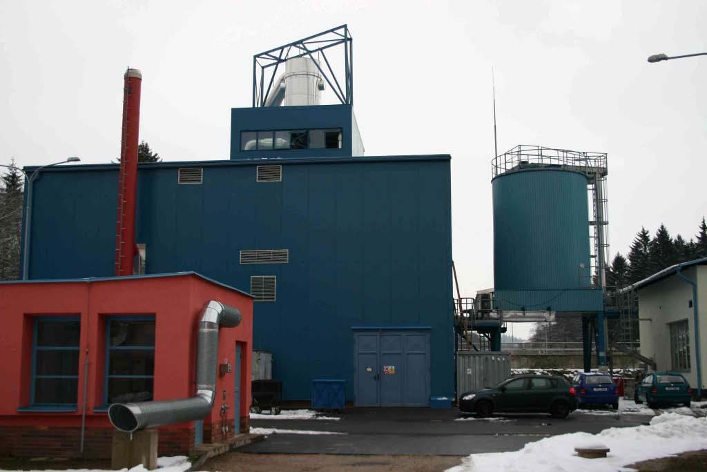
9 Front view of housing Rear view of housing

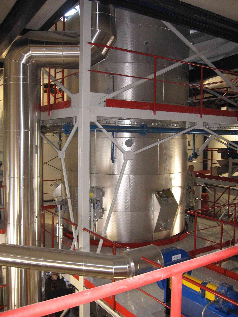
10 Fluidized bed incinerator with heating up combustion chamber


11 Incinerator lower part with heating up combustion chamber Heating up combustion chamber with fluidizing air line and burner air line
12 Freeboard


13 RASCHKA spreader for combustible feeding RASCHKA fuel injection lances for the injection of biogas