Best Practices for Fogging Systems for Capacity & Efficiency Enhancement of Combustion Turbines During Hot Weather
|
|
|
- Ann Carson
- 5 years ago
- Views:
Transcription
1 Best Practices for Fogging Systems for Capacity & Efficiency Enhancement of Combustion Turbines During Hot Weather By Don Shepherd Caldwell Energy Company Sponsored by: Turbine Inlet Cooling Association (TICA) August 19, 2014; 1 PM (U.S. Central Time) Call-In Number: Access Code: #


2 Dharam Punwani President Avalon Consulting, Inc. Executive Director, TICA Don Shepherd Vice President Caldwell Energy Company TICA Board Member
3 Who is TICA? The Turbine Inlet Cooling Association (TICA) promotes the development and exchange of knowledge related to gas turbine inlet cooling The TICA website is one-stop source of TIC technical information, including Installation Database & Performance Calculator TICA is a non-profit organization.

4 TICA Member Benefits Access to full/detailed version of TIC Installation Database Access to full/detailed version of the TIC Technology Performance Calculator GT Users get access to the TIC Forum Suppliers information is included in the Resource Guide on TICA Website, have access to advertisement space on that site, and have opportunity to display literature at the TICA booths at various electric power trade shows Become a Member Today!!!
5 Turbine Inlet Cooling Best Practices Upcoming Webinar Schedule October 8, 2014: Chiller Systems December 12, 2014: Thermal Energy Storage February 11, 2015: Wet Compression April 8, 2015: Hybrid Systems All Webinars start at 1 PM (U.S. Central Time)
6 Agenda: Why Cool Combustion Turbines (CT) Maintenance of Fogging systems Ductwork and array Inspections Various pump skids Best Practices for Using Fogging
7 Unfortunate Fundamental Characteristics of All Combustion Turbine Power Plants During hot weather, just when power demand is at it s peak. 1. CT Total Power output decreases up to 35% below rated capacity (Extent of the decrease depends on the CT design) 2. Efficiency decreases leading to increased fuel consumption (heat rate) and emissions per kwh..up to 15% more fuel consumed (Extent of the decrease depends on the CT design)
8 Why CT Power Output Capacity Decreases with Increase in Ambient Temperature? Power output of a turbine is proportional to the mass flow rate of hot gases from the combustor that enter the turbine Mass flow rate of combustor gases is proportional to the flow rate of the compressed air that enters the combustor Compressors provide compressed air and are volumetric machines, limited by the volumetric flow rate of inlet air they can pull or suck in As ambient temperature increases, the air density decreases. This results in a decrease of the mass air flow rate Reduced mass flow rate of inlet air reduces the mass flow rate of the combustor gases and hence reduced power out put of turbine
9 Why CT Efficiency Decreases with Increase in Ambient Temperature? Compressor of a CT system consumes almost two-third of the turbine s gross output Compressor requirement increases with increase in air temperature Increased power required by the compressor reduces the net electric power available from the CT system
10 % OF RATED POWER Effect of Hot Weather on CT Generation Capacity Depends on CT Design 105% EFFECTS OF COMPRESSOR INLET AIR TEMPERATURE ON GAS TURBINE POWER OUTPUT PERIOD OF GREATEST DEMAND 100% 95% 90% 85% ISO DESIGN POINT NEW AERO-DERIVATIVE POWER OUTPUT Compression Ratio = 30 OLD "FRAME" POWER OUTPUT Compression Ratio = 10 Up to 19% capacity loss at peak demand for this CT 80% COMPRESSOR INLET AIR TEMPERATURE, degrees F
11 Net CT Power Output,% of Design Turbine Inlet Cooling Overcomes the Effects of the CT CharacteristicDuring Hot Weather Rated Capacity No Cooling With TIC Rated Capacity With Cooling No Cooling Ambient Dry-Bulb Temperature, F
12 Maintaining your fogging System Daily Inspections Monthly Inspection Yearly Inspections
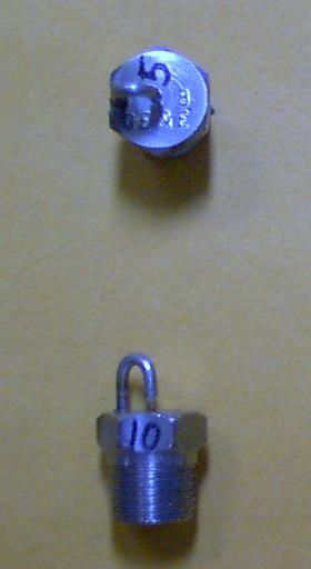
13 Duct work condition Materials of construction Coating systems Drain System Obstructions Demineralized Water Source Control System Integration Nozzles Winterization
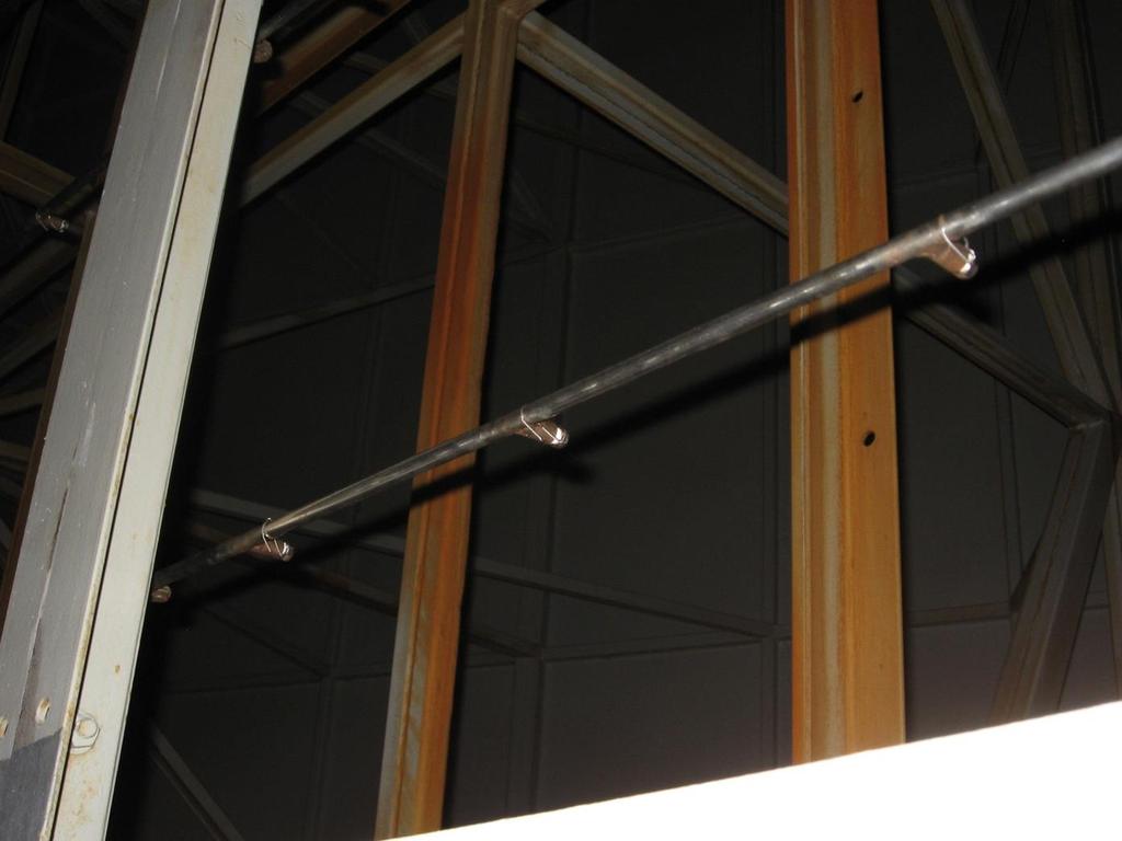
14 Typical Fogging nozzle location Silencing panels

15 Light Uniform Spray pattern is what you are looking for during the inspection
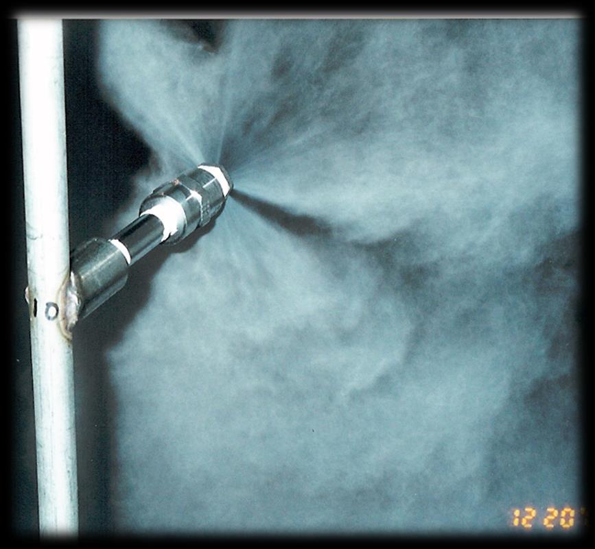
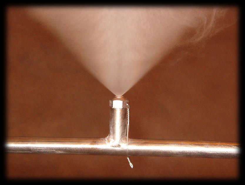
16 Non-uniform spray pattern Uniform spray pattern
17

18 Water coalesces on structural steel - shedding large drops into inlet air stream Water coalescing on vertical structural steel ran to the duct floor. Water puddles in trough created by duct floor and trash screen structural steel
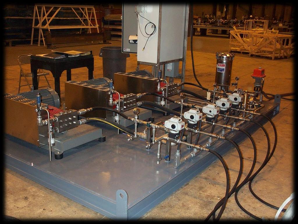
19 Weekly Inspections Pumps operated near design conditions Pump Check Valves Oil added Standard component packaging Excessive vibration, fitting leaks Oil leakage 7 7

20 Monthly Inspection Hoses Suction Filters Pulsation Dampener Oil Leaks Belts Regulators
21 Oil leaks Daily

22 Pulsating Dampener Regulator for system pressure
23 Monthly Inspections for Common discharge manifold systems 1 Discharge Valve Inspection Suction Filter Inspection Seal Inspection Discharge filters inspected
24

25 Direct Drive High pressure filter Quality Instruments

26 Calibrate Instruments yearly Check Filters on Monthly

27 Inspection of pump yearly
28 1. Measure inlet Relative Humidity A. GT s that are prone to blade issues B. System Efficiency 2. Change to a common manifold A. High reliability B. Can add redundancy in pumping 3. Inspections A. Fogger Skid B. Arrays and duct work C. Amount of Water being drained away D. Quality of Demineralized water 4. Winterization of system 5. Add quality instrumentation ie. Rosemount, Siemens, etc.
29 6. Add discharge filtration 7. Change to oil less design pump 8. Treat system as a revenue generator!


30 Advantages With Nessie High Pressure Water Pumps PAH/PAHG /90 Axial piston pump: Based upon well know principle from oil hydraulics. Swash plate type with fixed displacement. Various displacements in same frame. High efficiency Compact design Oil-less design 160 Bar Continuous pressure AISI 316 Stainless Steel Housing
31 Thank You! If You are not a TICA Member, Please consider Joining TICA Now!