Ⅰ Outline of the Plant
|
|
|
- Barry Watson
- 5 years ago
- Views:
Transcription

1
2 Rokkasho Reprocessing Plant is first commercial plant in Japan,adopting the technology developed on the basis of more than 40years of operation results in both France and United Kingdom, as well as operating experience gained by Atomic Energy Agency (JAEA). Contents Ⅰ Ⅱ Ⅲ Ⅳ Ⅴ 1


3 Ⅰ Outline of the Plant Schedule Mar. 1989:Applied license for the reprocessing business Dec. 1992:Approval was granted on the reprocessing business Apr. 1993:Staeted construction The first half of FY2018:Commissioning 18t 2007 Rokkasho Reprocessing Plant 2
4 Ⅱ Nuclear Fuel Cycle and Reprocessing Plants in the World Nuclear Fuel Cycle Uranium Mine Refining Plant Conversion Plant Recovered Uranium Uranium Hexafluoride Uranium Enrichment Plant Reprocessing Plant Vitrified Waste Storage Center Spent Fuel High Level Radioactive Waste Recycle Fuel Stock Center Recovered Uranium and Plutonium MOX Fuel MOX Fuel Fabrication Plant Uranium Dioxide Enriched Uranium Hexafluoride Reconversion Plant Uranium Dioxide Fabrication Plant Underground Storage Facility Spent Fuel Nuclear Power Plant Low Level Radioactive Waste Fuel Assembly Low-Level Radioactive Waste Disposal Center 3
5 The Composition of Uranium Fuel for Light Water Reacter and MOX Fuel 4
6 Ⅲ Reprocessing Plant Process Outline 5
7 Specifications of Spent Fuel to be Reprocessed 6


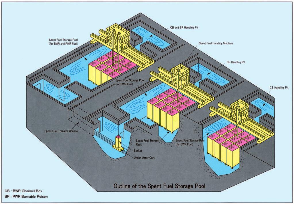
8 Receiving and Storage of Spent Fuel 7

9 Specification 8


10 Shearing and Dissolution From the Spent Fuel Receiving and Storage Process Main Equipmemts 9
 Sheared Fuel Pieces Outlet(To Sheared Fuel Pieces Chute) Magazine Spent Fuel Assembly Fuel Inlet Outline of Shearing")
11 Shearing-Blade Drive Cylinder Main Fuel-Holder Drive Cylinder uxiliary Fuei-Holder Drive Cylinder Shearing-Blade Holder Lid Body Fuel Feeder End Piece Outlet Hopper (To End Piece Chute) Sheared Fuel Pieces Outlet(To Sheared Fuel Pieces Chute) Magazine Spent Fuel Assembly Fuel Inlet Outline of Shearing Machine 10
 Diluent (normaldodecane) Diluent (normaldodecane) Diluent(normaldodecane) Diluent (normaldodecane)")

12 Separation Nitric Acid (HNO 3 ) Nitric Acid (HNO 3 ) Nitric Acid (HNO 3 ) Nitric Acid (HNO 3 ) Nitric Acid (HNO 3 ) Diluent (normaldodecane) Diluent (normaldodecane) Diluent(normaldodecane) Diluent (normaldodecane) Main Equipments Separation Facility extracts "uranium and plutonium" from the dissolved solution sent from the dissolution process. And the second Facility separates "uranium" and "plutonium". normaldodecane normaldodecane 11


13 Neutron Absorber(Boron-iaced Concrete) Water Phase (Nitric Acid Solution) Inlet 12
14 Purification Diluent(normaldodecane) Diluent(normaldodecane) Diluent(normaldodecane) From the Uranium-plutonium Co-denitration Facility Diluent (normaldodecane) 13


15 Main Equipments As a result, impurities in the organic solvent containing plutonium will be rebuced. normaldodecane 14


16 Denitration and Product Storage Seal Vessel 主な仕様 15
. For microwave heating, the same frequency is used as microwave oven for home use.")

17 Off Gas Outlet Blowback Air Inlet Candle Filter * :Fluidized-bed is a state in which particles behave as liquid, when small particles filled in a container are blown with gas from the bottom (UO3 particles in the case of Uranium Denitration Facility). For microwave heating, the same frequency is used as microwave oven for home use. Body Microwave Generator Microwave Leader Electric Heater Seed Powder Inlet Body Spray Nozzle Molten Salt Outlet UO3 Powder Outlet Internal Heater Tubes Denitration Dish Mixed Solution Molten Salt Inlet Fluidizing Ari Inlet Underflow Nozzle Outline of the Denitration Column In the Denitration Column that is installed in the Uranium Denitration Facility, air is supplied from the lower part of the column to form the fluidized bed of the UO3 powder. The uranyl nitrate solution is sprayed into this fluidized bed from spray nozzles with air, and electric heaters thermally decompose the solution at approximately 300. Turn-Table Outline of the Denitrator In the Denitrator that is installed in the Uraniumplutonium Co-denitration Facility, the mixed solution of the plutonium nitrate solution and the uranyl nitrate solution is surprised into the Denitration Dish, then concentrated and denitrated by microwave. 16

18 Recovery of Acid and Solvent Recovered Nitric Acid(To be Reused) To the Separation Process, Purification Process,etc. No.2 Acid Recovery System Recovered Solvent (To be Reused) normaldodecane Main Equipments 17

")
/stage Iodine Filter : 12 sets(composed of 2 stages) Iodine elimination efficiency : more than 99.")

19 Gaseous Waste From the Shearing Machine, Dissolver,lodine Desorder,etc. From the Plutonium Concentraton Feed Vessel, etc. in the Purification Process 1st Oxidation Columu,etc. in the Purification Process NOx Scrubbing Column Heater, Iodine Filter,etc. To the Main Stack Shearing Off Gas and Dissolution Off Gas Treatment Facility HEPA Filter : 6 sets(composed of 2 stages) Particle elimination efficiency : more than 99.9%(0.3μmDOP particle)/stage Iodine Filter : 12 sets(composed of 2 stages) Iodine elimination efficiency : more than 99.6% Main Equipments Vessel Off Gas Treatment Facility HEPA Filter Particle elimination efficiency : more than 99.9%(0.3μmDOP particle)/stage Iodine Filter Iodine elimination efficiency : more than 90% HALW Vitrification Off Gas Treatment Facility HEPA Filter Column type : 4 sets(composed of 2 stages) Box type : 2 sets Particle elimination efficiency : more than 99.9%(0.3μmDOP particle)/stage Iodine Filter : 2 sets Iodine elimination efficiency : more than 90% 18

20 Liquid Waste (Low Active Liquid Waste (LALW)) Concentrated LALW Storage Vessel Main Equipments 19


21 Liquid Waste (High Active Liquid Waste (HALW)) Main Equipments 20

22 Solid Waste 21
23 In the Virtification Melter, electric current passes directly through the glass by using electrode installed in the furnace, and it melts by the generating heat of Joule. The molten glass in a Vitrification Melter is poured into the canister by heating the flow-down nozzle located at the lower part of casing. 22


24 Central Control Room Analysis Facility 23


25 Ⅳ Safety Measures trays. Schem of Multiple Protection against Leakage 24
26 25


27 ⅤCenter For Research & Development 26
28 JAPAN NUCLEAR FUEL LIMITED