Small Modular Reactors UK Energy System Requirements For Cogeneration
|
|
|
- Ashley Booker
- 5 years ago
- Views:
Transcription

1 Small Modular Reactors UK Energy System Requirements For Cogeneration Mike Middleton Energy Technologies Institute 5 th SMR Summit Charlotte 14 th & 15 th April Energy Technologies Institute LLP The information in this document is the property of Energy Technologies Institute LLP and may not be copied or communicated to a third party, or used for any purpose other than that for which it is supplied without the express written consent of Energy Technologies Institute LLP This information Energy is given Technologies in good faith based Institute upon the latest LLP information - Subject available to to notes Energy on Technologies page 1Institute LLP, no warranty or representation is given concerning such information, which must not be taken as establishing any contractual or other commitment binding upon Energy Technologies Institute LLP or any of its subsidiary or associated companies.
2 Presentation Structure Introduction to the ETI Potential role for nuclear in a UK low carbon 2050 energy system Finding a niche for small nuclear in a 2050 UK low carbon energy system Current ETI projects & Interfaces Provisional Conclusions Alternative Nuclear Technologies Study Provisional Conclusions ESME Sensitivity Analysis For Nuclear Next Steps Likely ETI Conclusions

 is a public-private")


3 Introduction to the ETI organisation The Energy Technologies Institute (ETI) is a public-private partnership between global industries and UK Government ETI members Delivering... Targeted development, demonstration and de-risking of new technologies for affordable and secure energy Shared risk ETI programme associate 2.
4 What does the ETI do? System level strategic planning Technology development & demonstration Delivering knowledge & innovation 3.
5 ETI Invests in projects at 3 levels Knowledge Building Projects typically... up to 5m, Up to 2 years Technology Development projects typically m, 2-4 years TRL 3-5 Technology Demonstration projects Large projects delivered primarily by large companies, system integration focus typically m+, 3-5 years TRL

6 Typical ESME Outputs
7 Mt CO 2 /year Net UK CO 2 Emissions Typical ETI Transition Scenario International Aviation & Shipping Transport Sector Buildings Sector Power Sector Industry Sector Biocredits Process & other CO (Historic) Notes: Usual sequence in the least-cost system design is for the power sector to decarbonise first, followed by heat and then transport sectors Biocredits includes some pure accounting measures, as well as genuine negative emissions from biomass CCS DB v3.4 / Optimiser v3.4
8 2050 UK system cost 2010 /Te CO first appearances of major technologies, in order of increasing effective carbon price > 300/Te or >$480/Te Energy storage and distribution Efficiency improvement Nuclear Appliances, heating, buildings, vehicles, industry Offshore Wind Light vehicles (fuel cell / electrification) 0 0% 10% 20% 30% 40% 50% 60% 70% 80% 90% 100% UK Energy System CO2 Reduction UK legal (including aviation and shipping) target (2050) CCS Marine
9 The Role For Nuclear Within A UK Low Carbon Energy System Proven Low carbon Baseload electricity Choice For ranges of LCOE For ranges of CO 2 abatement To Maximum Cap of 40GW For nearly all scenarios LCOE Levelised Cost Of Energy
10 GW Installed Electrical Generation Capacity Typical Scenario DB v3.4 / Optimiser v (Historic) Geothermal Plant Wave Power Tidal Stream Hydro Power Micro Solar PV Large Scale Ground Mounted Solar PV Onshore Wind Offshore Wind H2 Turbine Anaerobic Digestion CHP Plant Energy from Waste IGCC Biomass with CCS Biomass Fired Generation Nuclear CCGT with CCS CCGT IGCC Coal with CCS PC Coal Gas Macro CHP Oil Fired Generation Interconnectors Notes: Nuclear a key base load power technology. Almost always deployed to maximum (40GW) Big increase in 2040s is partly due to increased demand (for heating and transport), and partly because the additional renewables need backup
11 TWh Annual Electricity Generation Typical Scenario (Historic) DB v3.4 / Optimiser v3.4 Geothermal Plant Wave Power Tidal Stream Hydro Power Micro Solar PV Large Scale Ground Mounted Solar PV Onshore Wind Offshore Wind H2 Turbine Anaerobic Digestion CHP Plant Energy from Waste IGCC Biomass with CCS Biomass Fired Generation Nuclear CCGT with CCS CCGT IGCC Coal with CCS PC Coal Gas Macro CHP Oil Fired Generation Interconnectors Notes: Nuclear used as base load CCGT CCS does more load following, both summer/winter and within day
12 Can Small Nuclear Build A Niche Within The UK Energy System? For SMRs to be deployed in UK: technology development to be completed range of approvals and consents to be secured sufficient public acceptance of technology deployment at expected locations against either knowledge or ignorance of alternatives deployment economically attractive to o reactor vendors o utilities and investors o consumers & taxpayers Small Nuclear Large Nuclear FID Final Investment Decision Realistic objective for SMRs to be economically attractive to all stakeholders
13 Niche For Small Nuclear In The UK Technology Mix? Single Revenue Stream Multiple Revenue Streams Containment structure 1. Baseload Electricity Containment structure 1. Baseload Electricity 2. Variable Electricity To Aid Grid Balancing Control rods Steam Generator Generator Control rods Steam Generator Generator Turbine Turbine Reactor vessel Condenser Waste Heat Rejected To The Environment Reactor vessel Condenser 3. Waste Heat Recovery To Energise District Heating Systems
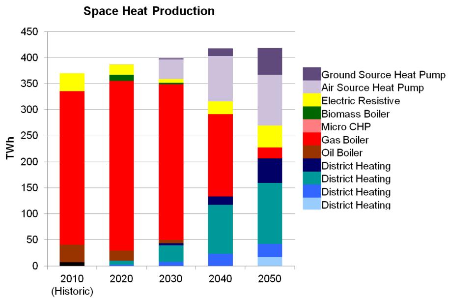
14 Mt CO 2 /year Net UK CO 2 Emissions Decarbonising Heat Is Important International Aviation & Shipping Transport Sector Buildings Sector Power Sector Industry Sector Biocredits Process & other CO (Historic) Notes: Usual sequence in the least-cost system design is for the power sector to decarbonise first, followed by heat and then transport sectors Biocredits includes some pure accounting measures, as well as genuine negative emissions from biomass CCS DB v3.4 / Optimiser v3.4

15 Heat / Electricity (GW) Heat demand variability in 2010 Unattractive to electrify it all Heat Electricity Design point for a GB heat delivery system 150 Heat demand Electricity demand Design point for a GB electricity delivery system 0 Jan 10 Apr 10 July 10 Oct 10 GB 2010 heat and electricity hourly demand variability - commercial & domestic buildings R. Sansom, Imperial College
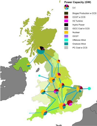
16 ETI Projects Delivered Power Plant Siting Study Explore UK capacity for new nuclear based on siting constraints Consider competition for development sites between nuclear and thermal with CCS Undertake a range of related sensitivity studies Identify potential capacity for small nuclear based on existing constraints and using sites unsuitable for large nuclear Project schedule June 2014 to Dec 2014 Delivered by Atkins for ETI through competitive open procurement process System Requirements For Alternative Nuclear Technologies Develop a high level functional requirement specification for a black box power plant for baseload electricity heat to energise district heating systems, and further flexible electricity to aid grid balancing Develop high level business case with development costs, unit costs and unit revenues necessary for deployment to be attractive to utilities and investors Project schedule August 2014 to Dec 2014 Delivered by Mott MacDonald for ETI through competitive open procurement process ETI scenario analysis to determine attractiveness of such black box to UK low carbon energy system
17 So What Have We Learned So Far? System Requirements For Alternative Nuclear Technologies ETI ESME Sensitivity Studies For Nuclear incorporating the Power Plant Siting Study Provisional Results Subject to change
 reduced baseload power with extra storage & surge capacity Combined Heat & Power (CHP) plant As above but with heat As above but with heat As above but with")
18 Alternative Nuclear Technologies Project - Results Representative SMR service offerings Baseload Flexible Extra-flex Electricity only SMR power plant Baseload power (runs continuously) Operated in loadfollowing mode (Slightly) reduced baseload power with extra storage & surge capacity Combined Heat & Power (CHP) plant As above but with heat As above but with heat As above but with heat
19 wwwwww CHP mostly waste heat Superheated steam Steam Turbine Generator Electricity Tap off high quality steam to raise grade of DH, but steals power Low grade steam ( waste heat ) Main heat exchanger Heat to DH Network Feed water pump Condenser Cooling water
20 Extra-flex example (30% boost) MWe rating 120 MWe 100 MWe 93 MWe Issues: Bar-to-bar efficiency CAPEX uplift Speed of response Power profile Peak generating rating, 120 MWe 20% boost Surge Power Diurnal load following Balance intermittent renewables Targeting peak prices Boost Energy discharge 120% nominal 100% nominal 93% nominal SMR reactor Rating, 100MWe Energy charge 120 MWh storage Energy charge Hours

21 Future Heat Networks? Almost 50 GB urban conurbations with sufficient heat load to support SMR energised heat networks Heat networks in England and Wales would theoretically require 22 GWe CHP SMR capacity operating at 40% annual capacity factor for heat Provisional Results Subject to change
22 Installed Capacity (GWe) SMR Deployment Schedule To Decarbonise Heat From 2030 to 2045 Provisional Results Subject to change Low SMR build rate 4 x 100MWe Mid SMR build rate 4 x 100MWe High SMR build rate 4 x 100MWe

23 ANT Project - Economic model
24 Caveat High uncertainty Many assumptions Multi-decadal timescale Treat results with caution Indicative only Provisional Results Subject to change
25 Stepped cost reduction pathway Specific CAPEX / LOCE FOAK First iteration Factory built modules NOAK years Cost reduction within factory setting 2nd Factory Time Provisional Results Subject to change
26 Specific CAPEX: /kw Target CAPEX: Baseload electricity SMR ~ 10,000/kW FOAK N O A K ~ /kW 10% investor hurdle rate Breakeven CAPEX ~ 4000/kW ~ /kW 1st Factory 10 years at 10x100MW 2 nd Factory 10 years at 20x100MW 5GW 20GW Cumulative deployment (not to scale) Provisional Results Subject to change
27 Internal Rates of Return (IRR) From The Model 18% 16% 14% 12% 10% 8% 6% F O A K N O A K 4% 2% 0% Elec baseload Elec flex Extraflex CHP baseload CHP flex CHP Extra- flex Provisional Results Subject to change
28 Specific capex: /kw Target CAPEX: CHP SMR 8,000 Breakeven capex for NOAK CHP plant 7,000 6,000 5,000 4,000 3,000 2,000 1, % 30% 20% Annual capacity factor of heat Projected 1 st factory NOAK costs 85/MWh 60/MWh 40/MWh Does not include heat network costs (except connecting mains) Provisional Results Subject to change
29 LCOE: /MWh Cost reduction drivers 30% 28% 10% 4% 15% 40-60% FOAK 1x100MW Factory Production Provisional Results Subject to change Learning Multiple units (x4) Early power Lower WACC Heat Value
30 ESME Energy System Model - Sensitivity Analysis For Nuclear Approach Legacy nuclear capacity identified Large nuclear siting capacity and location constraints applied Single Generation IV plant added as 1200 MWe capacity from 2045 Each of the 3 following variants tested in turn using ANT Project costings: Baseload electricity SMRs at locations identified - ESME CHP SMRs at locations identified - ESME Extraflex CHP SMRs at locations identified - ESME
31 Follow On Work From December 2014 Power Plant Siting Study Phase 2 Address known area of underestimate for large nuclear capacity access to river flow data successfully negotiated Energise ANT heatworks with SMR site capacity twice-over Respond to peer review System Requirements For Alternative Nuclear Technologies Phase 2 Incorporate additional SMR sites from PPSS to energise heat networks Consider options and implications of future DH system design and potential impacts on SMR CHP economics Consider the range of plant operating modes Consider deployment, operating and financing issues relevant to SMRs Respond to peer review 5 overlapping peer reviews commissioned; each in 3 stages ESME Sensitivity Studies For Nuclear using PPSS & ANT Phase 2 Results
32 ETI Likely Conclusions Regarding Cogeneration With SMRs SMRs offer additional electricity generating capacity but with uncertainty regarding costs and their status as a key technology in lowest cost transition to 2050 CO 2 abatement compliance Likely SMR CHP niche in UK markets 2030 to 2045; energising large low carbon DH systems: Heat is valuable in a low carbon energy system Low thermal efficiency & operating costs make SMRs financially attractive for CHP Flexible siting allows SMRs to energise DH systems that other technologies cannot reach Timing and location of developing low carbon heat markets suggests large Gen III+ for early low carbon baseload power, combined with a later dispersed Fleet of SMRs delivering CHP An energy mix with more nuclear and more intermittent renewables makes energy system balancing more challenging; flexible/extraflex SMRs are likely to be more valuable to the system Greatest barrier to UK SMR deployment is not technology or economics but public acceptability Work yet to complete and is subject to Peer Review To Be Disseminated Autumn 2015
33 Registered Office Energy Technologies Institute Holywell Building Holywell Park Loughborough LE11 3UZ For all general enquiries telephone the ETI on For more information about the ETI visit For the latest ETI news and announcements The ETI can also be followed on