Transfer and Storage of Flammable Liquefied Hydrocarbon Gases
|
|
|
- Amberly Roberts
- 5 years ago
- Views:
Transcription
1 Transfer and Storage of Flammable Liquefied Hydrocarbon Gases GPA Technical Meeting Antwerp, Belgium February, 2012 Moving Fluids - Developments in Machinery Joel V. Madison CEO & President Ebara International Corporation
2 1. Hydrocarbon Fluids 2. LNG Supply Chain 3. Challenges in Fluid Handling 4. Submerged Motor Pump Design 5. Future Developments
3 1. Hydrocarbon Fluids
4 Cryogenic fluids are characterized by very low boiling temperatures Saturation temperature is dependent on storage pressure Gas to liquid ratio is ~600:1, making transportation in liquid form the most economical
5 Methane (-162 C, -258 F) Ethane (-89 C, -128 F) Propane (-42 C, -44 F) Butane (+0.6 C, +33 F) Nitrogen (-196 C, -320 F) Ethylene (-104 C, -155 F) Propylene (-48 C, -54 F) Ammonia (-33 C, -28 F)
6 2. LNG Supply Chain

7 Liquefaction Transportation Regasification


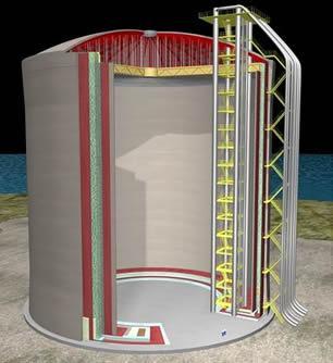
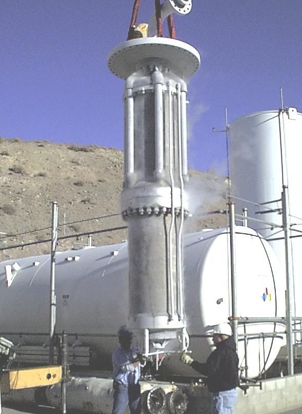
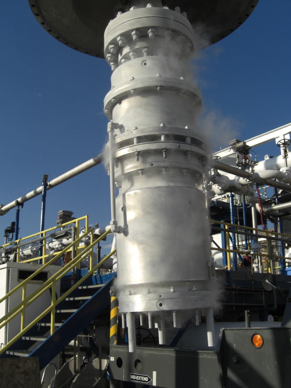
8 VESSEL MOUNTED PUMPS RETRACTABLE IN-TANK PUMPS

9 4/18/2012

10 LIQUID EXPANDERS


11 MARINE CARGO & SPRAY PUMPS

12

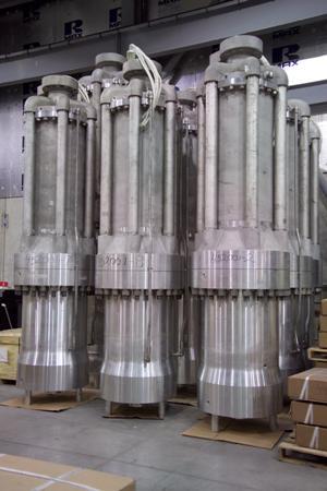
13 RETRACTABLE IN-TANK PUMPS HIGH PRESSURE SEND OUT PUMPS 4/18/2012
14 4/18/2012
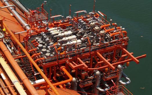
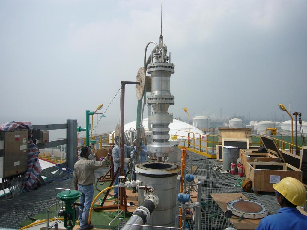
15 Floating Storage and Regasification Units (FSRU) and Floating Production Storage and Offloading (FPSO) are the latest developments in the LNG supply chain


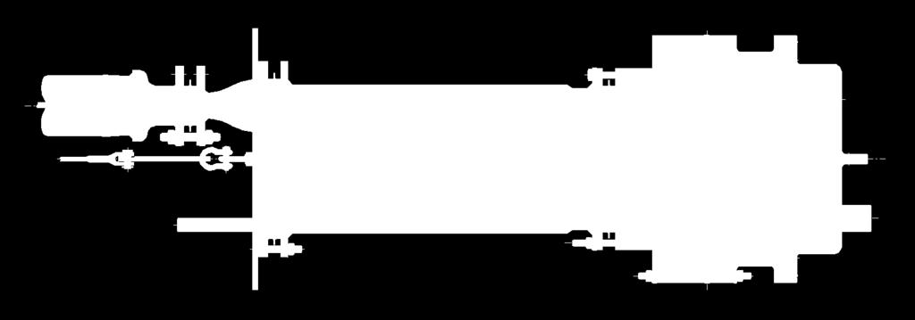
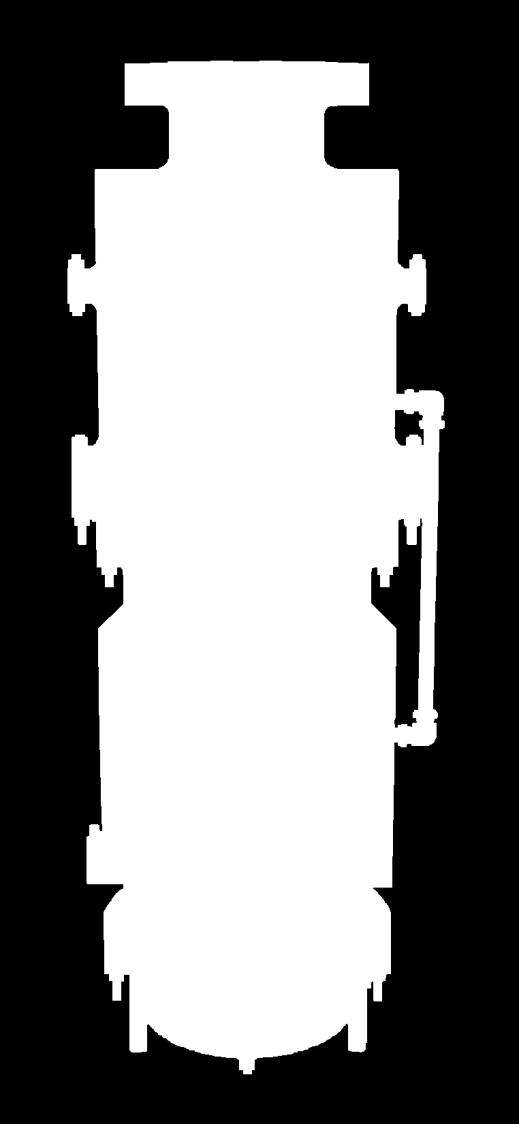
16 HIGH PRESSURE SEND OUT PUMPS

17 LIQUID EXPANDERS
18 3. Challenges in Fluid Handling

19 Extremely low temperatures require precise selection of materials and their manufacturing processes

20 Low viscosity fluids impact bearing selection and design

21 Flammable liquids require external electrical components be installed in a hazardous area
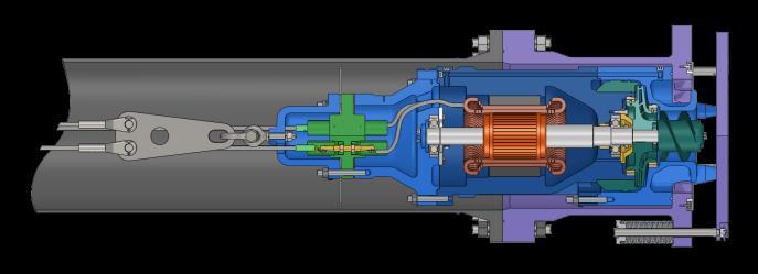
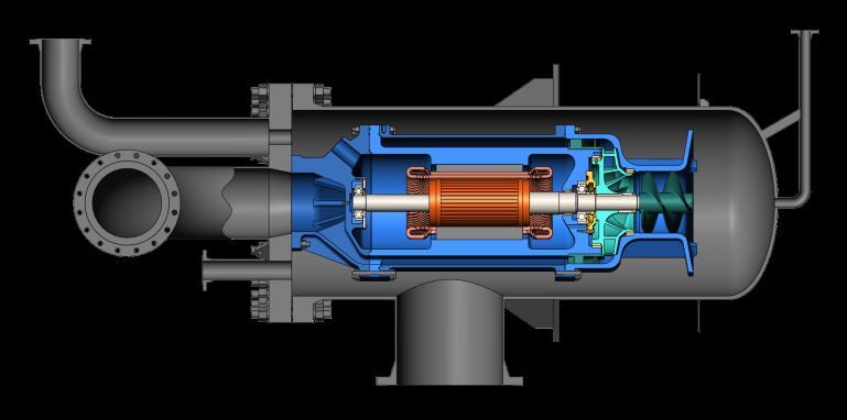
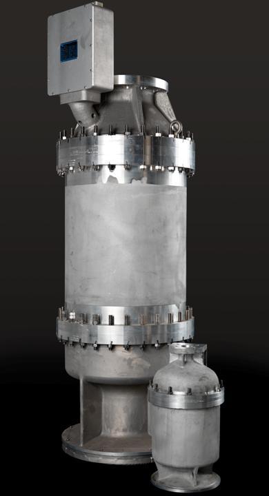
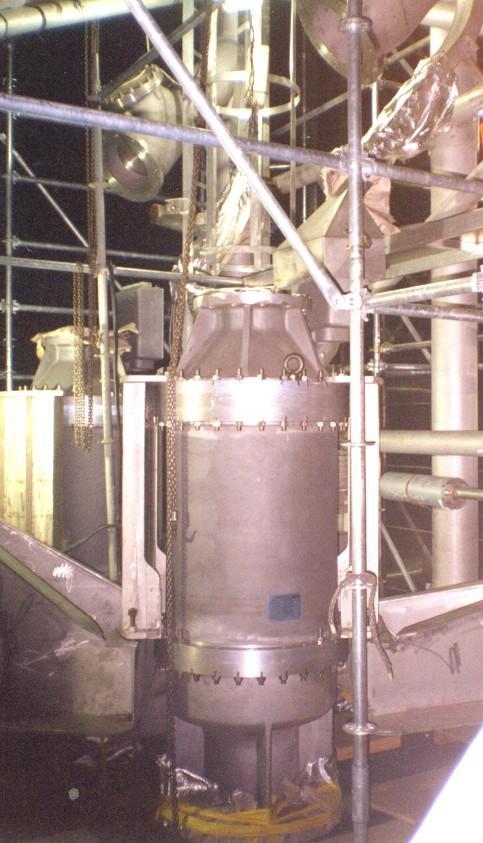
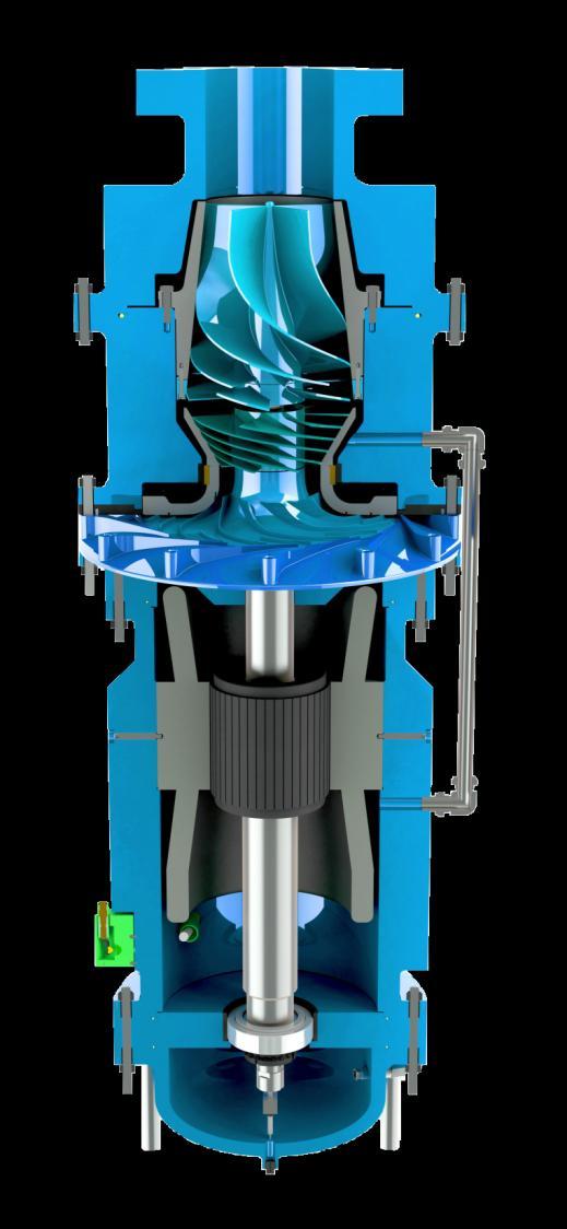
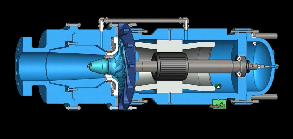
22 4. Submerged Motor Pump Design
23 With a conventional external motor, pumps for hazardous duties present risks due to their design: Shaft seals may leak into the atmosphere Couplings may lead to misalignment The motor must be installed in an explosionproof housing
24 Advantages of a submerged motor design: Elimination of shaft seals No alignment problems Compact size No bearing lubrication system required Reduced noise Explosion-proof motor not required
25 Materials: Sand cast aluminum AA T6, 6061 Stainless steel 15-5 PH and 304 Bronze C93200 Ceramic Si 3 N 4 Good ductility at low temperatures Stable, good magnetic properties Proper hardness and wear characteristic at low temperatures Improved wear and electrical insulation

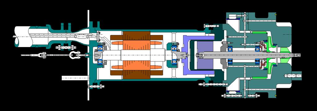
26 Submerged motor: Wet design Windings are completely submerged in liquid Hydrocarbons are a dielectric fluid Motor is cooled by product, allowing for a compact design Installed on a common shaft with the pump
27 Dual-seal power cable feedthrus isolate the submerged electrical components


28 Dual-seal power cable feedthrus isolate the submerged electrical components N 2


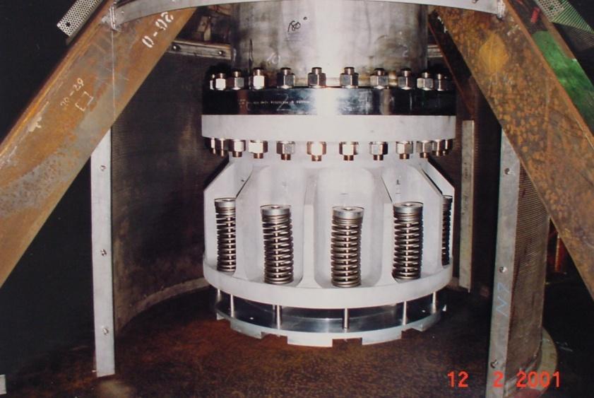
29 Axial thrust balancing: Thrust bearings are not suitable for low viscosity fluids Deep groove radial ball bearings require a hydraulic method to balance thrust loads Most widely used method is the TEM (Thrust Equalizing Mechanism)
30 TEM (Thrust Equalizing Mechanism)
31 TEM (Thrust Equalizing Mechanism)
32 FIXED ORIFICE VARIABLE ORIFICE TEM (Thrust Equalizing Mechanism)

33 TEM (Thrust Equalizing Mechanism)
34 Some cryogenic liquids are corrosive to the materials used in electric motors e.g. Ammonia (-33 C, -28 F) The submerged motor can be isolated from the liquid by means of a magnetic coupling
35
36 Submerged cryogenic pump technology has been applied to other machines Cryogenic liquid expanders replace a Joule-Tompson valve and can increase LNG production by 3-5%
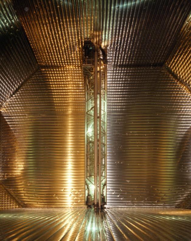
37 In the LNG liquefaction process, expanders are placed in the LNG production stream and the refrigerant loop

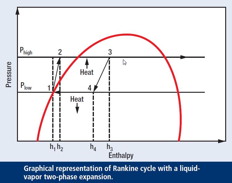
38 Expanders reduce the enthalpy of the liquid in a near isentropic expansion The resulting energy is exported as electrical energy via a generator
39 A submerged generator design allows for operation in the two-phase liquid-vapor region Two-phase expanders combine a liquid expander and flashing valve into one machine for increased LNG production
40 Pressure P 1 Saturated Curve P 2 P 3 Joule Thomson Valve Single Phase Expander Two Phase Expander w/jet Exducer Two Phase Expander w/condensation Cone Enthalpy
41
42 5. Future Developments

43 Hydrostatic bearings eliminate the rotating elements Pressurized liquid is used to provide radial stiffness and damping
44 LNG Regasification Process LNG is stored at receiving terminals in insulated tanks at atmospheric pressure and a temperature of 111 Kelvin For regasification and distribution the LNG is pumped to high pressure and then heated to vaporize into its gaseous state
45 Power Recovery from LNG Regasification LNG regasification plants are large heat sinks and require large heat sources The temperature difference of 170 C between the heat source and the heat sink provides the pre-condition for an efficient power recovery
46

47 1 2 Pump 2 3 Heat input 3 4 Expansion 4 1 Condensation cooling


48 The proposed working fluid is LPG The LPG is passed through two separate heat exchangers and a single machine which combines a pump and a two-phase expander
49 Thank You