Solar Cracking and Solar Reforming
|
|
|
- Elaine Baldwin
- 5 years ago
- Views:
Transcription

1 Chart 1 Solar Cracking and Solar Reforming Dr. Christian Sattler christian.sattler@dlr.de
 Gasification (see Dr.")
2 Chart 2 Established High Temperature Industrial Processes Cracking of natural gas to produce -Hydrogen -Carbon black Goal: Two valuable products, easy storable solid (really?) Gasification (see Dr. Meiers talk) and reforming of carbonaceous feedstock for the production of synthesis gas -Natural gas -Coal -Petcoke -Waste -Biomass Goal: Fuels with reduced CO 2 emissions for power production but also for air, land, and, sea transportation Roof-fired industrial reformer


, CERTH/CPERI (EL), DLR (DE), TIMCAL")
3 H 2 -Production by Solar Cracking of Hydrocarbons Decarbonisation of Methane CH 4 C + 2H 2 Temperature up to 1600 C Ambient pressure. Conversion 70%. Theoratical system efficiency: 30% EU Project SOLHYCARB Source: Hirsch et al. Partner CNRS/PROMES (FR) - ETH, PSI (CH), WIS (IL), CERTH/CPERI (EL), DLR (DE), TIMCAL (BE), SOLUCAR (SP), CREED (FR), N-GHY (FR)
4 Chart 4 CO 2 Reduction by solar heating of state of the art processes like steam methane reforming and coal gasification CG 20 kg/kg 15 SMR CO 2 Reduction 20 50% SPCR 10 SSMR 5 0 SMR SSMR CG SPCR
5 Chart 5 Steam and CO 2 -Reforming of Natural Gas Steam reforming: H 2 O + CH 4 3 H CO CO 2 Reforming (Dry): CO 2 + CH 4 2 H CO Reforming of mixtures of CO 2 /H 2 O is possible and common Use of syngasfor methanol production: e.g. 2H 2 + CO CH 3 COH (Methanol) Both technologies can be driven by solar energy as shown in the projects: CAESAR, ASTERIX, SOLASYS, SOLREF
6 Chart 6 Solar Methane Reforming Technologies decoupled/allothermal indirect (tube reactor) Integrated, direct, volumetric - Reformer heated externally (700 to 850 C) - Optional heat storage (up to 24/7) - E.g. ASTERIX project - Irradiated reformer tubes (up to 850 C), temperature gradient - Approx. 70 % Reformer-h - Development: Australia, Japan; Research in Germany and Israel Source: DLR - Catalytic active direct irradiated absorber - Approx. 90 % Reformer-h - High solar flux, works only by direct solar radiation - DLR coordinated projects: SOLASYS, SOLREF; Research in Israel, Japan


7 Chart 7 SANDIA-WIS s sodium reflux heat pipe solar receiver-reformer ( ) (b)

 -Convective heated tube")
8 Chart 8 ASTERIX: Allothermal Steam Reforming of Methan -DLR, Steinmüller, CIEMAT -180 kw plant at the Plataforma Solar de Almería, Spain (1990) -Convective heated tube cracker as reformer -Tubular receiver for air heating

9 Chart 9 Pilot Scale Solar Chemical Reactors - SolarGas Experimental set-up of the 200 kw SolarGas reactor Top view of DCORE reactor (right) layout of entire integrated reformer and HRU Source: R. McNaughton et al., CSIRO, Australia
 - Pressurised solar receiver, - Developed by DLR - Tested at the Weizmann Institute of Science, Israel - Power coupled")
10 Chart 10 Direct heated volumetric receivers: SOLASYS, SOLREF (EU FP4, FP6) - Pressurised solar receiver, - Developed by DLR - Tested at the Weizmann Institute of Science, Israel - Power coupled into the process gas: 220 kw th and 400 kw th - Reforming temperature: between 765 C and 1000 C - Pressure: SOLASYS 9 bar, SOLREF 15 bar - Methane Conversion: max. 78 % (= theor. balance) - DLR (D), WIS (IL), ETH (CH), Johnson Matthey (UK), APTL (GR), HYGEAR (NL), SHAP (I)
![Central Receiver Plants: Pressurized air receiver -800 -[ C] -Receiver heat transfer fluid: -Air](/docs-images/86/93454981/images/11-0.jpg "(10-16 bar) -700-600 -960 C -Hybrid system: -The maximum temperature acievable in solar operation is")

11 Central Receiver Plants: Pressurized air receiver [ C] -Receiver heat transfer fluid: -Air (10-16 bar) C -Hybrid system: -The maximum temperature acievable in solar operation is currently limited to 1000 C. -Therefore natural gas firing is -Technology Status always needed for operation -250 kwe (6.5 bar) demonstration at Plataforma Solar de Almeria -Companies: -DLR
12 Chart 12 Pressurized, directly irradiated, volumetric Solar Reformer Insulation Secondary Extension - sun Quartz- Window Catalytic Ceramic Absorber Inlet Outlet The catalytically active absorber is directly heated by concentrated solar energy. Efficiencies above 90% can be achieved. (increase of sensible and chemical power of the gas mixture divided by the incoming solar power). Vessel -outlet -inlet


13 Chart 13 Receiver Lay-out -Outlet -Inlet
14 Chart 14 Receiver Lay-out -Nominal layout data for the -SOLASYS receiver-reactor: -Absorbed power: 400 kw -Methane conversion level: 80% -Operating pressure: 10 bar -Fluid inlet temperature: appr. 500 C -Syngas outlet temperature: appr. 850 C

15 Chart 15 Receiver Unit Heliostat Field Secondary Receiver Outlet Inlet
16 Chart 16 Outlet gas composition at p receiver = 4.9 bar Inlet gas composition: 22.7 mole-% CH 4, 7.6 mole-% CO 2, 0.0 mole-% Mole-% CO, 59.3 mole-% H 2 O, 10.3 mole-% H CH 4 CO 2 T reaction = 716 C H 2 H 2 O CO Temperature in C


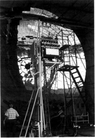
17 Chart 17 SOLASYS - Test Plant in Operation
 Comparison of hydrogen production cost by conventional and")
18 Chart 18 SOLASYS Economic Analysis (2006) Comparison of hydrogen production cost by conventional and solar reforming of natural gas (NG) depending on the NG price reported in 2004 by
 SOLASYS SOLREF Catalysis Reformer Operation")
19 Chart 19 SOLREF Solar Steam Reforming (SES6-CT ) SOLASYS SOLREF Catalysis Reformer Operation Pre-design of 1MW plant Conceptual layout of 50 MW plant Studies 1 MW th Prototype Plant e.g. in Southern Italy

20 Chart 20 Motivation & Consortium -Production costs of partly-solar hydrogen with less than 5 ct /kwh or 1.7 /kg H 2 (large scale, solar-only) are possible. -The solar driven process reaches profitability when the price of NG increases to about 40ct /Nm 3 -Eight participants from seven countries: -DLR, coordinator Germany -APTL/CERTH/CPERI, Greece -Weizmann Institute of Science, Israel -ETH Zurich, Switzerland -Johnson Matthey Fuel Cell Ltd, UK -HyGear B.V., The Netherlands -SHAP S.p.A., Italy -Region Basilicata, Italy
21 Chart 21 Project main objectives -Develop an advanced 400 kw th solar reformer -Investigate various catalyst systems -Simulate mass and heat transport and reaction in porous absorber -Perform thermodynamic and thermochemical analyses to support the system design phase -Operate the reformer with gas mixtures which represent the variety of possible feedstock on the solar tower at WIS, Israel, producing partlysolar hydrogen -Evaluate new operation strategies -Pre-design of a 1 MW th prototype plant in Southern Italy -Conceptual layout of a commercial 50 MW th reforming plant -Assess on potential markets including cost estimation and environmental, socio-economic, and institutional impacts
22 Chart 22 Solar Reformer - Improvements Insulation SOLREF Reformer: Secondary Extension - sun Quartz- Window Catalytic Ceramic Absorber Inlet Outlet Absorbed power: app. 400 kw th Feed-temperature: app. 450 C Outlet-temperature: app. 900 C absorber temp.: max C Operation pressure: optimal pressure 10 bars; max. 15 bars a Mass flow: 0.12 kg/s Vessel -outlet -inlet
23 Chart 23 Future Steps -Areas for market introduction -Addition of solar upgraded fuel into large scale CC power plants with mixing rate 5-10 % -Dual fuel operation - Solar reforming of biogas or landfill gas -Further research is directed to -Flexible feed gas composition -Modified process parameters including CO 2 separation and reforming -Next step towards market introduction -Pre-commercial solar reforming plant of 1-5 MW size adapted to the specific fuel and process conditions

24 Chart 24 Acknowledgement -Thanks to all our funding agencies especially the European Commission for funding the projects. -Thanks to all colleagues and partners who provided various contributions to this work.

25 Chart 25 Thank you very much for your attention!
26 Chart 26 LPG Storage & Supply Water Supply System SOLASYS Test Plant Evaporator LPG Purifier Steam Generator Ratio Control Electrical Preheater Coolers & Condensers Air Cooler Preheater Volumetric Reactor Receiver Air Prereformer Gas Turbine Concentrated Radiation G Combustor Water Syngas Storage Water Separator
 99.7 (96.3) 150.3 (139.4) CH 4 -conversion % 72.0 (73.3) 66.8 (65.3) 70.5 (65.0) Absorbed chemical kw 75.4 (74.7) 76.1 (72.7) 111.5 (100.6) Power Power-increase % 22.4 (22.2) 22.5 (21.5) 22.")
27 Chart 27 Results of reforming tests p receiver bar T reaction C Steam mass flow kg/h LPG mass flow kg/h Total absorbed power kw (99.9) 99.7 (96.3) (139.4) CH 4 -conversion % 72.0 (73.3) 66.8 (65.3) 70.5 (65.0) Absorbed chemical kw 75.4 (74.7) 76.1 (72.7) (100.6) Power Power-increase % 22.4 (22.2) 22.5 (21.5) 22.1 (20.0) Fuel saving % 18.3 (18.2) 18.4 (17.7) 18.1 (16.7) Values in ( ) are calculated

28 Chart 28 Indirect heated tube receiver: CSIRO Solargas -Indirect reactor technology -Second tower at the CSIRO Solar Centre Newcastle, NSW, Australia -Test facility for different Reactors -Tubular reactors up to 200 kw were tested -Other reactors were tested as well -600 kw decoupled -Rotary cylinder reactor from TITech, Japan -Campaign with a volumetric reactor is planned