HISTORY OF CONSTRUCTION 40 CFR (c)(1)(i) (xii) PLANT HAMMOND ASH POND (AP 2) GEEORGIA POWER COMPANY
|
|
|
- Bernice Griffith
- 5 years ago
- Views:
Transcription
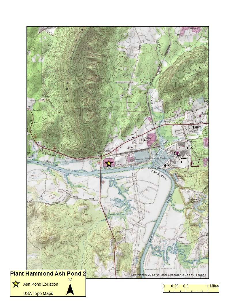
1 HISTORY OF CONSTRUCTION 40 CFR (c)(1)(i) (xii) PLANT HAMMOND ASH POND (AP 2) GEEORGIA POWER COMPANY (i) Site Name and Ownership Information: Site Name: Plant Hammond Site Location: Site Address: Rome, Georgia 5963 Alabama Highway SW Rome, GA Owner: Owner Address: Georgia Power Company 241 Ralph McGill Blvd Atlanta, GA CCR Impoundment Name: Plant Hammond AP 2 NID Identification Number: GA05204 EPA s Disposal of Coal Combustion Residuals from Electric Utilities Final Rule (40 C.F.R. Part 257 and Part 261), (c)(1), requires the owner or operator of an existing CCR surface impoundment to compile a history of construction. To the extent feasible, the following information is provided: (ii) Location: 34 15'04"N, 85 21'10"W See Location Map in the Appendix (iii) Purpose of CCR Unit: Plant Hammond is a four (4) coal fire unit electric generating facility. Plant Hammond has historically utilized four (4) ponds in the management of coal combustion residuals. AP 2 was designed to receive and store coal combustion residuals produced during the electric generating process at Plant Hammond. (iv) Watershed Description: Plant Hammond AP 2 is located within the Cabin Creek HUC 12 watershed which has a total area of 10,472 acres and the Morton Bend HUC 12 watershed which has a total area of 21,984 acres. AP 2 is located entirely within the Morton Bend watershed. The entire Plant Hammond property is located within the Upper Coosa HUC 8 watershed which has a drainage area of 1,025,639 acres. AP 2 does not receive stormwater run off from adjacent areas.
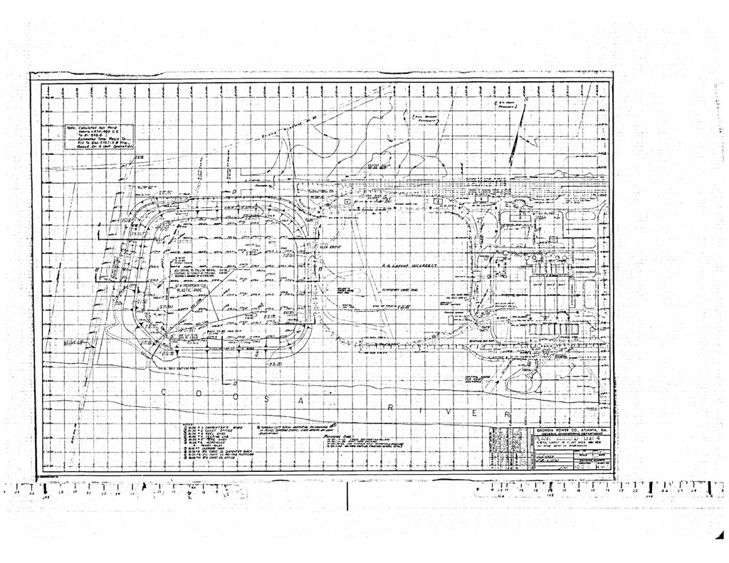
2 (v) Description of physical and engineering properties of CCR impoundment foundation/abutments: AP 2 is a diked structure with a 24 ft. high perimeter embankment. Borings drilled at AP 2 indicate clayey sand embankments and sandy clay foundation material. Borings drilled at other locations at the Plant Hammond site indicate that the clayey alluvium extends down to approximate elevation 565 ft to 570 ft, and is underlain by a 5 ft to 10 ft thick deposit of coarse sand and gravel above rock. (vi) Summary of Site Preparation and Construction Activities: AP 2 was commissioned in 1969 with a total storage capacity of 821,000 CY, a corresponding surface area of 21.2 acres, and a maximum embankment height of 24 feet. The embankment was constructed with borrow soils from within AP 2 and the excavation of the Unit #4 precipitator substructure area. The embankment was constructed with upstream and downstream slopes of 2H:1V. A diagonal separator dike was added to AP 2 in 1998, effectively dividing AP 2 in half. AP 2 is currently used as a dewatering facility for fly ash and bottom ash, with dewatering operations alternating between halves. The halves are hydraulically connected via 24 in corrugated metal pipes. Dewatered ash is excavated and transported to the nearby Huffaker Road facility, a permitted solid waste disposal location owned and operated by Georgia Power Company. (vii) Engineering Diagrams: The following drawings reflecting the construction of AP 2 can be found in the Appendix: Site Location Map Georgia Power Company Drawing H 400 General Layout of Plant Area and New Ash Pond West of Powerhouse Georgia Power Company Drawing H 401 Cross Sections and Volume Calculations for New Ash Pond West of Powerhouse Georgia Power Company Drawing C 406 Ash Pond Overflow Structure Georgia Power Company Drawing H 254 Ash Sluice Pope Trench Modifications Neatlines & Reinforcing Georgia Power Company Drawing E8543 Ash Pond #2 Separator Dike Location and Details Georgia Power Company Drawing E8544 Ash Pond #2 Excavation Plan for Northern Cell Georgia Power Company Drawing ES1844S1 Boring Locations and Cross Sections (viii) Description of Instrumentation: There are 2 piezometers installed along the crest of the southern embankment of AP 2 used to monitor water levels in the embankment.
3 (ix) Area capacity curves: Cumulative Volume in Acre Feet Plant Hammond AP 2 Area Capacity Curve Elevation of Pond in Feet (NAVD) Surface Area in Acres Volume Capacity Surface Area (x) Spillway/Diversion design features and capacity calculations: AP 2 does not have an open channel spillway. AP 2 was divided into a northern and a southern cell in 1998, each having an independent 24 in diameter CMP principal spillway which flows into a discharge basin in the northeast corner of the pond. The discharge from this basin is the 30 inch FRP recycle line to AP 1. The northern and southern cells also discharge via a 24 inch CMP into a smaller collection basin in the southwestern portion of AP 2. This basin serves as the emergency discharge for the northern and southern cells. The emergency flows are currently discharged to an unnamed creek to the Coosa River via a 24 in diameter high density polyethylene (HDPE) pipe. The upstream invert of this pipe is ft with a downstream invert of ft. The original auxiliary discharge structure has not been located and is assumed to be abandoned during the installation of the 24 inch HDPE pipe. The 24 inch HDPE outlet and inlet are visually inspected semi annually. As a significant hazard structure, AP 2 must be capable of safely storing and/or passing runoff resulting from the 24 hour, 1000 year storm event. The normal water surface elevation in AP 2 is feet. The top of dike elevation is feet. During the design storm, the peak water surface elevation is (leaving a freeboard of 0.3 feet below the top of dike).
4 (xi) Provisions for surveillance, maintenance and repair: Inspections of dikes are critical components and are conducted on a regular basis at least annually by professional dam safety engineers and at least weekly by trained plant personnel. In addition, inspections are performed after significant events such as storms. The inspections provide assurance that structures are sound and that action is taken, as needed, based on the findings. Safety inspections include numerous checklist items. Specific items vary from site to site but may include observations of such things as pond levels, weather conditions, rainfall since the prior inspection, instrument readings, conditions of slopes and drains, erosion, animal damage, ant hills, alignment of retaining structures and more. Dam safety engineers assess instrument readings, inspect any maintenance or remediation performed since the previous inspection, check the status of work recommended at prior inspections, ensure that emergency notification information is current and evaluate any items noted during plant personnel inspections. (xii) Known record of structural instability: There is no known record of structural instability for AP 2, and there are no major issues or repairs to Plant Hammond AP 2. Over the course of operation of AP 2, repairs of minor surface sloughs (veneer sloughs) on the downstream slope have been performed.
5 Appendix
6
7
8
9
10
11
12