Wet-To-Dry-Conversion. Bottom Ash Systems
|
|
|
- Basil Francis
- 5 years ago
- Views:
Transcription

1 Wet-To-Dry-Conversion Bottom Ash Systems


2 Wet-To-Dry Ash Handling Solutions The Evolution to Dry Ash Handling Due to recent high-profile ash pond failures, the Environmental Protection Agency (EPA) has released two rules that require utilities to re-evaluate wet ash handling practices. Effluent limitation guidelines (ELG) and Coal Combustion Residual (CCR) rules will tighten controls at coal-fired power plants on wastewater discharge and leaching of toxic metals and other pollutants to streams and groundwater. Utility companies still using retention ponds to store ash by-product have important choices as they look to replace wet systems with dry solutions. UCC understands the challenges utilities are facing and has assisted many coal-fired power plants to proactively convert their ash handling systems from wet to dry solutions. State-of-the-art ash handling systems from UCC offer greater reliability and the broadest range of customized solutions for regulatory compliance. INDUSTRY TRENDS INCREASING GOVERNMENT REGULATIONS ASH POND CAPACITY CONSTRAINTS WATER AVAILABILITY GROWING DEMAND FOR REUSE OF ASH What is Dry? Dry is often used in the industry to represent placement into a landfill, not necessarily the method of conveying. The objective for most utilities is to eliminate the pond not always the use of water from the ash conveying process for fly and bottom ash. Some plants, however, will need to minimize or eliminate water from the conveying process due to limited water supply or environmental concerns. These conditions frame the available choices, which range from continued use of water to 100% elimination of water.


 Pressure Systems (NUVA FEEDER, DEPAC and MultiDAC TM")
3 Experience Matters United Conveyor Corporation is dedicated to the development of technology, systems and products that address the needs of coal-fired power plants. As a recognized industry leader, we partner with utilities, design engineering firms and power generation companies worldwide to help deliver solutions that make a positive impact on plant performance. Since 1920, UCC has set the standard for innovation, performance and customer service. We have the broadest offering of bottom ash and fly ash systems to deliver optimal performance while addressing all environmental regulations. UCC ASH HANDLING SOLUTIONS ARE... SPECIFICALLY ENGINEERED FOR EACH PLANT DESIGNED TO IMPROVE PLANT PERFORMANCE ENVIRONMENTALLY FRIENDLY SOLUTIONS One Company...the Right Solution Fly Ash Systems Vacuum Systems (NUVEYOR ) Pressure Systems (NUVA FEEDER, DEPAC and MultiDAC TM ) Combination Vacuum/Pressure Systems High Density Slurry System Bottom Ash Systems Continuous Dewatering and Recirculation Systems (CDR TM ) Submerged Flight Conveyors (SFC TM ) Pneumatic Ash Extractors (PAX TM ) Vibrating Ash Extractors (VAX TM ) Traditional Recirculation Systems

4 Ash Bottom Ash Choices Choosing The Right Dry Bottom Ash System United Conveyor offers the broadest range of state-of-the-art dry bottom ash handling solutions. Four different system types Hydraulic, Mechanical, Pneumatic and Vibratory have been developed to address the particular characteristics of each individual power plant. With hundreds of installations and nearly a century of experience, UCC provides the confidence and peace of mind our customers demand. Each plant must evaluate the importance of different criteria when selecting the right bottom ash system. Common Criteria Used to Evaluate Fly Ash Choices: Physical Space Constraints What system choices are available? Design, Material and Installation Costs What is the budget? Maintenance Costs What is the 20-year life-cycle cost? Time Available for Installation How long is the outage? Water Usage/Availability How much water is available for ash conveying and disposal? Operating Costs What are the power consumption requirements? Multiple Unit Synergies Can storage tanks and silos be used for multiple units? Storage/Disposal How will the bottom ash be stored/used? Bottom Ash Systems Traditional Recirc. (Hydraulic) CDR (Remote SFC) SFC (Mechanical) PAX (Pneumatic) VAX (Vibratory) Total Lead Cost $$$$ $ - $$ $ $$ $$$ Lead Time 12 Months 12 Months 9 Months 12 Months 12 Months Outage Requirement Water Consumption Power Consumption Boiler and Yard Space Operations and Maintenance Costs Pre-Outage Construction 6 Months 6 Months 2 Months 3 Months 3 Months Outage Construction 5 Days 5 Days 3-4 Weeks 8 Weeks 6 Weeks Outage Start-Up 0-3 Days 0-3 Days 1-2 Days 3-4 Days 1-2 Days Make-Up Water 600 gpm 600 gpm 50 gpm None None Cooling Water 200 gpm 200 gpm 400 gpm None None Conveying Water (recirculating) Pumps gpm gpm None None None HP HP Primary HP Recirc. 50 HP None None Blower/Fans None None None 200 HP 50 HP Mechanical Drives 50 HP 50 HP 100 HP 50 HP 75 HP Yard Piping Corridor Yes Yes No Yes No Boiler House Exit Corridor No No Yes No Yes Yard Footprint 9000 sq. ft sq. ft sq. ft sq. st sq. ft. Pumps Yes Yes No No No Blowers/Fans No No No Yes Yes Refractory Yes - existing Yes - existing Usually None Yes Usually None Conveyor Chain Replacement No Yes Yes No No Crushers Yes - existing Yes - existing Usually None Yes (2-3) Yes Conveying Piping/Valves Yes Yes No Yes No Table information based on typical installation.


5 Systems BOTTOM ASH SYSTEMS CLOSED-LOOP RECIRCULATION SYSTEMS (CDR TM ) SUBMERGED FLIGHT CONVEYOR (SFC TM ) PNEUMATIC ASH EXTRACTOR (PAX TM ) VIBRATORY ASH EXTRACTOR (VAX TM ) TRADITIONAL RECIRCULATION SYSTEM Certain plant limitations will reduce available conversion options. For example, if the ash pond needs to be eliminated in the next months and there is no chance of a severalweek outage to replace equipment, the only choice becomes a traditional Hydraulic Recirculation or Continuous Dewatering and Recirculation System. If complete elimination of water is required, then two 100% dry options are available: PAX Pneumatic Ash Extractor preferred retrofit system to overcome structural barriers with excellent routing flexibility VAX Vibratory Ash Extractor retrofit system with design flexibility to address structural layout or headroom requirements with no moving parts under the boiler NUMBER OF INSTALLATIONS RECIRCULATION SYSTEM SUBMERGED FLIGHT CONVEYOR PNEUMATIC ASH EXTRACTOR HEAVY-DUTY HOT INDUSTRIAL APPLICATIONS UTILIZING VIBRATORY TECHNOLOGY ,000+
.")

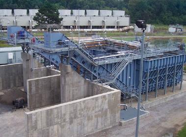
6 Bottom Ash Continuous Dewatering & Recirculation ( Latest Innovation for Zero Liquid Discharge The CDR System represents a major technical advancement in bottom ash conveying by combining the benefits of a traditional recirculation system with the proven dewatering technology of a Submerged Flight Conveyor (SFC). The CDR System is ideal for plants that currently have sluice conveying for bottom ash, economizer ash and mill rejects/pyrites, and are looking to avoid the costly and extended outage time typically associated with other system installations. In addition to a simple and fast conversion, the CDR System greatly minimizes numerous operational and maintenance concerns prevalent in traditional dewatering technologies. ELIMINATES ASH STORAGE PONDS NO OUTAGE TIME REQUIRED NO CHANGE TO EXISTING HOPPERS GREATLY REDUCES PLANT WASTEWATER System Operation The CDR System ties into the existing sluice conveying lines, diverting slurry discharge to a remote conveyor located outside of the boiler house. The conveyor, or remote SFC, is highly engineered to combine the necessary functions of ash dewatering, particulate settling and surge capacity into a single unit, making it a very cost-effective solution. During operation, material is conveyed through a slurry pipe and discharged into the forward section of the remote SFC. Upon entry, the velocity of the slurry is rapidly reduced allowing the ash to directly settle into the conveying section. Material collected in the conveying section is then carried by flights up the dewatering ramp, where it is discharged into a load-out bunker or secondary conveying arrangement. The sluice conveying water is then pumped back to the boiler house to complete the closed-loop, zero liquid discharge system. NUMBER OF INSTALLATIONS RECIRCULATION SYSTEM SUBMERGED FLIGHT CONVEYOR


7 Systems TM CDR ) The CDR System is designed to accept slurry discharge from one or more operating units. System installation requires no modification to existing ash handling equipment beneath the boiler and can be commissioned with the plant online, resulting in no outage time. This wet-to-dry conversion option is most favorable when considering capital cost and maintaining plant availability. [REMOTE SFC]


8 Bottom Ash Traditional Recirculation System Simple Conversion with a Successful Track Record A traditional closed-loop recirculation system converts a wet sluice system into a dry ash system without change to the existing bottom ash hoppers. This system reuses the conveying water and only requires a small amount of make-up water. A traditional recirculation system replaces the ash pond with dewatering bins, a clarifying (settling) tank and surge (storage) tank. This is the system of choice when water supplies are available and minimal outage time is required to make the conversion. Once the system components have been installed, the Traditional Recirculation System requires only a few days of outage time to reroute the pipes. SHORTEST OUTAGE TIME FOR CONVERSION CONTINUED USE OF EXISTING BOTTOM ASH HOPPERS EASILY INCORPORATES MILL REJECTS ELIMINATES ASH STORAGE PONDS System Operation In a typical system, two dewatering bins are required; one bin fills while the other is dewatered and unloaded into trucks or rail cars. Water overflows to the settling tank and then onto the surge tank. In the settling tank, a large percentage of the fine ash carryover settles to the bottom and is returned to the dewatering bin. Water leaving the settling tank is directed to the surge tank where recirculation pumps return the water to the existing bottom ash sluice system.

 The conveyor is manufactured in various standard widths, making it easily adaptable to many boiler sizes.")
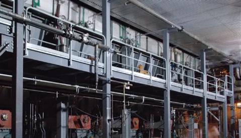
9 Systems TM Submerged Flight Conveyor (SFC The Industry Leader with Proven Performance The Submerged Flight Conveyor (SFC) is a proven bottom ash system and the most cost-effective choice when compatible with the plant equipment layout. When reducing water consumption is a major deciding factor, the typical SFC system provides the lowest cost option. With installations operating around the world, this system has demonstrated proven performance and reliability. ) The conveyor is manufactured in various standard widths, making it easily adaptable to many boiler sizes. The SFC system is compatible with pulverized coal-fired (PC) boilers, wet bottom (slagging) boilers, stoker-fed or traveling grate boilers and incinerators. CONTINUOUS REMOVAL OF ASH LOW POWER CONSUMPTION EASILY INCORPORATES MILL REJECTS ELIMINATES ASH STORAGE PONDS System Operation Operation of the Submerged Flight Conveyor is very simple. Ash falls from the boiler into a water-filled, upper trough that quenches and cools the ash. Chains and flights move the ash along the horizontal trough and up a dewatering ramp. At the top of the ramp, the ash falls through a discharge chute into a concrete bunker, where it can be loaded into trucks for final disposal. The flights continue through the lower (dry) chamber to the rear of the conveyor and then return to the upper trough.

 Three subsystems comprise a typical PAX System: A dry hopper where the ash is collected, crushed and fed to the vacuum system. A vacuum system for dry ash removal and conveying.")
10 Bottom Ash Pneumatic Ash Extractor (PAX Time Proven Technology with Routing Flexibility The Pneumatic Ash Extractor (PAX) System is the preferred retrofit system to overcome structural barriers when complete elimination of water is required. The PAX system utilizes time-proven dry ash storage and vacuum conveying to collect and transfer bottom ash in a dry state. This system also provides heat recovery and improved boiler efficiency. TM ) Three subsystems comprise a typical PAX System: A dry hopper where the ash is collected, crushed and fed to the vacuum system. A vacuum system for dry ash removal and conveying. A storage bin and unloading equipment for final disposal. EASILY RETROFITTED AROUND STRUCTURAL BARRIERS GREATER HEAT RECOVERY DOES NOT REQUIRE WATER ELIMINATES ASH PONDS [100% DRY] System Operation Steep walls and bottom discharge promote gravity flow of ash down the hopper. Hydraulically operated grid doors located at the bottom of the hopper allow ash and clinkers to pass into a crusher. When the doors are closed, air flows into the hopper cooling the ash and burning residual carbon. From the crusher, smaller ash particles flow into a vacuum conveying system where they will be conveyed to an ash silo, storage bin or transfer truck.

![) [100% DRY] The VAX system features a rugged design and durable construction to handle the extreme operating conditions of coal-fired power plants.](/docs-images/86/93530681/images/11-1.jpg "Unlike other mechanical bottom ash conveyor systems, there are no moving belts or hinged joints that can become damaged from large slag falls or foreign material such as soot blower or tube shields.")
11 Systems TM Vibratory Ash Extractor (VAX Next Generation Technology for Dry Bottom Ash Handling The Vibratory Ash Extractor (VAX) System is the latest evolution of dry bottom ash technology, transporting and cooling ash in one efficient process. It is the most reliable, heavy-duty and cost-effective dry bottom ash handling system on the market. ) [100% DRY] The VAX system features a rugged design and durable construction to handle the extreme operating conditions of coal-fired power plants. Unlike other mechanical bottom ash conveyor systems, there are no moving belts or hinged joints that can become damaged from large slag falls or foreign material such as soot blower or tube shields. The result is system reliability and reduced risk of unplanned outage. PROVEN TECHNOLOGY HIGHEST HEAT RECOVERY LOWER OPERATING COST ELIMINATES ASH STORAGE PONDS System Operation Designed for simplicity and safety with no internal moving parts, the VAX System requires virtually no maintenance and its overall operation is unmatched in the industry. Using proven vibratory conveying technology, ash is advanced through a series of successive throws using an oscillatory toss-and-catch motion. Controlled forced draft air enters through the vibratory conveyor deck and surrounds the entire ash surface as it is suspended between throws, creating a fluidized bed of ash. The result is increased cooling and combustion.
12 The UCC Commitment As an industry innovator, we have long been at the forefront of ash handling technology. We recognize the importance of providing customers with the best equipment and latest technology that meet their demanding requirements and plant needs. With our own advanced testing and technology lab, we are able to maintain control over the quality and delivery of our systems and equipment. The result is superior and predictable performance for our customers. Our dedicated team of engineers, sales, service and in-house designers spans the globe covering six continents, assuring you that we can provide exceptional service whenever needed. This is our commitment to you. UCC Material Handling Solutions Fly Ash (Dilute, Medium and Dense Phase) Vacuum Systems Pressure Systems Bottom Ash (Wet and Dry) Hydraulic Systems Pneumatic Systems Mechanical Systems Vibratory Systems Mill Rejects Hydraulic System Pneumatic Systems Economizer Ash Hydraulic Systems Mechanical Systems Pneumatic Systems Dry Sorbent Injection Predictive (CFD) Modeling On-Site Testing and Demonstration Pneumatic Systems Installation Lime Handling Truck and Rail Unloading Pneumatic Systems Global Operations in: United States Europe Thailand China India Systems in over 60 Countries System Components Crushers Mixer/Unloaders Gates /Valves Pipe/Fittings Filter/Separators Tanks/Vessels unitedconveyor.com UCC is a registered trademark of United Conveyor Corporation. All enclosed content is provided for information only. United Conveyor Corporation reserves right to change without notice any information contained within. M United Conveyor Corporation