|
|
|
- Sheryl Ferguson
- 5 years ago
- Views:
Transcription

1
2

3
4
 Ignition of the gas is on top of the burner. (C) Incomplete combustion yields yellow lazy flame.")
5 Gas Combustion Figure (A) Primary air is induced into the air shutter by the velocity of the gas stream from the orifice. (B) Ignition of the gas is on top of the burner. (C) Incomplete combustion yields yellow lazy flame. Any orange color indicates dust particles drawn in with the primary air
6
7 Standard Air 20.9% oxygen 78% nitrogen 1% other gasses

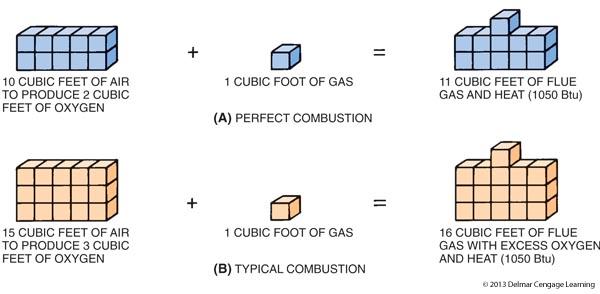
8 Complete Combustion CH4 + 3O2 = Heat + 2H2O + CO2 + O2 Where CH4 = 1 cubic foot of methane gas (natural gas) 3O2 = 3 cubic feet of Oxygen Heat 1027 BTU s of energy produced from the chemical reaction 2H2O = 2 cubic feet of water Vapor CO2 = 1 cubic feet of carbon dioxide O2 = 1 cubic foot of excess oxygen
 Where CO = Carbon")
9 Incomplete Combustion CH4 + 3O2 = Heat + 2H2O + CO (+/- O2) Where CO = Carbon Monoxide
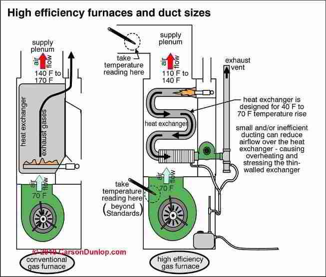
10 High-Efficiency Gas Furnaces (cont'd.) Annual fuel utilization efficiency rating (AFUE) allows consumer to compare furnace performance before buying Furnace efficiency ratings are determined by amount of heat transferred to the heated medium Conventional furnace: 78-80% AFUE Mid-efficiency furnace: 78-83% AFUE High-efficiency furnace: 87-97% AFUE
11 Gas Combustion Requires fuel, oxygen, and heat Ignition temperature for natural gas is ºF Perfect combustion produces carbon dioxide, water vapor, and heat Poor combustion produces carbon monoxide, soot, and other products Flame should be blue with orange tips Yellow tips indicate carbon monoxide
12 Courtesy of Bill Spohn, Testo Combustion Diagram The ideal operating range is a setting with excess air. Flue gas components Incomplete CO Stoichiometric line Ideal operating range of burners Complete Eff. CO 2 O 2 Excess Fuel Excess Air
13 What is flue gas? Carbon dioxide CO 2 Carbon monoxide CO Sulfur dioxide SO 2 O 2 - balance How is it formed? Nitrogen oxide NO x Water vapor H 2 O Smoke (oil systems) air Oxygen (20.9%) water vapor Nitrogen (79%) Courtesy of Bill Spohn, Testo fuel-residual ashes fuel carbon hydrogen sulfur oxygen nitrogen water
14 What is Carbon Monoxide? CO originates from incompletely (oxidized) burnt carbon (fuel). It is very dangerous for human and animals, because it prevents the absorbstion of oxygen in the blood stream. Reasons for the formation: - fuel rich mixture - Improper venting - too early cooling of the flame (1128 F) CO is expressed in parts per million (ppm). Courtesy of Bill Spohn, Testo
15 CO Sources Fuel burning furnaces and hot water heaters Fuel burning boilers Fuel burning space heaters Kitchen ranges & ovens Auto emissions Attached garages Fireplaces Tobacco smoke Courtesy of Bill Spohn, Testo
16 Characteristics of CO Odorless Colorless Tasteless Mixes well in air Does not stratify Follows air flow in a structure Poisonous Courtesy of Bill Spohn, Testo
17 CO Health Effects 35 ppm NIOSH Permissible Exposure Limit 8 hours 200 ppm NIOSH Ceiling 15 minutes 200 ppm Slight headache with 2-3 hours 400 ppm Headache within 1-2 hours 800 ppm Sickness & twitching of limbs within 1-2 hours; unconsciousness in 2 hours 1,600 ppm Headache within 20 minutes; death within 2 hours 3,200 ppm Death in 30 minutes 6,400 ppm Death in minutes 12,800 ppm Death in 1-3 minutes Courtesy of Bill Spohn, Testo

18 CO Testing Fuel Burning Appliances Sample from entry of home to exit of home Sample around all un-vented appliances Sample before draft diverter of atmospheric devices Sample where you may suspect CO Courtesy of Bill Spohn, Testo Graphics COAD 1996
19 Types of Furnaces Atmospheric Natural Draft Buoyancy Creates NEGATIVE Pressure in Flue Induced Draft Fan Creates NEGATIVE Pressure in Flue Power Draft Power Vent Fan Creates POSITIVE Pressure in Flue Condensing Sealed combustion
 fuel Natural Gas Light Oil Heavy Oil Propane Wood Courtesy of Bill Spohn, Testo")
20 Calculating Combustion Efficiency Oxygen O 2 The analyzer uses the oxygen and net temperature measurements in fuel specific equations to give the efficiency, CO2 and excess air readings. StackTemp Air Temp Ambient Temp (combustion air) fuel Natural Gas Light Oil Heavy Oil Propane Wood Courtesy of Bill Spohn, Testo

21 Combustible Gas Leak Detection

22 Spillage, Flame Roll-Out, Backdrafting

23 Testing for CO in the Appliance Test undiluted CO

24 Testing Draft Notice the hole in the boiler flue pipe
 in Inches of Water Column, IWC")
25 Testing Draft Some combustion analyzers test for pressure as well as CO. This one records pressure (draft) in Inches of Water Column, IWC
 Or sample in stack termination (CO) Follow Manufacturer s Specs Graphics COAD 1996")
26 Testing Condensing Furnaces Test under Steady State Operating Conditions Sample around burner (CO) Sample efficiency in plastic vent pipe (MFG or authority) Or sample in stack termination (CO) Follow Manufacturer s Specs Graphics COAD 1996
27 Gas Combustion (cont d.) Only gas pressure and primary air can be adjusted in the field Gas/air mixture is important 0-4% natural gas will not burn; 4-15% natural gas will burn but can explode; % natural gas will not burn or explode Limits of flammability vary for gases Extra primary air supplies better combustion
28 What Information is Important? Combustion Efficiency 02, Temperature, Fuel Reduce Fuel Cost - Savings Carbon Dioxide (CO 2 ) O 2 Reference (3%, air free) Emission Conversions Excess Air To determine Operating Condition Diluting effects of excess air (NO, NO2, SO2, CO) Weight of pollutant (lbs/mbtu) Extra Air for Combustion Courtesy of Bill Spohn, Testo

 Always")
29 Typical Readings Gas Fired Power Burners Oxygen : 3 % - 6 % Carbon Dioxide: 8.5 % - 11 % Stack Temp : 275 ºF to 570 ºF Draft: -.02WC to -.04WC in the Stack Carbon Monoxide: <100 ppm (diluted) Always Follow Mfr s Specifications Courtesy of Bill Spohn, Testo
30 Natural gas Gas Fuels 90-95% methane and other hydrocarbons Lighter than air (specific gravity = 0.60) Colorless, odorless, and not poisonous Displaces oxygen and can lead to suffocation Odorants are added for detection purposes Produces about 1050 Btu per cubic foot when burned with air

31 Gas Fuels Figure A digital manometer being used to measure gas pressure in inches of water column Courtesy Ferris State University. Photo by John Tomczyk