GEOTECHNICAL INVESTIGATION REPORT STAGE 1 RAS PUMP STATION UPGRADE SAN JOSE CREEK WATER RECLAMATION PLANT
|
|
|
- Violet Robinson
- 5 years ago
- Views:
Transcription
1 GEOTECHNICAL INVESTIGATION REPORT STAGE RAS PUMP STATION UPGRADE SAN JOSE CREEK WATER RECLAMATION PLANT County Sanitation Districts of Los Angeles County Whittier, California Prepared for: County Sanitation Districts of Los Angeles County 955 Workman Mill Road Whittier, California 9060 Prepared by: AMEC 2 Innovation Drive, Suite 200 Irvine, California 9267 (949) October 29, 203 Revised December 2, 203 Project No


2
3 TABLE OF CONTENTS Page.0 INTRODUCTION.... PROPOSED CONSTRUCTION....2 SCOPE OF WORK DATA REVIEW FIELD INVESTIGATION AND LABORATORY TESTING PRE-DRILLING ACTIVITIES EXPLORATORY BORINGS LABORATORY TESTING DISCUSSION OF FINDINGS SURFACE CONDITIONS SUBSURFACE CONDITIONS ENGINEERING PROPERTIES GROUNDWATER CONDITIONS LIQUEFACTION GROUND MOTION PARAMETERS RECOMMENDATIONS FOR DESIGN AND CONSTRUCTION EARTHWORK Site Preparation and Grading Subgrade Preparation Fill Materials and Compaction Criteria Open-Graded Crushed Rock Sand-Cement Slurry Select Sand General Fill/Backfill Site Drainage DESIGN GROUNDWATER LEVEL POTENTIAL SHALLOW FOUNDATIONS BORING B- LOCATION Bearing Capacity and Settlement Lateral Load Resistance PUMP STATION STRUCTURE Recommendations for Potential Foundation Design Approaches Thickened Floor Slab Extended Floor Slab Tension Piles Below Grade Walls BURIED YARD PIPELINE Nomenclature Bearing Capacity and Settlement Bedding Material Pipe Zone Backfill Trench Zone Backfill Backfill Placement and Compaction Requirements Modulus of Soil Reaction P:\ \ \Docs\Geotechnical Investigation Report Final\Revised\Revised 223\FINAL_Text_223.docx AMEC i
4 TABLE OF CONTENTS (Continued) 7.7 PAVEMENT CORROSION AND CHEMICAL ATTACK RESISTANCE CONSTRUCTION CONSIDERATIONS EXCAVATION DIFFICULTY DEWATERING CONSTRUCTION SLOPES TEMPORARY SHORING Excavation, Design, Planning, and Maintenance Ground Support Systems Soldier Pile and Wood Lagging Systems Slide Rail Systems Continuous Sheet Piling Removal of Support Systems Excavation and Underpinning Plans Temporary Lateral Earth Pressures Soldier Piles and Lagging Sheet Piles TUNNELING Potential Ground Settlement Hazardous Gases POST INVESTIGATION SERVICES CLOSURE REFERENCES TABLES Table Table 2 Table 3 Table 4 Table 5 Piezometer B- Groundwater Levels Summary of Historic Groundwater Level Data Crushed Rock Gradation Select Sand Gradation Flexible Asphalt Concrete Pavement Recommendations FIGURES Figure Figure 2 Figure 3 Figure 4 Figure 5 Figure 6 Figure 7 Figure 8 Site Vicinity Map Boring Location Plan Temporary Piezometer Construction Detail Geologic Cross Section A-A Groundwater Monitoring Well Location Plan Historical Groundwater Levels Uplift Capacities of Driven SPPC Piles for Pump Station Lateral Earth Pressure for Permanent Walls below Grade (Open Excavation Condition) P:\ \ \Docs\Geotechnical Investigation Report Final\Revised\Revised 223\FINAL_Text_223.docx AMEC ii
5 TABLE OF CONTENTS (Continued) Figure 9 Figure 0 Lateral Earth Pressure for Permanent Walls below Grade (Adjacent to Temporary Shoring System) Lateral Earth Pressure for Temporary Shoring System APPENDICES Appendix A Appendix B Appendix C Previous Investigations Field Exploration Laboratory Test Results Field Exploration Program Laboratory Testing Program P:\ \ \Docs\Geotechnical Investigation Report Final\Revised\Revised 223\FINAL_Text_223.docx AMEC iii
6 GEOTECHNICAL INVESTIGATION REPORT Stage RAS Pump Station Upgrade San Jose Creek Water Reclamation Plant Whittier, California.0 INTRODUCTION AMEC Environment & Infrastructure, Inc. (AMEC) prepared this geotechnical investigation report for the proposed Stage RAS Pump Station Upgrade at County Sanitation Districts of Los Angeles County s (Sanitation Districts) San Jose Creek Water Reclamation Plant (WRP) in Whittier, California. The vicinity of the WRP is shown on Figure. AMEC performed this geotechnical investigation in accordance with the task agreement between the Sanitation Districts and AMEC (Task Agreement Form [TAF] No. 64) as part of on-call geotechnical engineering services.. PROPOSED CONSTRUCTION Based on our review of the design plans dated August 203 provided by the Sanitation Districts, the proposed upgrade will include construction of a new pump station 29.5 feet to 3.5 feet deep with a wet well, four 30-inch diameter pipelines, and several buried electrical duct banks. The pump station will be approximately 9-foot by 3-foot in plan view. Location of the pump station is shown on Figure 2. At the time AMEC conducted the geotechnical investigation and prepared a draft of this report, the project included a proposed electrical control building at the current location of the pump station. Following our draft report, the Sanitation Districts changed the initial layout of the proposed structures. After submittal of our draft report, the proposed locations of the control building and pump station were switched, with control building being at the current location of the pump station shown on Figure 2 and vice versa. Later, the electrical control building was removed from the project. The former locations of these two facilities were shown on Sheet No.: Fig 4-7A Alternative No. 2A Overall Plan dated March 200 provided previously by the Sanitation Districts. It is our understanding that the pump station will be supported by a structural mat foundation. The proposed buried yard pipeline, proposed jacking pits, and other three proposed pipelines - two below ground beneath the chlorine contact tanks and one above ground located in the area of the pump station - are also shown on Figure 2. According to the design plans, the two proposed pipelines beneath the chlorine contact tanks will be 30-inch diameter and run parallel to each other at a spacing of 6 feet center to center. The design plans indicate the pipelines will be installed using tunneling techniques (likely jack and bore method) and housed in 48- inch diameter jacking steel casing. The top of the jacking casing will be approximately 5.5 feet below the bottom of the chlorine contact tanks. The proposed yard pipeline will be typically 20 AMEC P:\ \ \Docs\Geotechnical Investigation Report Final\Revised\Revised 223\FINAL_Text_223.docx
7 to 32 feet from the outside walls of the chlorine tanks and final sedimentation tanks, and will be installed using cut-and-cover techniques. It is anticipated yard pipeline will be buried about 3 to 9 feet below ground surface based on the August 203 design plans. Based on the design plans, two buried duct banks (B and B2) will also be installed using tunneling techniques. These duct banks and their proposed jacking pits are shown on Figure 2. Duct bank B will be housed in two 24-inch diameter 45-foot long steel casings at a spacing of 4 feet center-to-center. Duct bank B2 will be housed in one 30-inch diameter 22- foot long steel casing. The top of the jacking casings for these duct banks will be approximately feet to 5 feet below ground surface. These duct banks will cross beneath several existing underground pipelines and some roadways. The remaining duct banks will be shallowly buried using cut-and-cover techniques. Our geotechnical investigation did not include assessing the soil conditions along the shallowly buried duct banks, therefore, design recommendations for these duct banks are not provided in this report..2 SCOPE OF WORK Our scope of work consisted of the following: Preparing a Health and Safety Plan. Reviewing previous geotechnical reports prepared for previous upgrades at the WRP facility. Calling Underground Service Alert (USA) before drilling activities to mark buried utilities in the area of the borings. Performing a geophysical survey to help clear boring locations. Drilling two hollow-stem auger (HSA) borings, one to 26 feet depth below ground surface (bgs) and the other to 66 feet bgs. Collecting soil samples for geotechnical laboratory testing. Installing a temporary open-standpipe-type PVC piezometer in the 66-foot-deep borehole. Performing engineering analyses for the proposed upgrades. Preparing a letter report that summarizes our results and provides recommendations for design and construction of proposed construction. 2.0 DATA REVIEW Before initiating the field exploration and laboratory testing programs, AMEC reviewed three geotechnical reports, previously prepared by LeRoy Crandall and Associates (LCA, 968), GeoLogic Associates (GeoLogic, 200), and Van Beveren and Butelo, Inc (VBB, 2002), and a AMEC P:\ \ \Docs\Geotechnical Investigation Report Final\Revised\Revised 223\FINAL_Text_223.docx 2
8 previous design drawing of the upgrades (Sheet No.: Fig 4-7A Alternative No. 2A Overall Plan dated March 200). LCA (968) presents the results of a geotechnical investigation for the site of the WRP before construction of the WRP. LCA (968) drilled a total of 22 borings using 8-inch-diameter bucket type drilling equipment to depths ranging between 5 and 30 feet from the predevelopment ground surface elevation ranging between 246 feet above mean sea level at the southwest side to 255 feet at the northeast side of the property. LCA encountered young alluvial deposits primarily consisting of sand with occasional silty sand and silts. Based on LCA (968) boring logs, sand typically included 0 to 20 percent gravel. LCA (968) encountered free groundwater in borings at depths ranging from 23 to 27 feet bgs during drilling in July of 968. The locations of borings drilled as part of LCA (968) in the vicinity of the proposed Stage RAS Pump Station Upgrade are shown on Figure 2. Logs of these borings and laboratory testing relevant to this project are included in Appendix A. GeoLogic (200) conducted a seismic assessment evaluation for both the San Jose Creek and Los Coyotes Water Treatment Plants. Adjacent to the existing chemical and chlorination buildings at the WRP, GeoLogic (200) drilled two HSA borings to a depth of 52.5 feet bgs, and conducted one cone penetration test (CPT) probe to a depth of 25 feet bgs. GeoLogic (200) encountered medium dense to very dense silty sand, sandy silt, gravel, and stiff clay in these borings and CPT probe. A clay layer was encountered at depths greater than 40 feet. The CPT was completed to 25 feet bgs, where the probe encountered refusal in sand and gravel. Groundwater was encountered at a depth of 44 feet bgs in boring SJC-B-2 during drilling, which was at approximate Elevation 22 feet. Free groundwater was not reportedly encountered in boring SJC-B- during drilling, although wet soil conditions were encountered at a depth of 42 feet bgs (approximate Elevation 24 feet). The drilling was performed on September 25, The locations of borings drilled as part of GeoLogic (200) in the vicinity of the proposed upgrades are shown on Figure 2. Logs of these borings and laboratory testing relevant to this project are included in Appendix A. VBB (2002) provides foundation design recommendations for two ammonia tank pads; one of which is located approximately 300 feet north of the proposed RAS Pump Station. VBB (2002) drilled one HSA boring to a depth of 50 feet bgs and conducted one CPT probe to a depth of 36.5 feet bgs at this tank pad location. VBB encountered fill soils consisting of silty sand from ground surface to 5 feet bgs. VBB (2002) indicated the fill soils were not uniformly well compacted and considered them unsuitable for foundation support. Underlying the fill soils, VBB encountered alluvium consisting of silty sand with gravel. Similar to the borings by GeoLogic (200), VBB also encountered stiff clayey silt at a depth of 43 feet bgs. VBB did not encounter free groundwater during drilling, although the clayey silt below 43 feet bgs appeared to be saturated based on the moisture and dry density of a sample collected in the clayey silt. AMEC P:\ \ \Docs\Geotechnical Investigation Report Final\Revised\Revised 223\FINAL_Text_223.docx 3
9 The drilling was performed on May 7, The locations of borings drilled as part of VBB (2002) in the vicinity of the proposed upgrade are shown on Figure 2. Logs of these borings and laboratory testing relevant to this project are included in Appendix A. 3.0 FIELD INVESTIGATION AND LABORATORY TESTING The field investigation and laboratory testing program included pre-drilling activities, drilling two exploratory borings and collecting soil samples, converting one of the boreholes to a temporary open-standpipe-type piezometer, and laboratory testing of soil samples retrieved during exploratory drilling. The scope of the field exploration program was conducted in general accordance with the scope in the TAF No. 64. Field activities were conducted between August 2 and 3, 202, under the supervision of an AMEC engineer. Key aspects of the field program are described below. The results of the field exploration program, including logs of the borings are provided in Appendix B of this report. The laboratory testing program including the test results are provided in Appendix C. 3. PRE-DRILLING ACTIVITIES AMEC obtained a well permit for boring B-, which was converted to a temporary piezometer, from the County of Los Angeles Department of Environmental Health prior to drilling. Subsurface Surveys and Associates, Inc. of Carlsbad, California, was retained to provide private utility locating services. Underground Service Alert was notified at least two working days before drilling to locate buried utilities in the vicinity of the proposed borings. The boring locations were also approved by a representative of the Sanitation Districts. 3.2 EXPLORATORY BORINGS The field exploration program conducted by AMEC included drilling two HSA borings, B- and B-2, at the approximate locations shown on Figure 2, and collecting soil samples. Boring B- and B-2 were drilled to depths of approximately 66 feet bgs and 26 feet bgs respectively. As discussed in Section., at the time AMEC conducted the field exploration, an electrical control building was proposed and the locations of the control building and pump station were switched. As a result, AMEC drilled the deeper boring B- at the former location of the pump station and the relatively shallower boring B-2 at the former location of the control building. As a consequence, the bottom of boring B-2 is about 5 feet shallower than the proposed installation depth of the pump station. Soil samples were collected from each boring at selected depth intervals using a Standard Penetration Test (SPT) sampler and California-Modified sampler. The hammer blow counts required to drive the SPT and California-Modified split spoon samplers to the desired depths were recorded. Bulk samples were also obtained at selected depths. Detailed descriptions of field exploration and sampling procedures are provided in Appendix B. AMEC P:\ \ \Docs\Geotechnical Investigation Report Final\Revised\Revised 223\FINAL_Text_223.docx 4
10 Upon completion of drilling, boring B- was converted to an open-standpipe-type piezometer. The piezometer is screened between 25 feet and 65 feet bgs. The construction details of the temporary piezometer are shown on Figure 3. Earth materials were visually classified in the field in general accordance with the Unified Soil Classification System and ASTM International Test Procedure (ASTM) D 2488 by observation of the samples and cutting returns. Soil samples were transported to AMEC s laboratory for testing to help characterize subsurface conditions and evaluate engineering properties of encountered materials. 3.3 LABORATORY TESTING AMEC performed laboratory tests on soil samples to evaluate engineering properties of the site soils. Tests were performed in general conformance with relevant ASTM procedures. Tests performed included moisture content and dry density, percent passing No. 200 sieve, Atterberg limits, expansion index, direct shear, consolidation, and compaction. Corrosion testing was performed in accordance with California Department of Transportation (Caltrans) methods. Test results are presented in Appendix C and the tests performed are indicated on the boring logs in Appendix B. 4.0 DISCUSSION OF FINDINGS The following discussion of findings is based on the results of the data review, and the field exploration and laboratory testing programs. 4. SURFACE CONDITIONS The proposed pump station as part of the Stage RAS Pump Station Upgrade is located on the east side of the existing chlorine contact tanks, between these tanks and the perimeter access road around the chlorine tanks and final sedimentation tanks in the WRP as shown in Figure 2. The proposed location of the pump station is within a landscaped strip along the perimeter road. Two of the proposed pipeline alignments exit the pump station at depth and go underneath the chlorine contact tanks to the west. The third pipeline also extends west towards the chlorine contact tanks above ground. The fourth pipeline alignment, referred to as the yard pipeline in Figure 2, extends north from the pump station to around the outside of chlorine tanks and final sedimentation tanks (mostly beneath the asphalt paved perimeter road) to a gallery connection at the north side of these tanks as shown in Figure 2. Duct bank B2 begins near the pump station and extends southward along the east side of the chlorine tanks and ends near the southeast corner of the tanks. Duct bank B begins near the southwest corner of the chlorine tanks and extends westward along the south side of the chlorine tanks and ends on the south side of the sedimentation tanks. Locations of duct banks B and B2 are shown on Figure 2. Paved roadways cover most of the ground surface along these two proposed duct banks. AMEC P:\ \ \Docs\Geotechnical Investigation Report Final\Revised\Revised 223\FINAL_Text_223.docx 5
11 4.2 SUBSURFACE CONDITIONS The subsurface conditions encountered in the borings drilled for this investigation are generally consistent with those encountered in nearby borings from previous field explorations, especially those by VBB (2002). The near surface soils encountered in the borings drilled for this investigation consist of undocumented fill to a depth of approximately 9 feet bgs. The fill consists of primarily silty sand with varying amounts of gravel from trace to 5 percent by weight. The thickness and composition of the fill is generally consistent with the nearby boring drilled by VBB (2002). Thickness of the fill is also consistent with the approximate depth of the adjacent chlorine contact tanks (about 20 feet deep according to the Sanitation Districts). It is likely the fill was placed when the sedimentation and chlorine contact tanks were constructed and the thickness of the fill likely decreases with distance away from the edge of the tanks. The fill encountered was typically loose. The undocumented fill is underlain by dense poorly graded sand with gravel to a depth of approximately 4.5 feet. In this depth range there were occasional layers of gravel with sand with maximum particle size of ¾ inch. The poorly graded sand is underlain by sandy lean clay and lean clay with sand to a depth of approximately 54.5 feet bgs. The clay is medium stiff to stiff based on the visual classification. The clay is underlain with stiff sandy silt to a depth of 59 feet bgs below which depth the soils consist of dense poorly graded sand. A geologic cross section through the proposed pump station is shown on Figure ENGINEERING PROPERTIES Based on the laboratory test results, the in-situ dry density and moisture content of the silty sand fill soils in the upper 9 feet vary from about 89 to 97 pounds per cubic foot (pcf), and 9 to 4 percent, respectively. The in-situ dry density and moisture content of the native sand soils between 9 feet and 4.5 feet bgs vary from about 05 to 22 pcf, and 3 to 8 percent respectively except for the 3.9 percent moisture content at 4 feet depth in boring B- immediately above the underlying clay soils. Three direct shear tests were performed on relatively undisturbed samples of the silty sand fill soils and the results indicate that the peak and large displacement friction angles are same as would be expected for loose sand and the friction angle varies between 33 and 36 degrees. Two compaction tests were performed on samples collected from the upper 5 feet of the fill indicate that the maximum dry density range between 24.3 pcf and 26.8 pcf, and optimum moisture content range between 9.6 and 0.8 percent. Based on these two compaction tests and the in-situ dry density results of the fill samples, the fill soils behind the walls of the chlorine contact tanks were not properly compacted and have a relative compaction of less than 80 percent. Two consolidation tests were performed on silty sand fill soil samples. One of the tests was performed on a relatively undisturbed sample and the other test was performed on a remolded specimen of the fill soil from a bulk sample collected from the upper AMEC P:\ \ \Docs\Geotechnical Investigation Report Final\Revised\Revised 223\FINAL_Text_223.docx 6
12 5 feet bgs. The remolded specimen was prepared at 90 percent relative dry density and optimum moisture content per ASTM D 557. The compression potential for the loose silty sand fill soils were decreased by approximately one-half when remolded to 90 percent compaction compared to the existing in-situ density. The improvement in compression potential was anticipated because of the higher density the fill soils will achieve when compacted to 90 percent of the maximum dry density compared to their current improperly compacted loose state. An expansion index test performed on bulk sample of the silty sand fill in the upper 5 feet indicates that the undocumented fill does not have expansion potential in accordance with American Society for Testing of Materials (ASTM) criteria. The Sand Equivalent (SE) test result on the fill indicates that the SE for the fill is GROUNDWATER CONDITIONS AMEC evaluated the groundwater conditions at the site based on measurements from the temporary piezometer B- installed as part of this study, groundwater levels encountered during previous geotechnical investigations as discussed in Section 2.0, our review of Los Angeles County Department of Public Works web site (LADPW, 202) for available groundwater well data, and historically high groundwater depth data by Department of Conservation Division of Mines and Geology (DCDMG, 998). The groundwater level data for piezometer B- is provided on Table and the findings of our review are summarized in Table 2. AMEC installed a temporary piezometer in boring B- screened between 25 and 65 feet bgs. The Sanitation Districts have measured groundwater levels in the temporary piezometer almost daily since the piezometer was constructed until November 202 and then measured the groundwater level in piezometer B- once more on June 2, 203. The groundwater levels slowly but consistently decreased from approximately 59.4 feet bgs to 63.4 feet bgs between August 6, 202 and November 7, 202, as shown on Table. Sanitation Districts reported the groundwater level measurement as 64.5 feet bgs on June 2, 203, and noted the piezometer was dry indicating the bottom of the piezometer was reached without encountering standing water. Groundwater was encountered at approximately 59 feet bgs in boring B- during drilling on August 2, 202. As discussed in Section 2.0, AMEC reviewed three previous geotechnical reports for the site area. LCA (968) encountered free groundwater in their borings between Elevation 225 to 228 feet. LCA (968) states that they contacted the Los Angeles Flood Control District and were advised that the groundwater level in a well in the area was measured at Elevation 227 feet in December of 967 and in March of 968. LCA (968) also states that in another well, which was destroyed in 965, the water level was observed as high as Elevation 234 feet in 948 and as low as Elevation 93 feet in 964. This suggests that groundwater rose from AMEC P:\ \ \Docs\Geotechnical Investigation Report Final\Revised\Revised 223\FINAL_Text_223.docx 7
13 964 to 968 in the area, although the actual location of well was not provided (but assumed to be in the WRP area). GeoLogic (200) encountered free groundwater at a depth of 44 feet bgs in boring SJC-B-2 during drilling, which was at approximate Elevation 22 feet. Free groundwater was not reportedly encountered in boring SJC-B- during drilling, although wet soil conditions were encountered at a depth of 42 feet bgs (approximate Elevation 24 feet). This suggests the groundwater levels dropped from 968 to 200 in the area. VBB (2002) reportedly did not encounter free groundwater during drilling, although the clayey silt sample collected at 47 feet depth (approximate Elevation 20 feet) was nearly saturated based on the laboratory moisture density data. As such, it appears groundwater levels did not change significantly between 200 and 2002 near the Stage RAS Pump Station Upgrade. AMEC reviewed the groundwater well data provided on Los Angeles County Department of Public Works website (LADPW, 202) for available groundwater level information in the vicinity of the RAS Pump Station Upgrade. Two wells, labeled as 2976Q and 2986H, were located in the vicinity of the WRP as shown on Figure 5. Based on LADPW (202), 2976Q is located within the northern end of the WRP approximately 800 feet northwest of the proposed pump station and 2986H is located approximately 2,000 feet northeast of 2976Q. The groundwater level data available for the closer well 2976Q is for the period between November 973 and March, 990. The groundwater level data available for the well farther from the site, (2986H) is for a longer period than 2976Q, and falls between August, 957 and October, The groundwater levels in these two wells, shown on Figure 6, generally agree with each other and follow the same fluctuation trends except for a short 4 year period in the mid 970s. During this approximately 4 year period, 2976Q exhibited typically lower groundwater levels than 2986H, except for one extremely high groundwater level reading on April, (may be an erroneous reading). Overall, the groundwater level data available for 2986H is in close agreement with the data available for 2976Q, including how groundwater levels fluctuated over time. Groundwater levels from the LCA (968) and GeoLogic (200) borings are also plotted as two points on Figure 6 for comparison to the historical well data. These boring groundwater data are within about 3 feet of the 2986H data at similar dates, and in both cases the boring groundwater level was lower than the level at 2986H. This could be indicative of the free groundwater not having stabilized yet within the borehole at the time of groundwater level measurement. The relatively strong correlation of the historical groundwater data from well 2976Q and LCA (968) and GeoLogic (200) borings with the data from well 2986H suggest that the historical groundwater levels at the project site have likely fluctuated similarly to those in well 2986H. If this is true, the groundwater level in the vicinity of the RAS Pump Station Upgrades has fluctuated over time with the highest groundwater level near Elevation 245 feet in mid 969 (excluding the extremely high groundwater level measured in 2976Q in mid 975) and the lowest groundwater level in late 990 and late 2002 based solely on the data in Figure 6. AMEC P:\ \ \Docs\Geotechnical Investigation Report Final\Revised\Revised 223\FINAL_Text_223.docx 8
14 AMEC also reviewed the historical high groundwater depth contour map provided in DCDMG (998). It appears DCDMG (998), used groundwater level data from several geotechnical borings close to the WRP to develop their historical high groundwater depth contour map, suggesting their groundwater depth estimate at the WRP is based on actual nearby data points. The historical high depth to groundwater at the WRP is approximately 5 feet deep bgs according to DCDMG (998). Although there are several data points used in their evaluation near the WRP, the ground surface elevation DCDMG (998) used for the WRP area is unknown and there is likely a level of uncertainty regarding the measured depth to groundwater in the borings. Based on our review of LCA (968), predevelopment ground surface elevations at the WRP ranged from about 246 feet and 255 feet. Assuming DCDMG (998) used a ground surface elevation in this range, the historically high groundwater elevation can be interpreted to be between about Elevation 24 feet and 250 feet. This historically high range of groundwater elevation from the DCDMG (998) data agrees well with the highest available groundwater level from well 2986H (see Figure 6). 5.0 LIQUEFACTION Liquefaction evaluation for the proposed Stage RAS Pump Station Upgrades was not part of the scope of our investigation because both GeoLogic (200) and VBB (2002) evaluated liquefaction potential in the immediate the vicinity of the upgrades. GeoLogic (200) assumed a high groundwater level elevation of 234 feet (22 feet bgs) in evaluating liquefaction based on the well data in LCA (968). GeoLogic (200) indicated that in general, the soils at the San Jose Creek Plant site are not likely to experience liquefaction and are not expected to experience significant seismically-induced settlement during the postulated MPE. It should be noted that the borings drilled by GeoLogic (200) were 80 to feet from the chlorine contact tanks and did not encounter the loose fill soils encountered in our and the VBB (2002) borings. VBB (2002) assumed a high groundwater level at 0 feet bgs in evaluating liquefaction based on the historic groundwater levels from DCDMG (998) which corresponds to an elevation of approximately 248 feet. VBB (2002) indicated that potentially liquefiable soils exist between the depths of 0 feet and 27 feet bgs and estimated approximately 4 inches of liquefaction induced settlement during high groundwater conditions and 2 inches of dry settlement (i.e., low groundwater condition). In our review of the VBB (2002) report, it appears a significant portion of the liquefiable soils and seismically-induced settlement they identified are within the loose fill soils. In AMEC s borings, the native soils encountered below the fill soils are dense to very dense and are considered not to be potentially liquefiable if they became saturated. As such, provided the fill soils are removed according to our recommendations in Section 7., liquefaction and its related hazards are not considered a design factor for the proposed pump station. However, the proposed 3 to 9-foot deep yard pipeline to be installed about 20 to 32 feet from the perimeter walls of the chlorine contact and final sedimentation tanks may be AMEC P:\ \ \Docs\Geotechnical Investigation Report Final\Revised\Revised 223\FINAL_Text_223.docx 9
15 underlain by the loose fill soils, and if so, could undergo seismically induced settlements unless all the loose fill soils are removed beneath the pipeline. The thickness of the loose fill soils and how it varies beneath the pipeline alignment is unknown, but is likely less than that encountered in our or the VBB (2002) borings. As a result, the amount of seismically induced settlement (dry or from liquefaction) the pipeline will experience during a design earthquake is unknown, but would likely be less than the estimates provided by VBB (2002). If the loose fill soils are present beneath the pipeline and left inplace, differential seismically induced settlement between this pipeline and the connecting structures should be considered in design. 6.0 GROUND MOTION PARAMETERS The following seismic design parameters for the project were developed in accordance with 200 California Building Code, Chapter 6 Section 63 (CBC 200), based on mapped spectral acceleration parameters in the CBC, and the site conditions: Site Class: D Mapped spectral accelerations for short periods S S : 2.00 g Mapped spectral accelerations for a -s period S : 0.72 g Site Coefficient F a :.0 Site Coefficient F v :.5 Adjusted MCE spectral acceleration for short periods S MS = F a S S = 2.00 g Adjusted MCE spectral acceleration for a -s period S M = F v S =.08 g Five-percent damped design spectral response acceleration at short periods S DS :.33 g Five-percent damped design spectral response acceleration at -second period S D : 0.72 g Long-period transition period T L : 8 seconds A site location with Latitude N and Longitude W was used for developing the seismic design parameters. 7.0 RECOMMENDATIONS FOR DESIGN AND CONSTRUCTION Based upon the results of our investigation, the proposed Pump Station Upgrade project is considered geotechnically feasible provided the recommendations presented herein are incorporated into the design and construction. If changes in the design of the structures are AMEC P:\ \ \Docs\Geotechnical Investigation Report Final\Revised\Revised 223\FINAL_Text_223.docx 0
16 made, or variations or changed conditions are encountered during construction, AMEC should be contacted to evaluate their effects on these recommendations. As indicated in Section., geotechnical recommendations are not provided herein for the duct banks to be installed using cut-and-cover techniques because subsurface conditions along these proposed duct banks were not evaluated as part of this geotechnical investigation. As indicated in Section 3.2, boring B-2 does not extend to the total depth of the proposed current location of the pump station. After review of all the available subsurface information from this investigation and previous studies, it is deemed there is sufficient data to provide the recommendations for the pump station in the sections below. 7. EARTHWORK Earthwork for the project is anticipated to consist of deep excavations (shored) for the pump station cut-and-cover and tunneling techniques for the buried yard pipeline, and tunneling techniques for the two pipelines beneath the chlorine contact tanks and the two electrical duct banks (B and B2). All earthworks, including excavation, backfill and preparation of subgrade, should be performed in accordance with the geotechnical recommendations presented in this report and applicable portions of the grading code of local regulatory agencies. All earthworks should be performed under the observation and testing of a qualified geotechnical engineer. 7.. Site Preparation and Grading The initial site preparation for the pump station and the yard pipeline will involve removal of pavement, sidewalks, and landscaping within the limits of earthwork. These materials should be removed from the planned construction area and hauled to a suitable disposal area. If desired, existing pavement materials may be crushed to meet crushed miscellaneous base specifications or to be used as granular engineered fill materials. All active or inactive utility lines within the construction area should be relocated, abandoned, or fully protected during construction. Larger conduits to be abandoned in-place should be filled with sand-cement slurry. If existing utilities are removed, the resulting excavations should be backfilled with properly compacted fill. The construction area should be cleared of all vegetation and stripped of miscellaneous debris and other deleterious material. Organic matter and other material that may interfere with the completion of the work should be removed from the limits of the construction area. Vegetation, debris, and organic matter should not be incorporated into engineered fill. Organic rich soil may be stockpiled for future landscaping. All objectionable material from clearing and grubbing should be removed from the site and disposed of at a suitable off-site disposal area or landfill. AMEC P:\ \ \Docs\Geotechnical Investigation Report Final\Revised\Revised 223\FINAL_Text_223.docx
17 Foundation preparation for the pump station and other potential shallow foundations should consist of removing all undocumented fill beneath the footprint to expose undisturbed native soils. Based on our two borings, we anticipate the depth of overexcavation to remove the undocumented fill will be approximately 9 feet bgs. Considering the bottom of the pump station will be approximately between feet bgs, the planned excavation for the pump station will effectively remove the undocumented fill and thus, no special remedial grading is anticipated for this structure. However, the western wall of pump station excavation below the foundation of the adjacent chlorine contact tank must be adequately supported (e.g., temporary shoring) so to not adversely affect the tank foundation. If a lightly loaded, at-grade structure is constructed at the Boring B- location in the future, foundation preparation should consist of removing all undocumented fill beneath the footprint of the structure. Based on the results of Boring B-, we anticipate the depth of overexcavation to remove the undocumented fill will be approximately 9 feet bgs at this location. Overexcavation should extend horizontally a minimum of 0 feet beyond the anticipated bottom edge of the structure s perimeter footings, except for the side adjacent to the chlorine contact tanks where the horizontal limit of the overexcavation should extend to the wall of the tanks (i.e., remove all undocumented fill between the wall of the chlorine contact tanks). Upon completion of the excavation, the bottom should be observed by a qualified geotechnical engineer for approval. As discussed in Section 5.0, it is possible loose fill soils may exist beneath the invert of the proposed 3 to 9-foot deep yard pipeline where it extends along the perimeter walls of the chlorine contact and final sedimentation tanks. If so, these loose fill soils and overlying pipeline would likely experience dry and liquefaction-induced seismic settlement during earthquake events. Consequently, AMEC recommends earthwork for the pipeline outside the perimeter walls of the chlorine contact and final sedimentation tanks include removing all undocumented fill beneath the pipeline invert (where present) to expose undisturbed native soils. The removal should extend horizontally the width of the excavation trench. Upon completion of the removal, the pipeline trench bottom should be observed by a qualified geotechnical engineer for approval prior to backfill placement Subgrade Preparation Areas to receive fill should be scarified to a depth of 6 to 8 inches, moisture conditioned to between 0 and 3 percent above optimum moisture content and compacted to 90 percent of the maximum dry density as determined by ASTM D 557. If the subgrade soil exposed in foundation bottoms is soft or disturbed, it should be excavated to expose firm soil, with the resulting subgrade scarified and conditioned as above, and the excavated material replaced with either properly compacted general fill or sand cement slurry as defined in Section Fill Materials and Compaction Criteria It is anticipated that up to four principal fill types may be used at the site. These are: AMEC P:\ \ \Docs\Geotechnical Investigation Report Final\Revised\Revised 223\FINAL_Text_223.docx 2
18 Crushed Rock Sand-Cement Slurry Select Sand General Fill The fill recommendations provided in this section apply particularly to the proposed pump station. Specific recommendations for trench backfill and compaction requirements associated with the new pipelines are provided in Section 7.6 of this report. Relative compaction requirements discussed below refer to the percent of the maximum dry density and optimum moisture content as determined by ASTM D 557 (latest edition) Open-Graded Crushed Rock Open-graded crushed rock may be used below building pads and as a drainage layer, and should be an imported material that consists of durable rock and gravel that is free of deleterious material and free from slaking or decomposition under the action of alternate wetting and drying. The crushed rock should conform to ¾-inch gradation as provided in Table 3 and as stipulated in Section of the latest edition of the Standard Specifications for Public Works Construction (Greenbook). This material should be surrounded by a filter fabric selected to prevent the migration of fines into the gravel. These materials should have a durability index not less than 40. Crushed rock used for building pads should be moistened thoroughly and compacted with a minimum of three passes of plate- or roller-type vibratory compaction equipment, with lifts not thicker than 8 inches before being compacted. Crushed rock does not have a specified relative compaction requirement Sand-Cement Slurry Sand-cement slurry, also known as controlled density fill (CDF), or Controlled Low Strength Material (CLSM) in Section 20 of the Greenbook (latest edition) may be used to backfill the space between temporary shoring and walls of the pump station and may also be used as an alternative fill/backfill material. Sand-cement slurry consists of a fluid, workable mixture of aggregate, Portland cement, fly ash, and water. Sand-cement slurry can be batched to flow into irregularities in the bottoms and walls of excavations and trenches. It is an ideal backfill material when adequate room is limited or not available for conventional compaction equipment, or when settlement of the backfill must be minimized. No compaction is required to place sand-cement slurry. AMEC P:\ \ \Docs\Geotechnical Investigation Report Final\Revised\Revised 223\FINAL_Text_223.docx 3
19 The Greenbook provides broad specifications for the gradation of sand-cement slurry aggregate; however, more restrictive gradation requirements may be desirable to limit the fines content and the size of sand and gravel that may adversely affect (i.e., puncture or tear) the corrosion protection of pipes, for example. We recommend that no more than 5 percent of the aggregate pass through the No. 200 sieve; and the 28-day compressive strength of the CDF be no less than 50 and no more than 0 pounds per square inch (psi) Select Sand Select sand conforming to the gradation requirements in Table 4 may be used to backfill the space between temporary shoring and walls of the pump station and as a bedding material for pipelines as discussed in Section The select sand should also have a minimum sand equivalent (SE) of 30, as determined by California Test Method 27. If used to backfill the space between temporary shoring and walls of the wet/dry well structure, the select sand should be moisture conditioned, placed in horizontal lifts not exceeding 2 inches before compaction, and then compacted to 90 percent of the maximum dry density General Fill/Backfill The existing fill and native soils in the area of the pump station within the 3.5 feet depth bgs are suitable for reuse as general engineered fill provided that they meet the criteria listed below. Engineered fill material should be free of organic material, debris, and other deleterious substances, and not contain fragments greater than 3 inches in maximum dimension and have an Expansion Index (EI) less than 40 for general use and an EI less than 20 for backfill behind buried walls. Based on the results of our field exploration and laboratory testing programs, it is anticipated that the existing undocumented fill and most, if not all, of the native soils above a depth of 3.5 feet can be used as general fill and backfill behind walls. However, these soils may be somewhat heterogeneous and require mixing, blending, and moisture conditioning to create a material that can be placed and adequately compacted. All fill/backfill should be scarified, plowed, disked, and/or bladed until it is uniform in consistency and free of large, unbroken clods of soil. The moisture content of the general fill/backfill should be adjusted to between 0 and 3 percent above the optimum moisture content. Before the placement of general fill, the subgrade should be prepared in accordance with Section 7..2 above. General fill/backfill should be placed in horizontal lifts that do not exceed 8 inches in thickness before compaction, and compacted with suitable equipment to a relative compaction of at least 90 percent. The final surface of the compacted fill/backfill should be graded to promote good surface drainage, as described in Section AMEC P:\ \ \Docs\Geotechnical Investigation Report Final\Revised\Revised 223\FINAL_Text_223.docx 4
20 7..4 Site Drainage Final site grading should provide surface drainage away from at-grade structures and slabson-grade and toward suitable discharge facilities. Ponding of surface water should not be allowed adjacent to structures. Where slabs abut landscaped areas, provisions should be made to protect the subgrade soils against saturation from water in the landscaped areas. Landscape watering adjacent to the structure should be avoided. Where needed, drip irrigation systems should be used. The water from any downspouts should be directed in closed pipes to storm drains or other appropriate points of discharge. The contractor should implement drainage provisions during construction to divert rain and construction water away from open excavations. 7.2 DESIGN GROUNDWATER LEVEL A key design factor is selection of a design groundwater level for the pump station. The amount of hydrostatic pressures on the walls and at the bottom of the pump station, have a significant effect on the design and cost of the pump station. The groundwater level information available from the previous investigations at the site and other publicly available resources is discussed in Section 4.4 and key groundwater data is summarized in Table 2 and plotted on Figure 6. Based on the groundwater level data available from Well# 2986H (LADPW, 202) and the historically high depth to groundwater data from DCDMG (998), the historically high groundwater level at the site is between Elevation 24 feet and 250 feet. VBB (2002) also interpreted the historically high groundwater Elevation as approximately 248 feet based on a depth of approximately 0 feet bgs from the existing grades at the time of their investigation. Based on the historical groundwater level fluctuation patterns shown on Figure 6, it appears plausible that groundwater levels will rise above the bottom of the pump station over the intended life expectancy of the facility (assumed to be 50 to years). Also, if the past 50 years of groundwater levels and fluctuations in Figure 6 are representative of levels and fluctuations at the site over the next 50 years and beyond, the pump station would likely experience groundwater levels at or near historical highs. As a result, we recommend a historically high groundwater within the range of Elevation 24 feet to 250 feet used in design of the proposed RAS Pump Station Upgrade. The groundwater level during construction, assuming the construction will occur in 204, is anticipated to be below the proposed invert of the Pump Station as shown on Figure 6. It is recommended that Sanitation Districts continue measuring groundwater levels in the temporary piezometer B- until the construction of the proposed upgrades. 7.3 POTENTIAL SHALLOW FOUNDATIONS BORING B- LOCATION At the request of the Sanitation Districts, shallow foundation recommendations are provided in this section for a lightly loaded, at-grade structure in the immediate area of boring B-. A AMEC P:\ \ \Docs\Geotechnical Investigation Report Final\Revised\Revised 223\FINAL_Text_223.docx 5
21 structure is not currently proposed at this location, but these geotechnical recommendations are provided in case a lightly loaded, at-grade structure is needed at this location in the future. Following site and subgrade preparations described in Section 7.. (including removal of all undocumented fill), shallow foundations may be designed as discussed below. Based on the liquefaction evaluations performed by GeoLogic (200) and VBB (2002), the liquefaction potential and its related hazards is not considered a design factor provided the all undocumented fill soils are removed as described in Section Bearing Capacity and Settlement A lightly loaded, at-grade building may be supported on conventional spread or continuous strip footings founded on properly compacted fill. The footings should have a minimum width of 8 inches and be embedded at least 8 inches below the lowest adjacent grade. Footings may be designed for an allowable (net) bearing pressure of 2,000 pounds per square foot (psf). An allowable bearing pressure of 2,000 psf is expected to limit the amount of settlement to less than ¼ inch. The slab may be supported on properly compacted fill. The allowable bearing pressure may be increased to 3,000 psf for spread and strip footings when considering transient live loads, including seismic and wind forces Lateral Load Resistance Lateral load resistance for the shallow foundations will be developed by passive soil pressure against the sides of the footings below grade and by friction acting at the base of the concrete footings bearing on compacted fill. An allowable passive pressure of 200 psf per foot of depth, beginning from foot below the lowest adjacent grade, may be used for design purposes. An allowable coefficient of friction of 0.40 may be used for dead and sustained live load forces to compute the frictional resistance of the slabs constructed directly on compacted fill. Safety factors of 2.0 and.5 have been incorporated in development of allowable passive and frictional resistance values, respectively. Under seismic and wind loading conditions, the passive pressure and frictional resistance may be increased by one-third. 7.4 PUMP STATION STRUCTURE The proposed pump station is approximately 9 feet by 3 feet in plan dimensions and feet deep bgs with an invert at 28 feet bgs. The main design consideration for the pump station structure is the potentially significant hydraulic uplift pressures in the event groundwater level rises to its historically high levels at the site. Based on the liquefaction evaluations performed by GeoLogic (200) and VBB (2002) the liquefaction potential does not exist at 3.5 feet depth and therefore we did not consider the effect of liquefaction on design of pump station foundation. Geotechnical recommendations for the design of the pump station are provided in the following sections. AMEC P:\ \ \Docs\Geotechnical Investigation Report Final\Revised\Revised 223\FINAL_Text_223.docx 6
22 7.4. Recommendations for Potential Foundation Design Approaches The type of foundation the Sanitation Districts select for the pump station structure will likely depend on the final design depth of the structure s floor and construction costs. Typical foundation designs for buried structures to help resist hydraulic uplift pressures include increasing the weight of the structure (thickening of floor slab), extending the foundation slab beyond the walls of the structure, tying down the foundation with tension piles, or using a combination of these designs. A combination of thickening of the floor slab and extending the slab foundation may be the most feasible approach for this project. A description of each approach, its key advantages/disadvantages, and geotechnical recommendations are provided below Thickened Floor Slab An approach to help resist hydrostatic uplift pressures is to increase the weight of the structure by deepening the excavation and thickening the concrete floor slab of the structure. Concrete weighs approximately 2½ times that of water (50 pounds per cubic foot versus 62.4 pounds per cubic foot) and thus, thickening the floor slab will notably increase the weight of the structure. Key advantage of this approach is that it is typically easier to construct and more cost effective than most other approaches such as tension piles. Key disadvantage is that this approach requires a deeper excavation, which increases the cost of and pressures on the temporary shoring and increases dewatering efforts if such efforts are required (likely not for this project). The native soils are dense sand and gravel to an approximate depth of 42 feet bgs at which stiff clay soils are expected to a depth of approximately 52 feet. If the excavation is considered to extend to within this depth interval exposing the clay soils, special subgrade preparation may be required. If soft soil bottom conditions exist, it may be necessary to create a stable, firm bottom to facilitate construction of the pump station structure. In such cases, it is recommended that the bottom be overexcavated to remove all disturbed soils and to accommodate a minimum 2-inch thick layer of ¾-inch crushed aggregate base (CAB) conforming to the requirements of Section 200 of the Greenbook (latest edition). The actual thickness of the CAB should be determined in the field to provide a stable, unyielding working surface. A geotextile filter fabric of the type Mirafi 40N or similar should be installed underneath the crushed aggregate base to prevent migration of fines into the rock layer and inhibit the punching of the rock into the native soils. The pump station structure may be supported on a structural mat that is founded entirely on dense or firm, native soils or on a ¾ inch crushed base aggregate layer. For design purposes, a maximum allowable bearing value of 3000 psf may be used for a mat supported on the dense or firm native soils. The allowable bearing value is for the total of dead and frequently AMEC P:\ \ \Docs\Geotechnical Investigation Report Final\Revised\Revised 223\FINAL_Text_223.docx 7
23 applied live loads. The allowable bearing pressure may be increased by one-third when considering transient loading conditions, including seismic or wind forces. If the design of the mat foundation on is based on elastic theory, a modulus of subgrade reaction (k) of 200 pounds per cubic inch may used be for design of any size mat supported on crushed rock and/or the native soils. The pump station structure is not expected to undergo significant static settlement, provided that the imposed loads of the structure are less than or equal to the existing effective soil stresses at the base of the thickened floor slab. Based on an allowable bearing value recommended above, it is anticipated that the mat foundation at the design depth of feet bgs may experience less than ¼ inch of total static settlement Extended Floor Slab A second common approach to help resist hydrostatic uplift pressures is by extending the floor slab beyond the outside walls of the pump station structure concrete floor ( tabs outside the perimeter of the structure). Uplift pressures would then be resisted by the total weight and buoyant weight of the soils above the tabs. Key advantages of this design include, but may not be limited to: Does not require the deeper excavation required for the thickened slab design. Is typically the easiest and most cost effective approach to construct compared to the other common designs. Key disadvantages of this approach include: The lateral extent of the excavation and length of temporary shoring may need to increase to accommodate the larger footprint (tabs) of the floor slab. The floor slab cannot be extended along its northern side because of the adjacent chlorine contact tank. The extended floor mat foundation design recommendations for base pressures are same as the recommendations provided for thickened floor slab in Section above. For this foundation system, the hydrostatic uplift pressure will be resisted by the weight of the structure and the effective weight of the wedge of soil directly above the extended portions (tabs) of the foundation outside the exterior walls of the pump station structure. The effective weight of the soil acting on an extension of the slab should be taken as 20 pcf and 58 pcf for soils above and below the design ground surface elevation, respectively. An allowable coefficient of friction of 0.30 may be used to compute the frictional resistance of the soil. AMEC P:\ \ \Docs\Geotechnical Investigation Report Final\Revised\Revised 223\FINAL_Text_223.docx 8
24 Tension Piles A pile system may be considered as an option to resist the uplift pressures on the pump station structure if this system is found to be more cost effective compared to the thickened or extended floor approaches or a combination of those two approaches. Pile foundations are sometimes installed beneath buried structures to resist hydrostatic uplift pressures. Uplift capacity of the piles would be developed through friction along the pile shaft. If piles were used for this purpose, driven square precast prestressed concrete (SPPC) piles are likely the most suitable foundation system for the project. It is anticipated that the driven piles would be installed before excavation using a follower, and then subsequent excavation will be made to expose the pile tops and construct the bottom slab of the pump station structure. Key advantage of a pile foundation over the two other approaches provided above is that it eliminates the need to deepen the excavation or an enlarged foundation footprint because the piles transfer loads to deeper soils. Key disadvantage of using pile systems is that the uplift capacity of driven piles will be limited by the limited depth of penetration of the piles into the underlying dense granular soils, especially considering a follower will likely be needed to install driven piles. A cost comparison should be performed and would probably be the decision factor because cost of a pile system may be more than other approaches after all construction costs are considered. The load capacity of single driven piles (i.e., tension) loading condition for the pump station structure was estimated using an in-house spreadsheet program that is based on recommended procedures outlined by the American Petroleum Institute (API, 986). Driven piles were modeled as displacement piles (i.e., displacing the soil as the piles are advanced driving instead of removing the soil by drilling). It is anticipated that pile tips can be driven to the lower dense granular native soils at a depth of about 59 feet bgs (with some predrilling as described below) and then will encounter refusal. Therefore, pile capacity is only assumed to develop to the approximate depth of bottom of clay/silt soils at 59 feet bgs. Pile uplift capacities have been developed for 2-inch, 4-inch, and 6-inch SPPC piles. The uplift capacity curves for the pump station structure are presented on Figure 7. The net allowable uplift resistance incorporates the side friction component of the pile capacity and the weight of the pile itself. The allowable frictional resistances incorporate a factor of safety of 3. Piles should be spaced at a minimum of 3 pile diameters. No reduction in uplift load capacity is considered necessary for a group effect for pile spacing equal to or greater than 3 pile diameters. Piles within a group should be the same length and plan dimensions. If structural AMEC P:\ \ \Docs\Geotechnical Investigation Report Final\Revised\Revised 223\FINAL_Text_223.docx 9
25 design results in closely spaced pile groups, the group action can be evaluated after the design loads and geometric parameters are established. It should be noted that the data presented on the design curves are based on load transfer to the supporting soil. Design considerations should also be given to the pile as a structural member. Piles should be driven to the depths specified by the design engineer to meet the capacities required to support the pump station loads. Specifications should require a pile-driving hammer that provides sufficient energy to the tip of the piles to drive them to required depths efficiently and without damage. The depth of embedment should be verified by qualified field personnel. Variable pile driving conditions should be anticipated at the site, with lower driving resistances in the clays and silts and high to extreme driving resistances in the dense granular layers. Based on the subsurface conditions encountered in the borings, it is anticipated that dense granular layers will be encountered at a depth interval of approximately 9 to 42 feet bgs and also at a depth greater than approximately 59 feet bgs in the pump station area. Driving piles through the dense granular layers may be very difficult or unattainable. Therefore, predrilling may be required between the bottom of pump station (approximately between feet bgs) and approximately 42 feet bgs. Predrilling is not allowed between a depth interval of 29.5 feet and 59 feet unless approved by the geotechnical engineer. The geotechnical engineer may adjust the interval of predrilling as the pile driving program proceeds. The diameter of the predrilled holes should not be larger than the smallest dimension of the pile, unless larger hole diameters are required to drive piles to the top of the sandy lean clay layer at approximately 42 feet bgs. In such cases, the open annulus between the predrilled hole and pile should be backfilled with sand-cement slurry. Considering the much of the granular layers above a depth of 4 feet have minimal to no fines content, it should be anticipated that some caving of the predrill holes will occur. The pile design is based on the pile tip depth reaching the bottom of the clay and silt soils at a depth of 59 feet bgs Below Grade Walls The pump station structure will have walls below grade to a depth of approximately feet bgs. Design lateral earth pressures and backfill criteria are presented below. Considering site constraints, we anticipate that the excavation for the pump station structure will require temporary shoring on the west side. Herein we provide recommendations for buried walls installed in both open excavations and in shored excavations. AMEC P:\ \ \Docs\Geotechnical Investigation Report Final\Revised\Revised 223\FINAL_Text_223.docx 20
26 For buried walls in open excavations, backfill behind walls below grade should consist of nonexpansive granular materials with an EI less than 20, as determined by the Uniform Building Code (UBC) Standard Test Number 8-2. Wall backfill should not contain organic material, rubble, debris, and rocks or cemented fragments larger than 3 inches in greatest dimension. As stated before onsite soils that will be excavated during construction are suitable as backfill material. Backfill should be placed in lifts not exceeding 8 inches in thickness, moisture conditioned to 0 to 3 percent above optimum moisture content, and mechanically compacted throughout to at least 90 percent of the maximum dry density as determined by ASTM D 557. Walls below grade that are not free to deflect should be properly braced prior to placement and compaction of backfill. For buried walls adjacent to ground support systems, the space between the buried walls and shoring should be backfilled with CLSM as defined in Section or with select sand as defined in Section The select sand should be compacted in accordance with Section The earth pressures applied to below grade walls will depend on whether the walls are constructed in an open excavation or adjacent to a temporary shoring system and whether the shoring is left in place. For an open excavation condition or for a case where temporary shoring is removed, below grade walls should be designed to resist the applicable static lateral earth pressures shown on Figure 8. An equivalent fluid pressure below the design groundwater depth should be applied to account for hydrostatic forces behind the wall. For a condition where the temporary shoring is installed and walls are constructed directly against the shoring, the walls should be designed to resist the static lateral earth pressures shown on Figure 9. The static lateral earth pressures shown on Figure 9, excluding the hydrostatic pressure, are 25 percent greater than the lateral earth pressures provided for the temporary braced shoring system (Figure 0). A discussion of temporary shoring is provided in Section 8.4 of this report. We recommend a seismic earth pressure increment of 2H be used for permanent walls below grade, where H is the height of the walls. These increments should be added to the static lateral earth pressures as shown on Figures 8 and 9. The additional seismic pressures can be approximated by a uniform distribution along the height of the wall. If surcharge loads (live or dead) are applied, they should be added to the lateral earth pressures shown in the figures by applying a uniform (rectangular) pressure. The lateral earth pressure coefficients for a uniform vertical surcharge load applied behind the wall are 0.30 for cantilever (active) and 0.46 for restrained (at-rest) conditions. Surcharge pressures due to AMEC P:\ \ \Docs\Geotechnical Investigation Report Final\Revised\Revised 223\FINAL_Text_223.docx 2
27 concentrated loads may be evaluated after geometric constraints and loading conditions are determined. 7.5 LIGHTLY LOADED MAT FOUNDATIONS It is our understanding that the project may also include some ancillary equipment which will be supported on small area mat foundations. Recommendations for lightly loaded mat foundations are provided below Foundation Preparation Subgrade preparation for mat foundations should follow the grading recommendations in Section 7.. and All undocumented fill below mat foundations should be removed and replaced with engineered fill or sand cement slurry. Mat foundations should bear directly on engineered fill or sand cement slurry that meet the requirements provided in Sections or , respectively, or on competent, undisturbed native soils. Excavation bottoms for mat foundations should be checked by the geotechnical engineer before construction of the mat foundations. Any loose or soft materials in the foundation excavations should be removed and backfilled with sand cement slurry or engineered fill compacted to at least 90 percent relative compaction Bearing Capacity and Settlement Following the site and foundation preparations recommended above, mat foundations may be designed using an allowable (net) bearing pressure of,000 psf. An allowable bearing pressure of,000 psf is expected to limit the amount of settlement to less than ½ inch. The allowable bearing pressure of,000 psf applies to combined dead and sustained live loads. The allowable bearing pressure may be increased to,500 psf when considering transient live loads, including seismic and wind forces Lateral Load Resistance Lateral load resistance for mat foundations will be developed by passive soil pressure against the sides of mat below grade and by friction acting at the base of the concrete footing bearing on engineered fill or sand cement slurry. An allowable passive pressure of 200 psf per foot of depth may be used for design purposes. The upper one foot of soil below lowest adjacent grade should not be used in calculating passive resistance. An allowable coefficient of friction of 0.4 may be used for dead and sustained live load forces to compute the frictional resistance of the footing constructed directly on sand cement slurry or engineered fill. Safety factors of 2.0 and.5 have been incorporated in development of allowable passive and frictional resistance values, respectively. Under seismic and wind loading conditions, the passive pressure and frictional resistance may be increased by one-third. The lateral load resistance AMEC P:\ \ \Docs\Geotechnical Investigation Report Final\Revised\Revised 223\FINAL_Text_223.docx 22
28 may combine the passive pressure and the frictional resistance, provided the passive resistance does not exceed one-half of the combined total lateral resistance Modulus of Subgrade Reaction If design of the mat foundation is based on elastic theory, a modulus of subgrade reaction (k) given by the following equation may be used for design of any size mat supported on engineered fill or sand cement slurry. k (2L B) k 3BL where k is coefficient of subgrade reaction of a square foundation measuring one foot by one foot, and B and L are width and length of the mat, respectively. A value of pci for k may be used assuming that the foundation preparations confirm to the recommendations in this report. 7.6 BURIED YARD PIPELINE The proposed upgrade is expected to include four 30-inch-diameter pipelines. The proposed yard pipeline outside the perimeter walls of the chlorine tanks and final sedimentation tanks will be installed using cut-and-cover techniques (i.e., trenching). Basic recommendations for the design of the yard pipeline are provided in the following sections. Proposed pipelines beneath the chlorine contact tanks and duct banks B and B2 will be installed using tunneling techniques. Tunneling considerations for these pipelines are provided in Section Nomenclature The following terminology is used in this report for the purpose of presenting design recommendations for pipe trench excavation and backfill.. Pipe Bedding The pipe bedding includes the full width of the trench from the bottom of the pipe to a horizontal level about 6 inches below the bottom the pipe. 2. Pipe Zone - The pipe zone includes the full width of the trench from the bottom of pipe to a horizontal level about 2 inches above the top of the pipe. 3. Trench Zone - The trench zone is the full width of the trench above the pipe zone to ground surface Bearing Capacity and Settlement Generally, the pressure imposed by the pipeline will be less than the existing soil overburden pressure at the proposed invert depths. Even though there may by some increase in the overburden pressure associated with the replacement of lighter existing fill with denser engineered fill, significant settlement is not anticipated along the alignment of the pipeline AMEC P:\ \ \Docs\Geotechnical Investigation Report Final\Revised\Revised 223\FINAL_Text_223.docx 23
29 provided the all undocumented fill is removed (if present) beneath the invert of the pipeline as discussed in Section 7... Post-construction settlement in trench areas should have little effect on pavement repairs at ground surface provided that no additional fill is placed above existing grade, and that the backfill is compacted in conformance with the recommendations of this report. Recommendations for bedding material and, if necessary, removal of unsuitable soils, are provided below Bedding Material It is recommended that pipes be bedded on a minimum of 6 inches of crushed rock or select sand meeting the gradation requirements presented in Tables 3 and 4. The select sand should also have a minimum sand equivalent (SE) of 30, as determined by California Test Method Pipe Zone Backfill Backfill to be placed in the pipe zone should consist of crushed rock or select sand conforming to the gradation requirements recommended in Tables 3 and 4 as described above. In addition to the gradation requirements, the select sand should have a minimum SE of 30, as determined by the California Test Method 27. Based on the results of the laboratory tests, the on-site soils are not suitable for use as pipe-zone backfill, and import of backfill materials will likely be necessary. Alternatively, CLSM may be used. Further evaluation of trench spoils for use as pipe-zone backfill may be conducted if it is desired to use the excavated material for this purpose. However, based on one laboratory testing we performed on fill soil sample the SE of the fill soil in Boring B- was 9 and therefore not suitable for use as bedding material or pipe zone backfill. Import of backfill materials will be necessary where excavated materials are deemed unsuitable Trench Zone Backfill The site subsurface materials generated from trench excavations are considered suitable to be used as backfill in the trench zone, provided that they are free of vegetation, debris, organic materials, deleterious materials, and particles greater than 3 inches in largest dimension. If wet soils are to be reused, they may require an active and diligent drying/mixing operation to reduce the moisture content to a level where adequate compaction can be achieved Backfill Placement and Compaction Requirements Backfill should be compacted by mechanical or vibratory equipment to achieve the required compaction standard. Flooding or jetting should not be used for compaction purposes. Backfill should be placed on each side of the pipe simultaneously to avoid unbalanced loads on the pipe. All backfill should be moisture-conditioned to, or slightly above, optimum moisture content, placed in lifts not exceeding 8 inches in thickness, and compacted to at least AMEC P:\ \ \Docs\Geotechnical Investigation Report Final\Revised\Revised 223\FINAL_Text_223.docx 24
30 90 percent of the maximum dry density in the pipe zone and trench zone. In paved areas, the upper 2 inches of subgrade and all overlying aggregate baserock within the trench zone should be compacted to at least 95 percent of maximum dry density. The maximum density and optimum moisture content for each material used should be determined in accordance with ASTM D Modulus of Soil Reaction Deflections of buried flexible pipe caused by the weight of overlying fill can be calculated using various formulas, which incorporate the empirical modulus of soil reaction (E') to account for the restraint developed by the soil backfill at the sides of the pipe. It is recommended that an E value of,500 psi be used for the bedding soils. A total unit weight of 30 pounds per cubic foot for the backfill materials may be used. 7.7 PAVEMENT All pavement areas should be designed to minimize water percolation through the pavement and subsequent saturation of the subgrade. It would be desirable to locate the flow lines away from high traffic areas. Recommendations for flexible asphalt concrete are provided below. Laboratory test result on one composite sample from the near surface soils in both borings indicates an R-value of 70. The soil sample tested was classified as silty sand and as stated in Section 4.2, the near surface soils encountered during previous investigations were consistent with the soils encountered in our borings. Recommendations for conventional flexible pavement sections for various Traffic Index (TI) values are summarized in Table 5 based on an R-value of 50. The R-value of subgrade soils used in pavement design was limited to 50 based on the requirements set forth in California Department of Transportation Highway Design Manual (CalTrans, 202). The recommended sections consist of asphalt concrete over crushed aggregate or miscellaneous base and compacted subgrade soils. It should be noted that subgrade soils in other areas (i.e., outside boring areas) may have different R-values than the composite sample tested. In such cases, additional R-value testing of these subgrades should be performed and the pavement sections provided in Table 5 should be reevaluated. Asphalt concrete should conform to Section 203 and 302 of the latest edition of the Standard Specifications for Public Works Construction (Greenbook). Crushed aggregate base or miscellaneous base should conform to Section 200 of the latest edition of the Greenbook. The crushed aggregate or miscellaneous base and subgrade soils should be compacted to at least 95 percent relative compaction. AMEC P:\ \ \Docs\Geotechnical Investigation Report Final\Revised\Revised 223\FINAL_Text_223.docx 25
31 7.8 CORROSION AND CHEMICAL ATTACK RESISTANCE HDR Schiff Associates (HDR) of Claremont, California performed chemical analyses, ph, and minimum resistivity tests on native soils at depth and on fill soils near ground surface from the location of the proposed pump station. Corrosion test results are presented in Appendix C. The soil ph values were determined to be 7.7 for the native soils and 7.6 for the fill which are considered to be mildly alkaline and mildly corrosive. Based on correlations in the Navy Design Manual (NAVFAC DM-5), resistivity results, and sulfate and chloride content results on as-received and saturated soil samples indicate that on-site soils at the pump station locations may be mildly corrosive. When in contact with ferrous materials, soils consisting of silt and sand mixtures are considered to be lightly corrosive per NAVFAC DM-5. The corrosion test results also indicate that in-situ soils at the pump station location have negligible sulfate attack potential on concrete, according to ACI 38-05, Table Refer to ACI-38 for appropriate concrete mix design. ACI makes no special requirements for cement type or water content when sulfate attack potential is negligible. VBB (2002) had HDR perform a corrosion study on fill and native soil samples for the ammonia tank pads located approximately 300 feet north of the proposed Stage RAS Pump Station Upgrade site. The fill soils HDR tested for VBB (2002) are along one of the proposed pipeline routes (see Figure 2). HDR found the fill soils in that area to be moderately corrosive to ferrous metals and aggressive to copper. As a result, HDR provided corrosion control recommendations for steel, iron, and copper piping. Results of that study are provided in Appendix A. If further information is desired, it is recommended the Sanitation Districts consult a corrosion specialist regarding chosen construction materials, and/or protection design for the proposed facilities. 8.0 CONSTRUCTION CONSIDERATIONS The following paragraphs discuss key considerations during construction of the Stage RAS Pump Station Upgrades. 8. EXCAVATION DIFFICULTY Based on our field exploration program, earthwork can be performed with conventional construction equipment within the planned depth of feet bgs for the pump station upgrades. Based on LCA (968) boring logs, cobbles could be present below the existing chlorine and sedimentation tanks and should be considered for the construction of pipelines with tunneling method as discussed in Section 8.5 below. AMEC P:\ \ \Docs\Geotechnical Investigation Report Final\Revised\Revised 223\FINAL_Text_223.docx 26
32 8.2 DEWATERING Based on current groundwater levels in temporary piezometer B-, excavations of approximately 3.5 feet deep are not expected to encounter groundwater. However, the presence of perched water zones cannot be precluded above a depth of 3.5 feet. For example, GeoLogic (200) apparently encountered a perched water zone at a depth of approximately 20 feet bgs in boring SJC-B-2 (see Figure 2 and Appendix A). 8.3 CONSTRUCTION SLOPES Excavations during construction should be conducted so that slope failure and excessive ground movement will not occur. The short-term stability of excavation depends on many factors, including slope angle, engineering characteristics of the subsoils, height of the excavation and length of time the excavation remains unsupported and exposed to equipment vibrations, rainfall, and desiccation. If and where spacing permits, and providing that adjacent facilities are adequately supported, open excavations may be considered. In general, unsupported slopes for temporary construction excavations above groundwater should not be expected to stand at an inclination steeper than : (horizontal: vertical) for the native alluvial soils and existing fill. Some raveling of granular soils may occur on the construction slopes. Surcharge loads from vehicle parking and travel lanes or stockpiled materials should be kept away from the top of temporary excavations 0 feet or a horizontal distance equal to at least one-half the depth of excavation, whichever is greater. Surface drainage should be controlled along the top of temporary excavations to preclude wetting of the soils and erosion of the excavation faces. Even with the implementation of the above recommendations, sloughing of the surface of the temporary excavations may still occur, and workmen should be adequately protected from such sloughing. 8.4 TEMPORARY SHORING Due to the location of existing site access road relative to the proposed upgrades, there may not be sufficient space for sloped excavations in some areas of the site, including at jacking and receiving pits for tunneling. Consequently, cantilever or braced shoring may be considered at this site. However, cantilevered shoring should only be utilized where some deflection is acceptable (away from existing structures and improvements). A braced shoring system should be utilized to support adjacent improvements or structures, specifically the chlorine tanks founded at approximately 20 feet bgs on the west side of the proposed pump station Excavation, Design, Planning, and Maintenance All temporary excavations should be designed, planned, constructed, and maintained by the contractor and should conform to all applicable state and federal safety regulations and AMEC P:\ \ \Docs\Geotechnical Investigation Report Final\Revised\Revised 223\FINAL_Text_223.docx 27
33 requirements. As is the case anywhere that excavations are made in soil, unexpected caving of excavations, temporary cut slopes, or trench walls could occur at any time or place. Workers in excavations and trenches must be adequately trained and protected, by shoring or other means, at all times. Trenches and other excavations deeper than 5 feet will require sheeting, shoring, sloping of side walls, or other effective means to adequately protect workers. Trenches shallower than 5 feet also may require support, depending on soil conditions and/or the contractor s activities in the vicinity of the excavation. Project specifications should place full responsibility on the contractor for planning, design, construction, maintenance, and removal of excavation/trench support systems. Where movement of an excavation sidewall would adversely affect existing facilities, the excavation should be adequately supported to prevent failure of the sidewalls and to mitigate potentially damaging ground movement/settlement. Ground support systems should be installed without leaving nearby improvements unsupported. To help mitigate ground movement/settlement, stockpiling earth and other construction materials near open trenches should be avoided. In no case should stockpiling occur closer to trenches than allowed by federal or state regulatory agencies. It is our opinion that trench boxes /shields will not be effective in mitigating potentially damaging ground movement/settlement. In general, trench shields are intended primarily for worker protection, but are not entirely effective in preventing trench wall failure or excessive movement/settlement. Settlement of structures or facilities founded adjacent to the shoring will occur in proportion to both the distance between the shoring and the facilities, and the amount of horizontal deflection of the shoring system. The vertical settlement will be a maximum at the shoring face and decrease as the horizontal distance from the shoring increases. Beyond a distance from the shoring equal to the height of the shoring, the settlement is expected to be negligible. The maximum vertical settlement is expected to be about 75 percent of the maximum horizontal deflection on top of the shoring system. The existing chlorine contact tanks are immediately adjacent to the proposed pump station structure, therefore, ground support system that inhibit deflections should be chosen between the proposed pump station and the chlorine contact tanks on the west side. Prior to excavation, it is recommended that walls, structures, or portions of structures within a horizontal distance of.5 times the depth of the excavation be inspected to determine their present condition. For documentation purposes, photographs should be taken of preconstruction distress conditions and, if necessary, level surveys of adjacent grade and pavement should be performed. AMEC P:\ \ \Docs\Geotechnical Investigation Report Final\Revised\Revised 223\FINAL_Text_223.docx 28
34 During construction, deflection of the shoring system should be monitored initially on a frequent (daily) basis until it can be demonstrated that no movement is occurring. At that time, less frequent monitoring can be performed. In addition, the structures should be periodically inspected for signs of distress. Adjacent grade and pavement should be monitored to determine the amount of movement resulting from the construction activities. In the event that distress or settlement is noted, an investigation should be performed and correction measures taken so that continued or worsened distress or settlement is mitigated Ground Support Systems Different types of ground support systems may be utilized for the project, depending on local construction constraints. Typical options available for supporting excavations include continuous soldier pile and wood lagging, slide-rail systems, and sheet piling. The success of these systems is highly dependent on contractor means and methods, but they are comparable in their capabilities for mitigating ground deformation outside the excavation Soldier Pile and Wood Lagging Systems The soldier pile and wood lagging ground support system can be used for a variety of ground conditions. In general, installation of such a system is typically as follows: soldier piles, consisting of heavy steel members, are installed by drilling a hole to the required depth; the annulus around the soldier pile to the bottom of the planned excavation is filled with concrete; the remainder of the hole is filled with low strength sand-cement slurry; and wood lagging is inserted between the flanges of the soldier piles as the excavation is carefully advanced to the excavation bottom. For the excavations required for this project, the advantages of using a soldier pile and wood lagging support system include: relatively quick installation; and excavation is advanced with minimal vibration Slide Rail Systems Slide-rail ground support systems are commonly used for excavations in poor ground conditions. The slide-rail system is conceptually similar to a soldier beam and lagging system, but can be installed more rapidly. In general, installation of such a system is typically as follows: the slide rails are installed to the required depth; support panels are inserted into tracks in the rails; and the panels are advanced just ahead of the excavation bottom. For the excavations required for this project, the advantages of using a slide-rail support system include: quicker installation compared to soldier pile and lagging system; excavation is advanced with minimal vibration; and AMEC P:\ \ \Docs\Geotechnical Investigation Report Final\Revised\Revised 223\FINAL_Text_223.docx 29
35 if cross-bracing is required, the cross-bracing system (struts) typically does not require continuous walers Continuous Sheet Piling Continuous sheet piling is also commonly used to support excavations. In general, installation of this system is typically as follows: sheet piles are installed to the required depth; if required, cross-bracing is installed after the excavation has advanced to the appropriate depth; and the excavation is completed. The installation of sheet piling may be difficult for this project because of the presence of dense granular soils below the fill soils at 9 feet bgs, although sheet piling could be used in combination with other support systems if desired. For the required excavations, the advantages of using a continuous sheet pile support system include: typically, the sheets do not require adjustments during excavation; and there is little risk of the excavation bottom being advanced below the ground support system. During excavation, soil that remains in the pans of the sheet piles will likely have to be removed by hand. If cross-bracing is required, continuous walers will likely also be required. The walers may necessitate widening the excavation or trench beyond the desired minimum to accommodate placement of reinforcement for the pump station foundation. In addition, the cross-bracing cannot be removed until the excavation backfill reaches an appropriate level (i.e., when the sheets can act as cantilevered supports) Removal of Support Systems Regardless of the ground support system used, it should not be removed until the pump station is complete and the backfill between the buried walls and shoring system is close to the ground surface. This will complicate the backfilling of the gap left by removal of the support system. To avoid ground settlement or reduced side support for foundation elements, all gaps left by the removal of ground support systems must be backfilled with a suitable material (e.g., a cement grout, CSLM). If removal of ground support system might adversely affect adjacent facilities, the support system should be left in place. If pressure-treated wood is used (e.g., as a bond breaker between ground support and concrete), it should be left in place. Wood that is subject to rotting should not be used Excavation and Underpinning Plans Because the stability of the excavations will depend on the depth of the excavation, the strength and character of the soils exposed in the excavation, soil moisture conditions, the construction schedule (e.g., the time the excavation is left open), and the contractor's AMEC P:\ \ \Docs\Geotechnical Investigation Report Final\Revised\Revised 223\FINAL_Text_223.docx 30
36 operations and equipment (among other factors), we recommend that the project construction specifications require the contractor to submit a formal work plan for excavation operations. The work plan should, as a minimum, include the contractor s proposed approach to excavation wall stabilization and details of the contractor s proposed remedial actions. All structures or existing facilities requiring (or that may require) underpinning should be identified during design and noted on the construction documents. Should underpinning be necessary, we recommend that the contractor be responsible for its design and be required to submit an underpinning plan for review prior to construction Temporary Lateral Earth Pressures Cantilever or braced shoring should be designed for the lateral earth pressures shown on Figure 0. These values are based on the assumption that () the shored soil material is level at ground surface, (2) the exposed height of the shoring is no greater than 5 feet for cantilevered shoring, (3) the shoring systems are flexible, and (4) the shoring is temporary. The lateral earth pressures for temporary shoring provided on Figure 0 may be used for excavations at the pump station and jacking and receiving pits for the tunneling activities. Surcharge coefficients of 0.30 and 0.46 may be used with uniform vertical surcharges for cantilever and braced shoring lateral earth pressures, respectively. These surcharge pressures should be added to the lateral earth pressures along the entire height of exposed shoring for design Soldier Piles and Lagging For the design of soldier piles spaced at least 2.5 diameters on center, allowable lateral bearing values (passive values) should be limited to a maximum of 5,000 psf. Soldier piles spaced less than 2.5 diameters on center should be designed based upon the allowable passive values recommended for sheet piles in Section Passive resistance should be discounted to a depth of at least one diameter of the soldier pile below the lowest adjacent excavation level, as shown on Figure 0. The allowable lateral bearing value above incorporates a factor of safety of 2. The portion of the soldier piles below the lowest excavated level should be concreted to assure firm contact between the pile and supporting soils. To develop firm contact between the upper portion of the shoring and the retained soils, the upper portion of the soldier pile excavation should be filled with a lean mix concrete or sand-cement slurry. To limit sloughing and caving of the earth materials, it is recommended that lagging or gunite be used between soldier piles. Lagging should be installed such that no more than five vertical feet of earth is exposed. All lumber to be left in the ground should be pressure-treated in accordance with Specification C-2 of the American Wood Preservers Association (AWPA). AMEC P:\ \ \Docs\Geotechnical Investigation Report Final\Revised\Revised 223\FINAL_Text_223.docx 3
37 Sheet Piles If solid sheet piles or a similar continuous shoring system is used, it should be designed using the allowable lateral bearing values (passive values) provided in Figure 0. The passive values should not exceed 3,000 psf. The bearing values incorporate a factor of safety of TUNNELING It is our understanding that two of the pipelines will be installed by tunneling methods beneath the chlorine contact tanks and sedimentation tanks. Also, two duct banks, B and B2, will be installed by tunneling methods beneath existing piping and roadways. Based on borings drilled by LCA (968), the native soils below the chlorine contact tanks and sedimentation tanks and along the alignment of duct banks B and B2 will likely consist of typically well graded sands with 0 to 20 percent gravel. Most of the LCA (968) boreholes experienced significant caving and raveling of the sands, including those beneath the chlorine contact and sedimentation tanks and near the proposed alignment of duct banks B and B2. Some of the LCA (968) borings in the project area also contained occasional cobbles up to approximately 6 inches in diameter to at least their termination depths at 20 to 25 feet bgs (approximate Elevations of 225 to 235 feet). These depths are based on the predevelopment ground surface elevation and represent approximately 25 to 30 feet bgs based on the currently existing ground surface elevations. In borings B- and B-2, the native soils at depths similar to the proposed tunneling were poorly graded sands with silt/gravel and poorly graded gravels with sand, but did not contain cobbles. Although AMEC did not encounter cobbles in borings B- and B-2, the presence of cobbles should be anticipated in planning for the tunneling activities. Based on the available subsurface information in the project area, it should be anticipated that most, if not all of the soils encountered during tunneling will be sands and gravels that may contain cobbles and experience significant raveling. Regional groundwater at the proposed depths of the tunneling is not anticipated based on the borings for this investigation and those by VBB (2002), although the presence of perched water zones below and/or near the chlorine contact and final sedimentation tanks (which are water-bearing structures) is plausible. Jacking, if performed, should be in accordance with the latest version of the Standard Specification for Public Works Construction, also known as the Greenbook Potential Ground Settlement Ground surface settlement can occur as a result of trenchless pipeline construction by tunneling methods. The magnitude and extent of settlement depend on several factors, such as contractor performance, tunneling method, soil and groundwater conditions, size of tunnel, and depth of tunneling. A method to roughly estimate the amount of ground settlement caused by tunneling is the procedure of Peck (969). Peck s procedure is empirical and AMEC P:\ \ \Docs\Geotechnical Investigation Report Final\Revised\Revised 223\FINAL_Text_223.docx 32
38 considers the amount of ground cover and the size of tunnel, but indicates that the amount of estimated settlement is primarily controlled by the quality of workmanship and the soil conditions (e.g., whether soils are firm, slow raveling, or fast raveling). As discussed in Section., the proposed pipelines beneath the chlorine contact tanks will be installed adjacent to each other 6 feet centerline-to-centerline in individual 48-inch diameter steel jacking casings and the top of the jacking casings will be approximately 5.5 feet below the bottom of the chlorine contact tanks. The soils likely to be encountered during tunneling are anticipated to be raveling-prone. Assuming a fair quality of workmanship, fast raveling soils, and the spatial relationships above, the Peck (969) method roughly estimates about up to approximately to 2 inches of ground settlement could occur beneath the chlorine contact tanks due to the tunneling activities for the two adjacent pipelines. It is anticipated that settlement could be more than to 2 inches with lower quality workmanship. A majority of ground settlement would likely be concentrated in an area defined by the length of pipelines and a width of approximately 0-foot directly above the pipelines (in section). Beyond this area, settlement would decrease laterally (i.e., in section) outward from each pipeline and likely become negligible approximately 8 to 0 feet horizontally away from the center line of each pipeline. As discussed in Section., the proposed duct bank B will be housed in two 24-inch diameter steel casings installed adjacent to each other at a spacing of 4 feet centerline-tocenterline and the top of jacking casing will be approximately feet to 4 feet bgs. Duct bank B2 will be housed in one 30-inch diameter steel casing and the top of jacking casing will be approximately 3 feet to 5 feet bgs. The duct banks will cross beneath several existing underground pipelines. The soils likely to be encountered during tunneling for the duct banks are anticipated to be raveling-prone. Assuming a fair quality of workmanship, fast raveling soils, and the spatial relationships above, the Peck (969) method roughly estimates about up to ½ inch of ground settlement could occur at ground surface due to the tunneling activities for the duct banks. It is anticipated that settlement could be more than ½ inch with lower quality workmanship. Loss of ground support beneath structures can, in many cases, cause structural damage. Consequently, it is recommended that the structural integrity of the floors of the existing sedimentation and chlorine contact tanks be evaluated for the settlement estimates above. If it is determined that the structural integrity of the existing tanks could be compromised, the contractor should implement special techniques (e.g., permeation grouting) to minimize ground loss during tunneling. Also, the existing tanks and other facilities above and near the pipe and duct bank routes should be monitored for settlement during pipeline construction. If settlement is observed, tunneling should stop and necessary mitigation measures implemented. It is AMEC P:\ \ \Docs\Geotechnical Investigation Report Final\Revised\Revised 223\FINAL_Text_223.docx 33
39 recommended the contractor prepare a construction monitoring plan for the tunneling activities Hazardous Gases Based on field screening of the borings, hazardous gases are not anticipated to be encountered at the depths of installation. It is recommended, however, that a PID and a CGM or similar instruments be used during excavation of jacking pits to evaluate the presence of contamination or combustible gases. 8.6 POST INVESTIGATION SERVICES It is recommended that final project plans and specifications be reviewed by AMEC to determine the extent that the recommendations presented herein have been properly interpreted and incorporated into the contract documents. Following review of plans and specifications, observation and testing should be performed by a geotechnical engineer during demolition and construction to confirm that foundation and shoring elements are founded on and penetrate the recommended soils, and that suitable backfill soils are placed upon competent materials and properly compacted at the recommended moisture content. 9.0 CLOSURE The conclusions, recommendations, and opinions presented herein are: () based upon our evaluation and interpretation of the limited data obtained from our field and laboratory programs; (2) based upon an interpolation of soil conditions between and beyond the borings; (3) are subject to confirmation of the actual conditions encountered during construction; and, (4) are based upon the assumption that sufficient observation and testing will be provided during construction. If parties other than AMEC are engaged to provide construction geotechnical services, they must be notified that they will be required to assume complete responsibility for the geotechnical phase of the project by concurring with the findings and recommendations in this report or providing alternate recommendations. If pertinent changes are made in the project plans or conditions are encountered during construction that appear to be different than indicated in this report, please contact this office. Significant variations may necessitate a re-evaluation of the recommendations presented in this report. AMEC P:\ \ \Docs\Geotechnical Investigation Report Final\Revised\Revised 223\FINAL_Text_223.docx 34
40 0.0 REFERENCES American Petroleum Institute, 986, Recommended Practice for Planning, Designing, and Constructing Fixed Offshore Platforms, Report RP-2A. CBC 200, 200 California Building Code. California Department of Transportation, 202, Highway Design Manual, May 7. Department of Conservation Division of Mines and Geology, 998, Seismic Hazard Zone Report for the El Monte 7.5-Minute Quadrangle, Los Angeles County, California GeoLogic Associates, 200, San Jose Creek and Los Coyotes Water Reclamation Plants, Los Angeles County, California Los Angeles County Department of Public Works, 202, ( LeRoy Crandall and Associates, 968, Report of Foundation Investigation Proposed San Jose Creek Water Reclamation Plant, San Gabriel River Freeway and San Jose Creek, Los Angeles County, California NAVFAC, 979, Civil Engineering Pavements, Design Manual 5-4 Peck RB., 969, Deep excavations and tunneling in soft ground. Proc. 7th Int. Conf. on Soil Mech. And Found. Eng., pp Van Beveren & Butelo Inc, 2002, Report of Geotechnical Investigation Proposed Ammonia Tank Pads, San Jose Creek Water Reclamation Plant, West and East Side, Whittier, California. AMEC P:\ \ \Docs\Geotechnical Investigation Report Final\Revised\Revised 223\FINAL_Text_223.docx 35
41 TABLES
42 TABLE PIEZOMETER B- GROUNDWATER LEVELS RAS Pump Station Upgrade San Jose Creek Water Reclamation Plant Whittier, California DATE Depth To Groundwater (feet) Measured Depth from from TOC 2 Ground Surface 3 8/6/ /7/ /8/ /9/ /0/ /3/ /4/ /5/ /6/ /20/ /2/ /22/ /23/ /24/ /27/ /29/ /4/ /5/ /6/ /7/ /0/ // /2/ /3/ /7/ /8/ /20/ /2/ /24/ /25/ // /2/ /3/ /4/ /5/ /9/ /5/ /6/ /7/ /8/ /9/ /22/ /24/ /29/ /3/ /7/ /2/ Note:. Piezometer levels measured by Sanitation Districts 2. TOC = Top of casing 3. Ground surface elevation is approximately ft at the piezometer B- location 4. Sanitation Districts reported the piezometer was dry on June 2, 203. P:\ \ \Docs\Geotechnical Investigation Report Final\Tables\Tables through 4 AMEC
43 Reference Well/Boring Designation TABLE 2 SUMMARY OF HISTORIC GROUNDWATER LEVEL DATA RAS Pump Station Upgrade San Jose Creek Water Reclamation Plant Whittier, California Depth below Ground Surface (feet) Approximate Groundwater Elevation (feet MSL ) DCDMG (998) to to 997 LADPW (202) 2968H /23/969 LCA (968) B /22/968 GeoLogic (200) SJC-B /25/2000 VBB (2002) SJC-2 NE 4 NE 5/7/2002 AMEC (202) B- DRY < 94 6/2/203 Note:. MSL = Mean sea level 2. Depth to groundwater contour provided in DCDMG (998) 3. Range is provided due to uncertainty on ground surface elevation used in DCDMG (998) 4. NE = Not encountered Date P:\ \ \Docs\Geotechnical Investigation Report Final\Tables\Tables through 4 AMEC
44 TABLE 3 CRUSHED ROCK GRADATION RAS Pump Station Upgrade San Jose Creek Water Reclamation Plant Whittier, California U.S. Standard Sieve (ASTM E ) Crushed Rock (percent passing by dry weight) 3/4-inch max. -inch max. inch 90-3/4 inch /2 inch /8 inch No No Note:. ASTM = ASTM International Test Method E. P:\ \ \Docs\Geotechnical Investigation Report Final\Tables\Tables through 4 AMEC
45 TABLE 4 SELECT SAND GRADATION RAS Pump Station Upgrade San Jose Creek Water Reclamation Plant Whittier, California U.S. Standard Sieve (ASTM E ) Select Sand (percent passing by dry weight) 3/8 inch No No No No Note:. ASTM = ASTM International Test Method E. P:\ \ \Docs\Geotechnical Investigation Report Final\Tables\Tables through 4 AMEC
46 Traffic Index (TI) TABLE 5 FLEXIBLE ASPHALT CONCRETE PAVEMENT RECOMMENDATIONS RAS Pump Station Upgrade San Jose Creek Water Reclamation Plant Whittier, California Asphalt Concrete Thickness (inches) Crushed Aggregate Base or Miscellaneous Base Thickness (inches) Compacted Subgrade Soil Thickness (inches) Note: Recommendations are based on an R-value of 70 (limited to a maximum of 50 for pavement design per CalTrans Highway Design Manual). P:\ \ \Docs\Geotechnical Investigation Report Final\Tables\Table 5 Pavement AMEC
47 FIGURES

48 Plot Date: 7/26/203 8:36:35 AM, Plotted by: jim.depoorter Drawing Path: Y:\ \ACAD\_TB-002_SITE VICINITY MAP.DWG, Site Vicinity Map 0 Approximate Scale in Feet Basemap modified from U.S.G.S. 7.5 minute topographic quadrangle maps of Baldwin Park, California 966, photo revised 98; El Monte, California 966, photorevised 98, minor revision 994; La Habra, California 964, photorevised 98; and Whittier, California 965, photorevised 98. SITE VICINITY MAP RAS Pump Station Upgrade San Jose Creek Water Reclamation Plant Whittier, California By: jbd Date: 07/26/203 Project No Figure


49 Aeration Tanks Boring 3 Boring 2 Boring Final Sedimentation Tanks Duct Bank "B" Proposed Pipelines Beneath Chlorine Contact Tanks Plot Date: 2/2/203 3:53:24 PM, Plotted by: jim.depoorter Drawing Path: Y:\ \ACAD\_TB-002_BORING LOCATION PLAN_V0.DWG, Boring Location Plan Proposed Jacking Pits for Duct Banks Chlorine Contact Tanks Proposed Pipeline Above Ground A B-2 B- Boring 6 Duct Bank "B2" Proposed Jacking Pit for RAS Collection Lines Boring SJC-2 CPT SJC-2 A' Boring 4 Boring 5 Proposed RAS Pump Station No. Proposed Yard Pipeline SJC-B- Proposed Transformer/Unit Substation SJC-B-2 SJC-C-2 Explanation Basemap modified from " Topographic and Yard Piping Plan (Existing) Area 3", "Yard Piping Plan Area " and "Yard Piping Plan Area 2" Sheet Nos.: C-7, C-2 and C-22, Dated: August 203, provided by County Sanitation District No. 2 of Los Angeles County, California, Dwg No.: JO-g-20 Approximate boring location - AMEC (202) Approximate boring location - Van Beveren & Butelo (2002) BORING LOCATION PLAN RAS Pump Station Upgrade San Jose Creek Water Reclamation Plant Whittier, California Approximate cone penetration test location - Van Beveren & Butelo (2002) Approximate boring location - GeoLogic Associates, Inc. (200) Approximate cone penetration test location - GeoLogic Associates, Inc. (200) Approximate boring location - LeRoy Crandall (968) A A' Cross section location 0 By: jbd Date: 2/04/203 Project No Approximate Scale in Feet Figure 2
50 Ground Surface ~2. feet Fill Soil Cement Grout 2" Diameter Schedule 40 PVC Blank Casing Bentonite Chips 7 ' 9 ' Borehole - 8" Diameter 22 ' 25' Native Soil Sand Pack Plot Date: 7/26/203 8:3:27 AM, Plotted by: jim.depoorter Drawing Path: Y:\ \ACAD\_TB-002_PIEZOMETER DETAIL.DWG, Piezo Detail 2" Diameter inch Slotted Schedule 40 PVC Well Screen 2" Diameter Schedule 40 PVC End Cap NOT TO SCALE Native Material 65.3' 66.2' TEMPORARY PIEZOMETER CONSTRUCTION DETAIL RAS Pump Station Upgrade San Jose Creek Water Reclamation Plant Whittier, California By: jbd Date: 07/26/203 Project No Figure 3
51 Proposed RAS Pump Station No. Ammonia Tank Pad Boring SJC-2 (Van Beveren & Butelo, 2002) 260 A B- (AMEC, 202) B-2 (AMEC, 202) Existing Ground Surface CPT-SJC-2 (Van Beveren & Butelo, 2002) A' (SM) Silty Sand to poorly graded sand? FILL El. 250' El. 24' Potential range for historic high groundwater level DCDMG (998) (SM) Silty Sand ALLUVIUM? Elevation (feet) (SP-GP) Poorly graded sand to poorly graded gravel TD=26' bgs 3.5' bgs 29.5' bgs TD=36.5' bgs Plot Date: 2/04/203 2::39 PM, Plotted by: jim.depoorter Drawing Path: Y:\ \ACAD\_TB-002_SECTION.DWG, Section A bgs Explanation Contact Below ground surface? (CL) Sandy lean Clay to (ML) Sandy Silt? (SP) Poorly graded Sand DRY TD=66' bgs Ground water level in B- (AMEC, 202) on 6/2/203? Approximate Scale in Feet TD=50' bgs? GEOLOGIC CROSS SECTION A-A' RAS Pump Station Upgrade San Jose Creek Water Reclamation Plant Whittier, California By: jbd Date: 2/04/ Project No Figure 4
 GROUNDWATER MONITORING WELL LOCATION PLAN RAS Pump Station Upgrade San Jose")
52 2986H 2976Q Plot Date: 7/26/203 8:42:2 AM, Plotted by: jim.depoorter Drawing Path: Y:\ \ACAD\_TB-002_GWMW LOCATION PLAN.DWG, GWM Locations 0 Approximate Scale in Feet Explanation Aerial photograph from BING Maps (Microsoft Corporation 20) GROUNDWATER MONITORING WELL LOCATION PLAN RAS Pump Station Upgrade San Jose Creek Water Reclamation Plant Whittier, California 2976Q Approximate location of By: jbd Date: 07/26/203 Project No groundwater monitoring well (LADWP, 202) Figure 5
53 P:\ \ \Docs\Geotechnical Investigation Report 0863\Figures\Figure 6 GW LevelsSheet3 8/6/ Ground Surface at Pump Station 2986H (LADPW, 202) Elevation (feet amsl) Proposed Invert of Pump Station 28 feet 2976Q (LADPW, 202) B (LCA, 968) SJC B 2 (GeoLogic, 200) B (This investigation) Potential Range for Historic High GW Level (DCDMG, 998) Jan 55 Jan 60 Jan 65 Jan 70 Jan 75 Jan 80 Jan 85 Jan 90 Jan 95 Jan 00 Jan 05 Jan 0 Jan 5 Date HISTORICAL GROUNDWATER LEVELS RAS Pump Station Upgrade San Jose Creek Water Reclamation Plant Whittier, California By: BB Date: 07/26/203 Project No.: Figure 6
54 P:\ \ \Docs\Geotechnical Investigation Report 0863\Figures\Figure 7 Tension PilesFigure 7 8/5/203 0 Net Alllowable Tension Capacity Qnet,t (kips) Qnet,t = Net Allowable Tension Capacity Qnet,t = Qas + Weight of Pile Qas = Allowable Skin Friction Capacity (FS = 3) SPPC = Square Precast Prestressed Concrete 20 2 inch SPPC 4 inch SPPC 6 inch SPPC PUMP STATION h below ground surface (ft) 30 Bottom of Pump Station Dept UPLIFT CAPACITIES OF DRIVEN SPPC PILES FOR PUMP STATION RAS Pump Station Upgrade San Jose Creek Water Reclamation Plant Whittier, California By: MD Date: 9/24/202 Project No.: Figure 7
55 P:\ \ \Docs\Geotechnical Investigation Report 0863\Figures\Figures 8 to 0 Calculation of earth pressure coefficients and lateral pressuresfigure 8 8/6/203 D H H 55D 9(H-D) 2H (psf) (psf) (psf) At Rest Lateral Earth Pressure Under Static Conditions Additional Lateral Earth Pressure Under Earthquake Conditions Notes:. Dimensions are in feet 2. If groundwater is not present, the term D should be taken as H 3. The earth pressures shown are based on level backfill conditions behind wall LATERAL EARTH PRESSURE FOR PERMANENT WALLS BELOW GRADE (OPEN EXCAVATION CONDITION) RAS Pump Station Upgrade San Jose Creek Water Reclamation Plant Whittier, California By: MBD Date: 7/29/3 Project No.: Figure 8
56 P:\ \ \Docs\Geotechnical Investigation Report 0863\Figures\Figures 8 to 0 Calculation of earth pressure coefficients and lateral pressuresfigure 9 8/5/203 BRACE D H H 29 D 6(H-D) 62.4 (H-D) 2 H (psf) (psf) (psf) (psf) Lateral Earth Pressures Under Static Conditions Additional Lateral Earth Pressure Under Earthquake Conditions Notes:. Dimensions are in feet 2. Total lateral earth pressure under earthquake conditions is equal to the resultant forces from static and the earthquake conditions above 3. The earth pressures shown are based on level backfill conditions behind wall 4. The earth pressures shown are for conditions where shoring is placed behind the walls LATERAL EARTH PRESSURES FOR PERMANENT WALLS BELOW GRADE (ADJACENT TO TEMPORARY SHORING SYSTEM) RAS Pump Station Upgrade San Jose Creek Water Reclamation Plant Whittier, California By: MBD Date: 7/29/3 Project No.: Figure 9
57 P:\ \ \Docs\Geotechnical Investigation Report 0863\Figures\Figures 8 to 0 Calculation of earth pressure coefficients and lateral pressuresfigure 0 8/6/203 BRACE D D H 23D 3(H-D) 62.4(H-D) (psf) (psf) (psf) d Z Z BRACED SHORING Notes:. Dimensions are in feet 2. D is the depth to groundwater 3. The earth pressures shown are based on level backfill conditions behind shoring systems σz d 35D 8(Z-D w ) (psf) (psf) (psf) CANTILEVER SHORING σ = 407 pcf for soldier piles spaced at least 2.5d apart above water table σ = 22 pcf for soldier piles spaced at least 2.5d apart below water table σ = 204 pcf for sheet piles or soldier piles spaced less than 2.5d apart above water table σ = 06 pcf for sheet piles or soldier piles spaced less than 2.5d apart below water table LATERAL EARTH PRESSURE FOR TEMPORARY SHORING SYSTEM RAS Pump Station Upgrade San Jose Creek Water Reclamation Plant Whittier, California By: MBD Date: 7/29/3 Project No.: Figure 0
58 APPENDIX A Field Exploration by Others

59

60

61
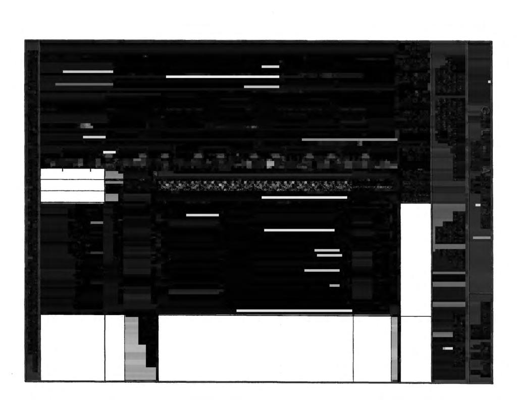

62
63
64
65 Gregg In Sit ic. Interpretation Output - Release. 00.9e Run No: Job No: SH Client: GEOLOGIC ASSOCIATES Project: CRT Site Investigation Site: LOS COYOTES Location: CPT- Engineer: K, McMILLEN CRT Date: 00/26/09 CPT Time: 2:33 CRT File: 784C.COR Northing (m): 0 Easting (m): 0 Elevation (m): 0 je: a Water Table (m): 8.53 (ft): 28.0 Su Nkt used: 2.50 Averaging Increment (m): 0.30 Phi Method : Robertson and Campanella, 983 Dr Method : State Parameter M: Jamiolkowski - All Sands.20 Used Unit Weights Assigned to Soil Zones Values of.0e9 or UnDef are printed for parameters that Depth (ft) AvgQt (tsf) AvgFs (tsf) AvgRf (%) AvgUd (ft) SBT u.wt. pcf are not TStress (tsf) valid for EStress (tsf) the material type Ueg (tsf) Cn (SBT) N60 (ND60 (blows/ft) Su (tsf) CRR UnDef 0.0 UnDef 0.0 UnDef 0.0 UnDef 0.0 UnDef UnDef UnDef UnDef UnDef UnDef UnDef UnDef UnDef UnDef UnDef UnDef UnDef UnDef UnDef UnDef UnDef UnDef UnDef 0.26 UnDef UnDef UnDef 0.3 UnDef UnDef 0.4 UnDef 0.8 UnDef 0.9 UnDef UnDef 0.2 UnDef 0.39 UnDef 0.39 UnDef 0.2 UnDef 0.2 UnDef 0.8 UnDef 0.25 UnDef UnDef UnDef UnDef UnDef UnDef UnDef UnDef 0.26 UnDef
66 Gregg In Situ, inc. Interpretation Output - Release. 00.9e Run No: Job No: SH Client: GEOLOGIC ASSOCIATES Project: CRT Site Investigation Site: LOS COYOTES Location: CPT- Engineer: K. McMILLEN CPT Date: 00/26/09 CPT Time: 2:33 CPT File: 784C.COR Northing (m): 0 Easting (m): 0 Elevation (m): 0 page: b Water Table (m): 8.53 (ft): 28.0 Su Nkt used: 2.50 Averaging Increment (m): 0.30 Phi Method : Robertson and Campanetla, 983 Dr Method : Jamiolkowski - All Sands State Parameter M:.20 Used Unit Weights Assigned to Soil Zones Values of.0e9 or UnDef are printed for parameters that are not valid for the material type (SBT) Depth (ft) k (cm/s) Bq Qtn Rfn SBTn QdN DeltaQdN QdNcs Fc Phi (%) (Deg) Dr ( /o) OCR State Del(n)60 Param (N)60cs E-5.0E-5.0E-5.0E-5.0E-5 5.0E E E E E E E E E E E E E E E E E E E E E E E E E E E E E E E E E E E E E UnDef UnDef UnDef UnDef UnDef UnDef UnDef UnDef UnDef UnDef UnDef.0 UnDef.0 UnDef.0 UnDef.0 UnDef UnDef UnDef 65.3 UnDef UnDef UnDef UnDef UnDef UnDef UnDef UnDef UnDef UnDef UnDef UnDef UnDef UnDef UnDef UnDef UnDef UnDef UnDef UnDef UnDef UnDef UnDef UnDef UnDef UnDef UnDef

67
68 -Sample No. «*^*«IC-».-*- '* SJC-<»^4 DENSI STS ^/SJC^^ ^SJKSWS*^ Job No _GM (LA San Districts) -pr«ub&ft? IKS3Pffi PfS. ssps#«l SSPll! No. Ring Soil Type L. Brown, F.C. Silty Sand w. Gravel Tan, F. Silty Sand Tan, F. Silty Sand Tan, F. M. Clayey Sand L. Brown, Clayey Silt Gray Brown, F. Silty Sand w. Gravel L. Brown, F.C. Sand w. Silt L. Brown, F. Sandy Silt Wet+Tare Tare Wet density % Water Dry Density No. Ring ik&^jajsiarijfs&imsjfcajhj: ^^tc-2/2'l.,i f'vccj/5 '?< !*? Ai&ii%ii r ^H^Uv-il/Bs!7«\* Soil Type Brown, F. Silty Sand Brown, F. Sandy Silt Brown, F. Silty Sand Gray, F. Clayey Sand Gray, F. Sand w. trace Silt Gray Brown, P.M. Sand w. Mica Gray Brown, F. Sand Gray Brown, F.M. Sand w. Mica Gray, F. Sandy Silt Gray, F. Silty Sand Wet+Tare Tare Wet density % Water Dry Density No. Ring I 96.8 i *' -,- - ' i ' ,itr * se 06.3.* V- kv 95. Tf 'N.".*" f> 97.8 JUiwj.Att"*W Soil Type Wet+Tare Tare Wet density % Water Dry Density
69 GRAIN SIZE AN, SIS - ASTM D 422 Project / Client GLA Job No Job No GLA Sample By No. SJC-/ 0-5' JK Date 9/28/00 Sieve Opening Weight mm Sieve Size % Passing Time D Temp. dr HYDROMETER R R+C KL d (mm) R+Ar % Pass " " " " 3/4" /2" 3/8" #4 #8 #6 #30 #50 # # TAVE.= Kn = Dry Weight (g) = Total Dry Weight #4Wet Weight 350 Water Content 2 -#4Dry Weight amec*
70 "-V GRAIN SIZE AN/ AS - ASTM D 422 Job No GLA U.S. Standard Sieve Size 2in in /2m #4 #6 #50 # Qf\ D) 70 0) g Kn to g 50 u. 40 u u0> Q [ j 3in I J 5m 3/4m 3/8in #8 #30 [ T P f i I, I,,! ' I ' t ' % i - L V ~r «, I -t- I *-^. T " I ~v T " "\. ^^^'X,^ i i- ">^ i II ^ ^ ~I ^ ^. s i I K- N.N # -T-- - -r T- ' [ t-7- j i \ : : ^ j I!... T ~"~ " ]-... i - " 0 A j : i Grain Size (mm) Sample Max. Dry Density (pcf) Opt. Water Content Expansion Index TestW.C.. Final W. C. Resistivity (ohm-cm) ph SO 4 (%) LL PL PI Unified Soil Class. GW Description GRAVEL - SAND MIXTURES
71 GRAIN SIZE ANA. ols - ASTM D 422 Project / Client GLA Sample By No. SJC-/5 JK (a) 5' Job No Date 9/28/00 Job No GLA Sieve Opening Weight mm Sieve Size 3" 2".5" " 3/4" /2" 3/8" #4 #8 #6 #30 #50 # #200 % Passing Time D TAVE= Kn - Temp. dt HYDROMETER R R+C Dry Weight (g) = KL d (mm) R+Ar % Pass Total Dry Weight - #4Wet Weight Water Content - #4Dry Weight 259.7
72 ' GRAIN SIZE AN/ AS - ASTM D 422 Job No GLA U.S. Standard Sieve Size 2in Tin /2m #4 #6 #50 # I 80 i ^ n 70 0) g >, 60 CD g 50 u. 4 0) a n 3m : > +, I -!- : - ;, -. i i i 4-. (i <!i ' j! > r '!.5in 3/4in 3/8in #8 #30 # n T r r " '; : *h ~. f. *-. ---, ^ ^- ^*~ '! ^ ^""-t I ~i T ~-i^, "" '-. L ' i " ',,, r ' : " -^ i - i j i a. " _ -I--] T...._ !-- - i i I! r i! ; - ^^. --- ' 4 : j-^ " i l 0 0 Grain Size (mm) i -f-fj "t T "^ i j ' ' "T" " j! -)- i ~ "'" \... " " - I - -- _. -.._.! P " " Sample Max. Dry Density (pcf) Opt. Water Content Expansion Index TestW.C.. Final W. C. Resistivity (ohm-cm) PH SO 4 (%) LL PL PI Unified Soil Class. Description 5' ML SANDY SILT
73 GRAIN SIZE AN/ IS - ASTM D 422 Project / Client Sample By No. GLA SJC-/7 JK (5)2' Job No Date 9/28/00 Job No GLA Sieve Opening Weight mm Sieve Size 3" 2".5" " 3/4" /2" 3/8" #4 #8 #6 #30 #50 # #200 % Passing Time D TAVE= Kn = Temp. dt r HYDROMETER R R+C Dry Weight (g) = KL d (mm) R+Ar % Pass Total Dry Weight - #4Wet Weight Water Content - #4Dry Weight 252.6
74 ' ' GRAIN SIZE ANA. JS - ASTM D 422 Job No GLA U.S. Standard Sieve Size 2m m /2in #4 #6 #50 #200 ^_, 3n. 90! 80 ra 70 '5 5 >, 60 i4 l i iz S 40 Q t. i t : i ; i IIj- Sin, 3/4in 3/8in #8 #30 # :- - i j i..- J_ i... i t i..;_._... -*-. ~i ~-. *** L_ N" \ \ s r., \' \ ' ' ^v i I 4 r -i -{- -! i! i - I I ri i ii T - - ~r ~r i r-( -[ r! ' i i 0 0 Grain Size (mm) -i ft i. i - i 0.0 Sample Max. Dry Density (pcf) Opt. Water Content Expansion Index TestW.C.. Final W. C. Resistivity (ohm-cm) ph O/^i 0 \ 0^4 \ /o ) LL PL PI Unified Soil Class. SM Description SILTYSAND
75 GRAIN SIZE AN/ jls - ASTM D 422 Project ;/ Client Sample By No. GLA SJC-/304 JK Job No Date 9/28/OQ Job No GLA Sieve Opening Weight mm Sieve Size 3" 2".5" " 3/4" /2" 3/8" #4 #8 #6 #30 #50 # #200 % Passing Time D TAVE= Kn = Temp. dt HYDROMETER R R+C Dry Weight (g) = KL d (mm) R+Ar % Pass Total Dry Weight - #4Wet Weight Water Content - #4Dry Weight a/nee
76 ] GRAIN SIZE ANA IS - ASTM D 422 Job No GLA U.S. Standard Sieve Size 2in m /2m 04 #6 #50 # >. 60 m c 50 iz g ) in 0 [ 3m.5m!! t:r V : : j i - i t - \ i i 'I H i : i \. i -, 3/4in 3/8in #8 T - *~ - - * " ' t - " 4 4. : i - r- -' ; : i t T ~~~ 4 H - ; - J -. i ( ;..; +_ - ;-- t - i, T- -4 t" 4- i _ # , ^- x N T- t : # --- t- - U- t-! i -f\ \, i. i ', Grain Size (mm) \ 0 : ' ' \ t* -l- -; -...I. - j. J -_.. i. - F L - -- "I - -r- Tff- - -I-,._! 0.0 Sample Max. Dry Opt. Water Expansion Density Content Index (pcf) (%) TestW.C.. Final W. C. Resistivity (ohm-cm) PH o/^ to/ \ ou 4 ( /a) LL PL PI Unified Soil Class. SM Description SILTYSAND
77 GRAIN SIZE ANA. JlS - ASTM D 422 Project / Client Sample By No. GLA SJC-/ 6(5)5' JK Job No Job Wo GLA Sieve Opening Weight mm Sieve Size 3" 2".5" " 3/4" /2" 3/8" #4 #8 #6 #30 #50 # #200 % Passing Time D TAVE= Kn = Temp. dr HYDROMETER R RtC Dry Weight (g) = KL d (mm) R+Ar % Pass Total Dry Weight - #4Wet Weight Water Content - #4Dry Weight 350
78 ' ' GRAIN SIZE ANA IS - ASTM D 422 Job No GLA U.S. Standard Sieve Size 2m tin /2in #4 #6 #50 #200 3m.5in 3/4m 3/8m,--,,, * * ra 70 0) >, OQ 60 I 50 g 40 V o! I:... K i '.. i i ; i i,'![ ' I I [ i '. i; ; _;_ ^ I.!! J!. L.. \L 0! ' i.. i i - #8 #30 - I j---' -, " "~ t i 4, L.._,..;. _._ i i! - - l~ \ I T i Grain Size (mm) f # ^ ' " tt 4 - r - 0 ;. - f-~ I'- ; "i -H "t " i - -- j ' T " " r t ;! i h -._ Sample Max. Dry Opt. Water Density Content (pcf) (%) Expansion Index Test W.C.. Final W. C. Resistivity (ohm-cm) PH C*f~\ /O/ \ olj 4 ( /o) LL 44 PL 26 PI 8 Unified Soil Class. CL Description SILTYCLAY
79 GRAIN SIZE AN> AS - ASTM D 422 Project,/Client Sample No. By GLA SJC-2/9 (3)35' JK Job No Job No GLA Sieve Opening Weight mm Sieve Size 3" 2".5" " 3/4" /2" 3/8" #4 #8 #6 #30 #50 # #200 % Passing Time D TAVE= Kn = Temp. dt HYDROMETER R R+C Dry Weight (g) = KL d (mm) R+Ar % Pass Total Dry Weight - #4Wet Weight Water Content - #4Dry Weight 367.
80 GRAIN SIZE ANA. is - ASTM D 422 Job No GLA U.S. Standard Sieve Size 2m tin /2in #4 #6 #50 # on o> 70 "5 > >, 60 m 50 U.! I 40 j o o! 30 OA 0 0 _ 3m [-, il --4 i.5m 3/4in 3/8in #8 l T --T- r r - Ij ;. ; ' i t,, -i- 0 ^> - "V X N s. _ I. I.. H U -^ i I -- \. V X ; I. "--' H- #30 # T --; -..i:. i... > s,. ^j- ; PS X ^. J...! 0 Grain Size (mm) [ i r ji - I - i - t r r T'-r-i i i -- i ^ ] - ] -J L Sample Max. Dry Density (pcf) Opt. Water Content Expansion Index TestW.C.. Final W. C. Resistivity (ohm-cm) PH SO 4 (%) LL PL PI Unified Soil Class. GW Description GRAVEL-SAND MIXTURES
81 GRAIN SIZE AN/ AS - ASTM D 422 Project i' Client Sample No. By GLA SJC-2/ JK Job No Job No GLA Sieve Opening Weight mm Sieve Size 3" 2".5" " 3/4" /2" 3/8" #4 #8 #6 #30 #50 # #200 % Passing Time D TAVE= Kn = Temp. di HYDROMETER R R+C Dry Weight (g) = KL d (mm) R+Ar % Pass Total Dry Weight - #4Wet Weight Water Content - #4Dry Weight 300
82 GRAIN SIZE AN/ IS - ASTM D 422 Job No GLA U.S. Standard Sieve Size 2m m /2m #4 #6 #50 # in.5m 3/4in 3/8in #8 #30 " ; ; j, --- i # ^-, r i - I.._ ~\ on o> 70 I 60 m 50 < : - i i i i ' '...- i "T I \ I i..... i.. n JH...j_ i i I 40 o o Q , ; i",[ i J i ' i "i ' ', ' \ i. i, j i -- -T i ' i._ j, 0 -- L- r i I Grain Size (mm) - r Ij 0. H- 4 I - t - - -Ir - _...{. : i..l _ 0.0 L -. _ Sample Max. Dry Density (pcf) Opt. Water Content Expansion Index TestW.C.. Final W. C. Resistivity (ohm-cm) ph O/-N /O/ \ OU4 ( /o) LL PL PI Unified Soil Class. Description SJC-2/ CL SILTYCLAY a/nec
83 GRAIN SIZE ANA,IS - ASTM D 422 Project / Client Sample No. By GLA SJC-2/3O5 JK Job No Date 9/28/00 Job No GLA Sieve Opening Weight mm Sieve Size 3" 2".5" " 3/4" /2" 3/8" #4 #8 #6 #30 #50 # #200 % Passing Time D TAVE= Kn = Temp. dr HYDROMETER R R+C Dry Weight (g) = KL d (mm) R+Ar % Pass Total Dry Weight - #4Wet Weight Water Content - #4Dry Weight 343.6
84 GRAIN SIZE ANA,IS - ASTM D 422 Job Wo GLA U.S. Standard Sieve Size 2in tin /2m #4 #6 #50 #200 Sin i.sin 3/4in 3/8in #8 #30 # 90 r i-i ;! - T ' ~ _ r. > S ^y i o> 70 > >, 60 DO. **" 50 I -{ o 40 I ffi Q- 30 on 0 - -J - \ j I t,, - t -- - i ; i it!! I i I '- i t i. i i """F" t I -,- - --; r '- ' i "" i -- -i -, - '^ r- -- r. i.^ 4- T" :T -- i, r, - It - t ii - i "" - - ' \»- 4 \ \ \ ' T j ; \^ '^v~ _j 4 -i -«r ' T - - t! i I -i i i i r i 0 Grain Size (mm) Sample SJC-2/3 Si- Max. Dry Density (pcf) Opt. Water Content Expansion Index TestW.C.. Final W. C. Resistivity (ohm-cm) PH c/*^\ (o/ \ OV_>4 ( /o) LL 29 PL 23 PI 6 Unified Soil Class. ML Description SANDY SILT
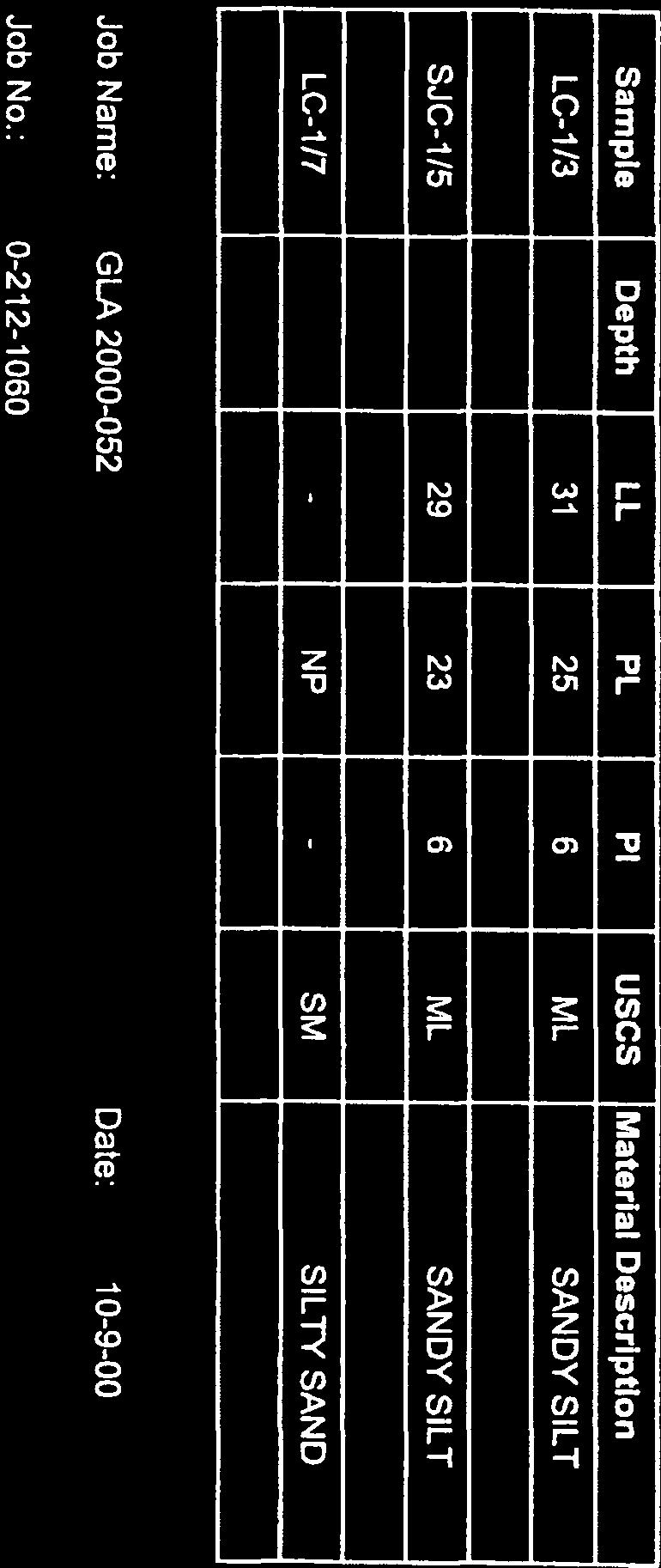
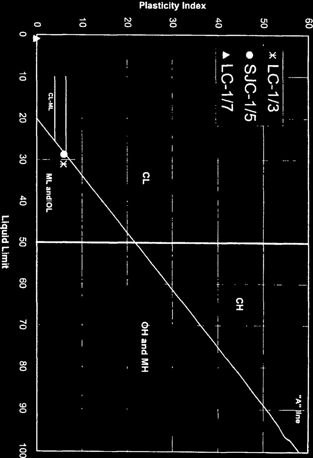
85

86


87
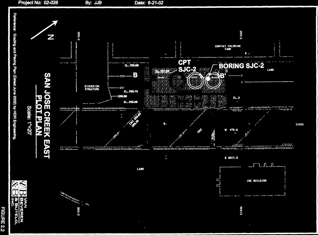
88


89

90
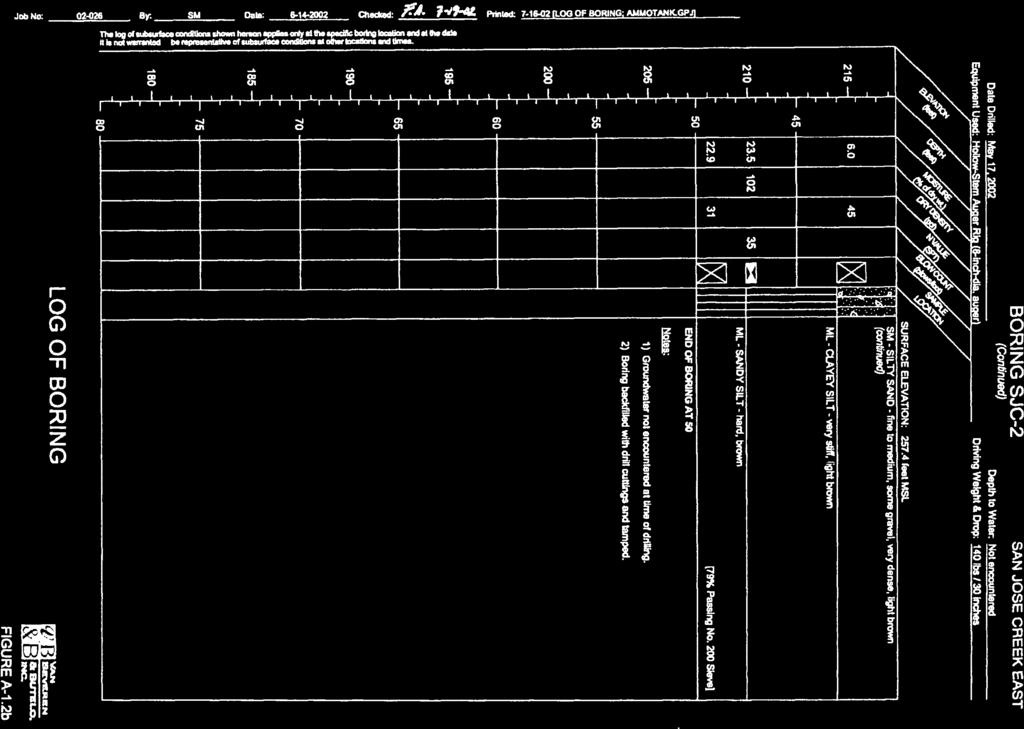
91
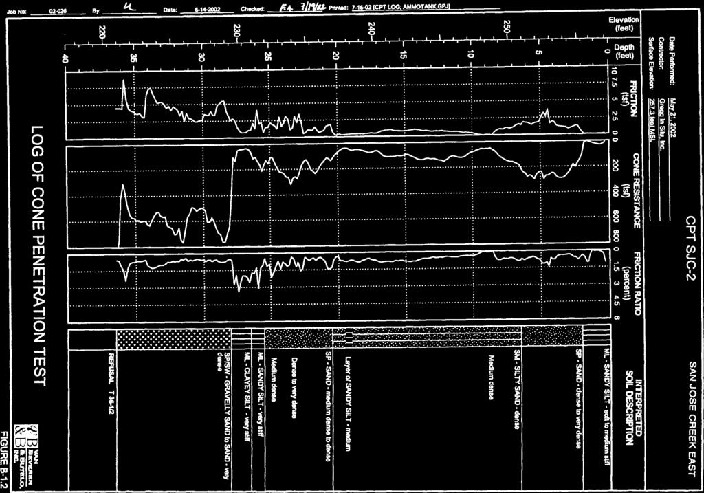
92

93
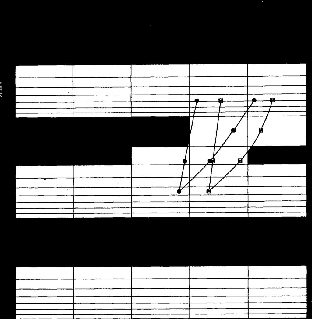

94

95

96


97

98
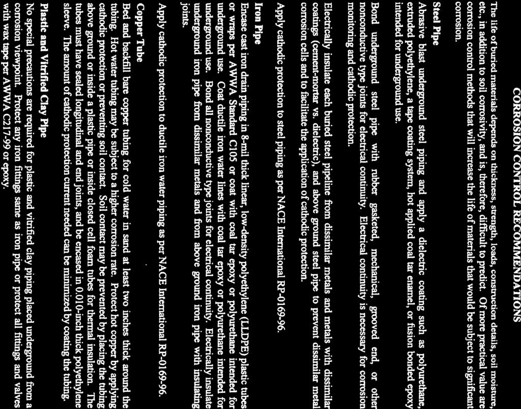

99

100


101

102

103
104


105


106

107

108

109


110


111

112


113


114


115


116