Walter E. Deuchler Associates, Inc. Consulting Engineers
|
|
|
- Lorena Richardson
- 5 years ago
- Views:
Transcription
1 I. DESCRIPTION OF PROJECT HIGHLIGHTS

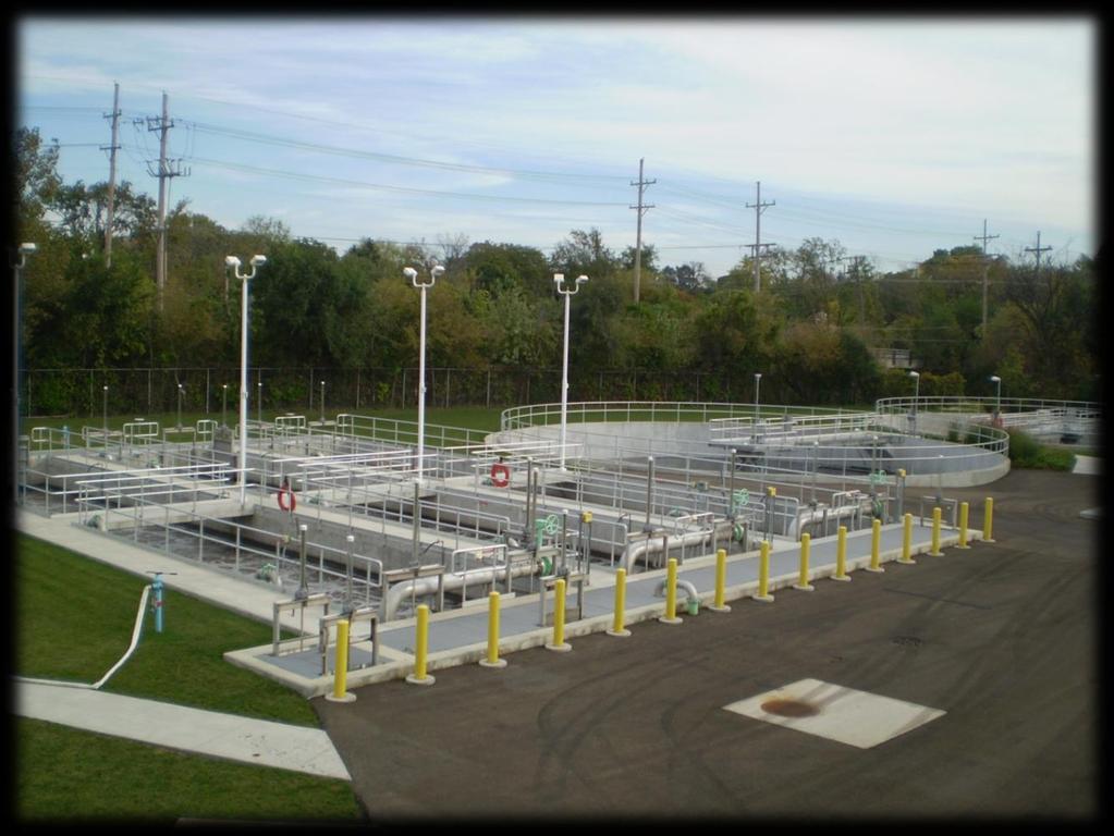
2 P lanning for the latest improvements to the Salt Creek Sanitary District (District) began in 2001 with the updating of the Facility Plan, which identified the need for the District to improve nitrification and clarification capabilities. The project included 0.5 MG of additional aeration volume in a new, three pass aeration battery and two final clarifiers. The project also included a secondary control building to house MLSS splitting valves, RAS pumps, final clarifier effluent pumps, scum and drainage pumps, electrical gear, controls, SCADA and a new laboratory. The proximity of the plant to neighbors NEW AERATION BATTERY on the east side of Salt Creek was of concern to the District. To reduce potential dangers, the District elected to use ultraviolet disinfection. The project was bid in February 2004 and was completed in February 2006 for $7.15 million. The plant has been operating exceptionally well with BOD and ammonia concentrations often at nondetect levels.
3 II. ROLE OF ENTRANT S FIRM IN PROJECT

4 W alter E. Deuchler Associates, Inc. (WEDA) provided overall project management of the design of the proposed civil, structural, process, and mechanical components of the design. Illinois Hydraulic Company of Elgin, Illinois was awarded the project and began construction in May WEDA provided construction inspection services, shop drawing review, and served as the Owner s Representative throughout construction.
5 III. EXPLANATION OF HOW THE PROJECT MEETS EACH OF THE RATING GUIDELINES

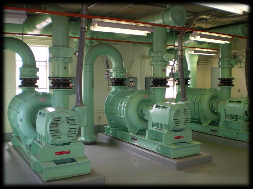
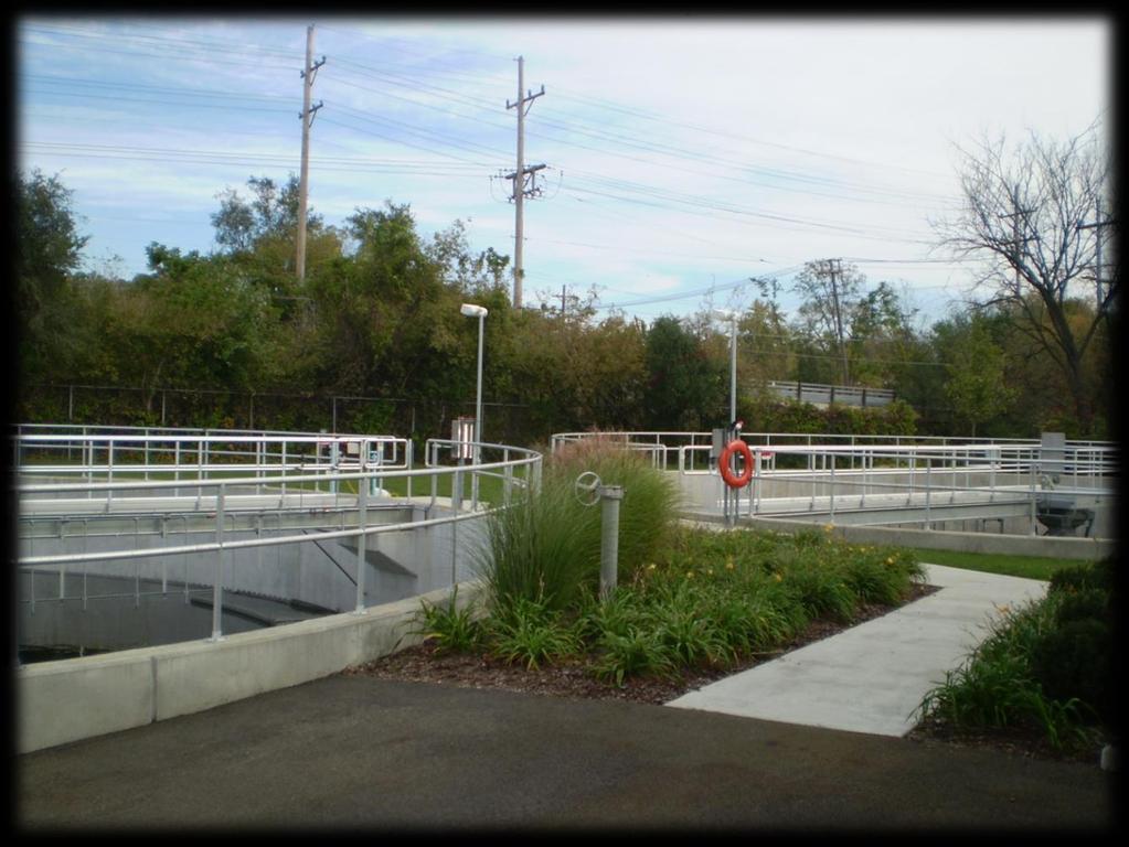
6 A. Original or Innovative Application of New or Existing Technique T he improvements project was undertaken to improve the nitrification ability of the treatment plant. The existing aeration tanks were single pass tanks providing approximately 1 million gallons of aeration volume. The tanks were designed originally with coarse bubble diffusers, that were subsequently changed to fine-bubble diffusers in the 1990 s. At the time the diffusers were changed, the blowers were not, and because of the pressure limitations of the existing blowers, the diffusers had to be placed 2.5 feet from the finished floor. Site limitations in the past also forced the District to use square final clarifiers with corner sweeps. When the 2004 Improvements Project was undertaken, it was determined to improve nitrification by adding 0.5 million gallons of aeration volume. The existing 3 centrifugal blowers were retrofitted with two additional stages to allow the existing diffusers and new diffusers to be set approximately 9 inches above the finished floor providing for both better mixing and greater oxygen transfer efficiency. The new and existing aeration tanks were designed to operate in parallel or as a multipass system. The multi-pass system insures more even mixing and more reliable treatment. New 14 foot deep, circular final clarifiers were designed with rapid sludge removal headers, energy dissipating inlets, spray bars, Stamford baffles, and algae sweeps. The clarifiers have been operating
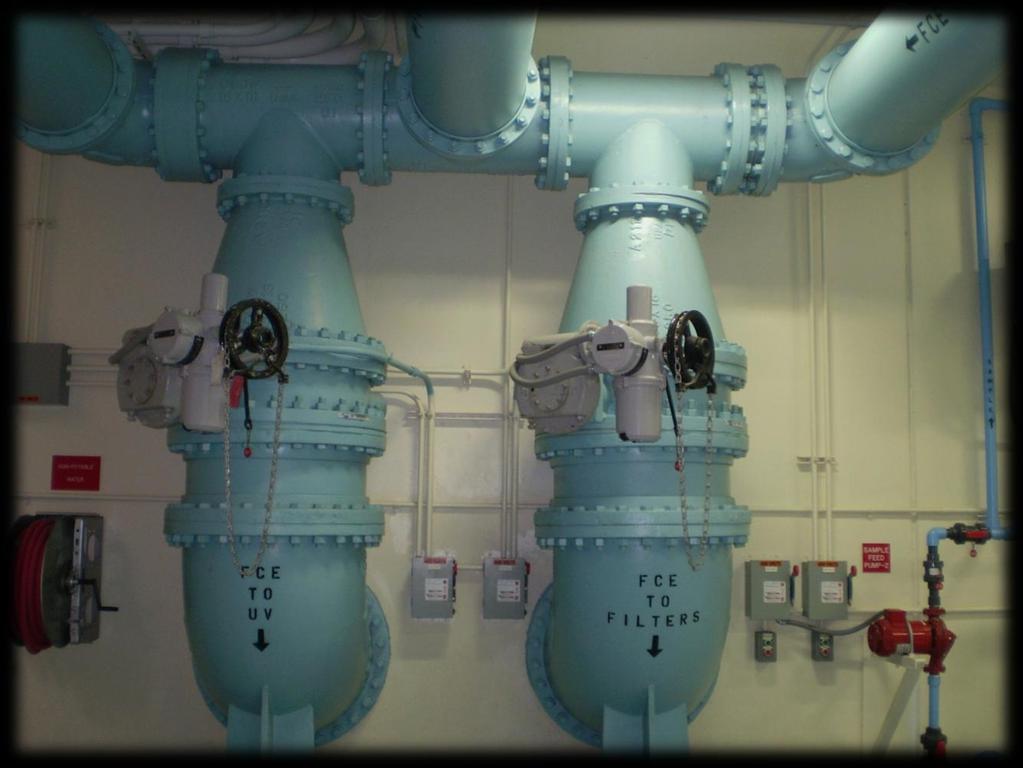
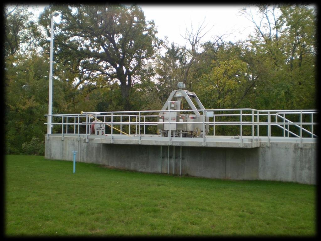
7 exceptionally well. As a result the operators, can bypass the filters and effluent can be pumped directly to the UV system. The RAS pumping system was designed so a pump may be dedicated to each clarifier. Homes are in close proximity to the treatment plant, therefore, in the planning stages UV disinfection was considered and implemented as part of the 2004 Improvements Project. The UV system, Trojan 4000+, was selected because of its ability to treat under radically different tail water conditions which are influenced by the flood stage of Salt Creek. The heart of the process is the new secondary control building which houses the MLSS splitting valves to the finals, the RAS pumps, the WAS valve, the Final Clarifier Effluent pumps, the scum and drainage pumps, a laboratory, and electrical control room. Instrumentation in strategic locations was provided and a dual fiber optic network and SCADA system allows the operators to closely monitor the process.

8 B. Future Value to the Engineering Profession and Perception by the Public T he Salt Creek Sanitary District was not under Consent Decree or mandated by the IEPA to undertake the 2004 Improvements Project. However, the Board of Trustees of the District recognized the need for investing in new infrastructure to replace existing infrastructure while also providing the latest technology ultimately reducing the possibility for effluent excursions. The District was recognized by the Village of Villa Park Environmental Concerns Commission for undertaking the project to improve the water quality of Salt Creek for today s generation as well as future generations. C. Social, Economic and Sustainable Design Considerations T he District saw a need to replace aging infrastructure, and to provide new systems that would provide for process flexibility and most importantly, process reliability. Salt Creek meanders through a number of heavily developed suburban communities. The water quality of the Creek in the past has suffered from the effects of CSO s, non-point source pollution, as well as discharges from treatment plants. By voting to undertake this project, the Board of the Salt Creek Sanitary District, made a bold statement that the District and the citizens it serves were committed to improving the water quality of Salt Creek. Through the process of working with staff in the development of the Memorandum of Design, the District staff selected equipment and processes that would provide for great reliability
9 and also be environmentally friendly. For example, UV disinfection was selected to eliminate the possibility of a gas leak that could harm the public, and to eliminate the possibility of a high chlorine residual that could harm aquatic life. D. Complexity T he greatest challenge in the design was the small footprint available, and the existing hydraulic constraints. The existing plant dates to the early part of the 20 th century. As a result, much of the plant has been constructed over and around existing infrastructure. Adding to the complexity, was the fact that a new aeration battery had to be fit into the existing hydraulic grade line. The four existing single pass aeration tanks that flowed to the south were converted to multipass tanks ultimately flowing to the north--- the only location where new facilities could be constructed. The existing plant had very little instrumentation for process control. The new facility has a state of the art SCADA system using Rockwell Automations Control-Logix platform. The SCADA system controls the mixed liquor split to the final clarifiers to maintain a balance, the RAS rate to pace with the influent flow, and wasting on a schedule to meet a target volume calculated by the SCADA system. Dissolved oxygen probes in combination with thermal mass flow meters are used to indicate the viability of the biomass. Historical trending and data logging was also included as part of the SCADA system and is a valuable tool in the hands of the operations staff.
10 E. Exceeding Client/Owner Needs D esign of the 2004 Improvements Project began in March 2003, with a submittal to IEPA at the end of October revolving loan funds. This ambitious schedule was required in order to secure state maintained all the design milestones set forth in the Memorandum of Design to insure that the ultimate goal of bidding in February 2004 was met. Through out the design process options were presented and opinions were solicited from the operations and maintenance staff so at the end of the project the operator s had a plant with flexibility and equipment that could be maintained, ultimately resulting in a plant that is reliable.
11 IV. PHOTOS
12
13
14
15
16
17