Concentrated Solar Thermal Power Technology
|
|
|
- Esmond Martin
- 5 years ago
- Views:
Transcription
1 Concentrated Solar Thermal Power Technology Prof. G.R. Tynan MANY SLIDES ADOPTED FROM A TALK AT 2005 AAAS MEETING BY E. BOES, NREL And Professor Carlos Coimbra, UCSD-MAE & CER

2 Three Main Solar Thermal Electric System Architectures IEA, Solar Thermal Power Technology Roadmap, 2014

 (b) Dish/Engine")
 (c) Power Tower")
3 (a) Three Main Solar Thermal Electric System Architectures Trough Technology (Bulk Power) (b) Dish/Engine Technology (Distributed Power) (c) Power Tower Technology (Bulk Power)
4 Utility Scale Central Plants California Valley Solar Ranch, 250 MW Single-Axis Tracking 4

5 Concentrating Parabolic Trough Technology

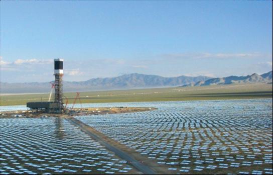
6 Heliostat Array & Power Tower Ivanpah Solar Electric Generation System,

7 System schematic
8 Schematic of Solar Thermal Plant P in =I 0 A, P aux w/ Thermal Storage Storage Tank ρ,c p,v,t dq out /dt Pump Working Fluid Turbine P out = dw/dt Heat XChng dq waste /dt (to water or air) Energy Balance at Storage Tank Gives ρc p V T t Energy Balance at Turbine Gives = P in + P aux dq out dt dq out dt = dw dt + dq waste dt
9 Analysis of Solar Thermal Heat Balance- Steady-state Day Operation Add two together & use def n of P out dq out dt thus = P out + dq waste dt ρc p V T t = P in + P aux 1 η th P out ; P out = dw / dt; W = η th Q out With Solar Input Only Then Have ρc p V T t = P in + P aux 1 dw η th dt P in = 1 dw η th dt in S.S. Steady-state!
10 Analysis of Solar Thermal Heat Balance- Transient Night Operation At Night Have No Power Input P in = 0 & P aux = 0 Transient Heat Balance Gives ρc p V T t = 1 dw η th dt If Have Expontial Like Decay, T~e -t/τ ρc p V T τ = 1 dw η th dt τ = ρc p VTη th dw / dt
11 Transient Night Operation of Solar Thermal Plant Key Conclusion: Can make Power at Night IF V large enough and/or dw/dt Small Enough τ = ρc p VTη th dw / dt > 24hours Adding P aux (e.g. from Gas Fired Heat Input) Allows Additional Backup Capability

12 Thermal Storage Enables Dispatchability; Load Shifting IEA, Solar Thermal Power Technology Roadmap, 2014
13 Three types of solar irradiation Direct normal incidence (DNI): intensity of unscattered light coming directly from sun, normal to a surface Diffusive horizontal incidence (DHI): intensity of scattered irradiation incident on a horizonal surface Global horizontal irradiance (GHI): DHI + direct irradiance to a horizontal surface
")
 Diffuse")

14 Difference between direct normal irradiance (DNI) and global horizontal irradiance (GHI) Diffuse Zenith angle q z Direct GHI ~ Direct*cos q z + Diffuse
15 Concentrated Solar Power (CSP) Requires direct-beam solar radiation (more in a moment) Uses familiar components & technologies glass, steel, gears, heat exchangers, turbines Can provide dispatchable power IF: Thermal storage is incorporated, or Hybridized with natural gas
16 Clouds, Dust & Aerosols Act to Scatter Solar Radiation è Reduced DNI Scattering events Incident, unscattered light Scattered radiation Transmitted Unscattered rays Clouds, aerosols, dust


17 Clouds, Dust & Aerosols Act to Scatter Solar Radiation è Reduced DNI


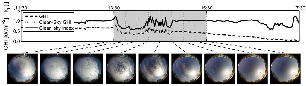
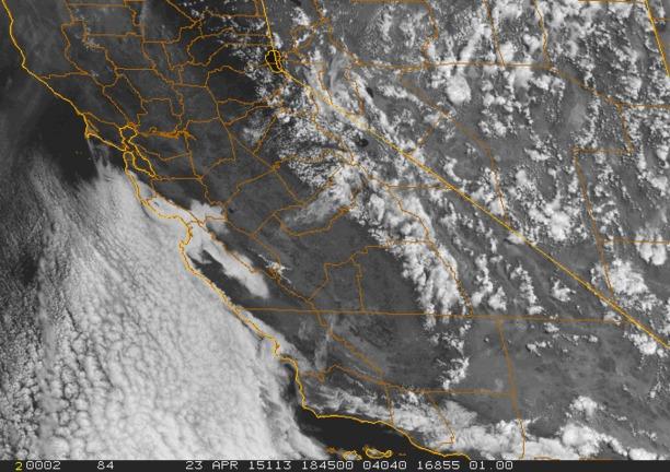
18 Effect of clouds on solar irradiance at the ground level
19 Review Specular Reflection, Focusing Optics Acceptance Angle and Radiation Scattering
20
21
22
23
24
25
26
27
28
29
30
31
32

33 Require adequate DNI for CSP IEA, Solar Thermal Power Technology Roadmap, 2014

34 CSP Systems only use DNI è Only some regions are suitable Q: Where are the good sites? Where are the demand centers?

35 Sample Locations in the CONUS Merced, California Latitude: Longitude: Altitude: 65m San Diego, California Latitude: Longitude: Altitude: 104m Las Cruces, New Mexico Latitude: Longitude: Altitude: 1219m
36 Merced Summer GHI Maximum Winter GHI Maximum
37 San Diego Summer GHI Maximum Winter GHI Maximum
38 Las Cruces Summer GHI Maximum Winter GHI Maximum


39 Solar and Wind Forecasting for Large Power Plants Prof. Carlos F. M. Coimbra UCSD MAE/CER

40 1 100% Connected to Power Grid Since 2014

41 Utility Scale Central Plants Ivanpah Solar Energy Generation Systems, 392 MW


42 Concentrated Solar Towers SOLAR RECEIVER STEAM GENERATOR Concentrated sunlight converts water in a boiler to high-temperature steam. AIR-COOLED CONDENSER Environmentally friendly in design, using 95% less water than competitive technologies. OPTIMIZATION / CONTROL SOFTWARE Solar Field Integrated Control System is the proprietary optimization software to manage heliostat positioning and optimize concentrated sunlight on the boiler. TURBINE Steam powers turbine to produce electricity then is converted back to water through an air-cooled condenser. HELIOSTATS Software-controlled field of mirrors concentrate sunlight on a boiler mounted on a central tower.

43 Evolution of Installed Base - CSP IEA, Solar Thermal Power Technology Roadmap, 2014
44 SEGS Plant Experience (KJ) 400 O&M Costs vs. Production Kramer Junction SEGS 22 Kramer Junction Operational Experience Electrical Output Gross Solar Production - GWh Net Production O&M Costs - M$ O&M Costs - M$ Solar Production - GWh Kramer Junction SEGS Solar Prodution Solar Production DNI DNI - % O&M costs have dropped sharply over time, coincident with performance gains. These plants, placed in operation from 1987 through 1989, set many performance records in the 1990s. Using 25% energy input from natural gas via a supplemental boiler, capacity factors during SCE on-peak operation have exceeded100% for more than a decade (with >85% from solar operation).
45 Sargent & Lundy Cost Analysis 0.30 Cost reductions from Plant Scale Up Technology Development Volume Production LCOE 2002$/kWh MW SEGS MW SEGS MW SEGS Current Potential 2004 Technology, 50-MWe Size Future Cost Potential Factors Contributing to Cost Reduction - Scale-up 37% - Volume Production 27% - Technology Development Cumulative Installed Capacity (MWe) * Sargent and Lundy (2003). Assessment of Parabolic Trough and Power Tower Solar Technology Cost and Performance Impacts.
46 Solar Thermal Power System Plans Mojave Solar Park, USA California, 553MW, parabolic trough design[2] Pisgah, USA California near Pisgah north of I-40, 500MW, dish design[3] Ivanpah Solar, USA California, 400MW, power tower design[4] Unnamed, USA Florida, 300MW, Fresnel reflector design[5] Imperial Valley, USA California, 300MW, dish design[6] Solana, USA Arizona southwest of Phoenix, 280MW, parabolic trough design[7] Negev Desert, Israel, 250MW, design will be known after tender[8] Carrizo Energy Solar Farm, USA California near San Luis Obispo, 177MW, Fresnel reflector design[9] Uppington, South Africa, 100MW, power tower design[10] Shams, Abu Dhabi Madinat Zayad, 100MW, parabolic through design[11] Yazd Plant, Iran, 67MW steam input for hybrid gas plant, technology unknown.[12] Barstow, USA California, 59MW with heat storage and back-up, parabolic trough design[13] Victorville 2 Hybrid Power Project, 50MW steam input for hybrid gas plant, parabolic trough design[14] Kuraymat Plant, Egypt, 40MW steam input for a gas powered plant, parabolic trough design[15][16] Beni Mathar Plant, Morocco, 30MW steam input for a gas powered plant, technology unknown[17] Hassi R'mel, Algeria, 25MW steam input for gas powered plant, parabolic trough design[18] Cloncurry solar power station, Australia, 10MW with heat storage, power tower design[19] Source:
47 Solar Thermal Power Technology Achievements and Status 350 MW of parabolic trough plants built around 1990 still operating well Several power tower demonstration plants have established technology viability. Several dish systems have also operated successfully Engineering cost analyses indicate 5 cents/kwh achievable Likely Advances There are major opportunities for technology advances, in Collectors Power conversion Thermal storage Several new systems will be built within 5 years Their success should catalyze manufacturing advances, commercialization