Membrane Bioreactor and High Flow Biological Treatment System for the Cox Creek WRF
|
|
|
- Sandra Underwood
- 5 years ago
- Views:
Transcription

1 Membrane Bioreactor and High Flow Biological Treatment System for the Cox Creek WRF Thor Young, GHD With Contributions from Vince Maillard, Rip Copithorn, Kristi Perri, and Jeff Sturdevant, GHD Dimitrios Katehis and Scott Weikert, CH2MHill Mike Bonk and Chris Phipps, Anne Arundel County Joe Zorica, Heery International Copyright GHD 2010 October 27, 2010
2 Cox Creek Water Reclamation Facility (WRF) Owned and operated by Anne Arundel County, Maryland Serves the Baltimore suburbs in the north central portion of the County Discharge to Patapsco River (tributary of Chesapeake Bay)
3 Facility History 1955: 5.0 mgd primary treatment facility constructed at current site 1970: Facility upgraded to secondary treatment (activated sludge) and expanded to 8.5 mgd 1982: Facility expanded to 15.0 mgd


4 Cox Creek WRF 1982 Plant Flow Schematic
5 Nutrient Removal History Original activated sludge plant was designed for secondary BOD and TSS removal only (no nitrification) Ferrous sulfide addition to primary clarifiers started in mid- 1980s with effluent limit of 2.0 mg/l TP In 1990s, MDE approached Anne Arundel County about entering a voluntary agreement to implement biological nitrogen removal (BNR) at the facility in exchange for grant funding The County decided to replace the surface aerators with fine bubble diffusers and convert into an MLE process in the existing reactors
6 BNR Upgrade (completed 2002) Seasonal TN Goal (8 mg/l May 1 Oct 31) MLE configuration Flexibility to operate w/ Step Feed During high flows from I&I When one activated sludge tank is out of service Primary Effluent From Junction Box Influent Pipe (typ) Flexibility to increase aerobic volume and MCRT Cyclic aeration of anoxic zone Helps re-establish complete nitrification quickly Effluent Channel Nitrate Recycle Nitrate Recycle Aerobic Zones Anoxic Zones Influent Channel Nitrate Recycle Nitrate Recycle Nitrate Recycle Nitrate Recycle Nitrate Recycle Copyright GHD 2009 To Secondary Clarifier Distribution Box through 2 48 pipes
7 BNR Performance Since 2002, BNR facility has been able to achieve annual average TN as low as 8 mg/l Example: 2006 Annual Average at ADF of 11.9 mgd NH4-N: 0.7 mg/l Organic-N: 1.3 mg/l TKN: 2.0 mg/l NOx-N: 5.3 mg/l TN: 7.3 mg/l TP: 1.1 mg/l However, clarifier performance limitations prevented complete nitrification under cold weather conditions


8 Clarifier Performance Limited Winter Nitrification Final Clarifier Limitations Max MLSS = 3,000 mg/l / SOR = 300 gpd/sf If MLSS >, then RAS plugs loose clarifier 15 to 25 mg/l effluent BOD and TSS with solids settling in Chlorine Contact tanks Poor seasonal SVI Polymer required
9 Historical Plant Performance Loss of nitrification during cold weather conditions Oct-02 Dec-02 Feb-03 Apr-03 Jun-03 Aug-03 Oct-03 Dec-03 Feb-04 Apr-04 Jun-04 Aug-04 Oct-04 Dec-04 Feb-05 Apr-05 Jun-05 Concentration (mg/l) or Temperature ( C) Aug-05 Oct-05 Dec-05 Feb-06 Apr-06 Jun-06 Aug-06 Month Effluent Ammonia Temperature Copyright GHD 2009

10 ENR Upgrade MDE s ENR Program required upgrade to 3 mg/l TN and 0.3 mg/l TP at all 66 major municipal WWTPs in the State. Anne Arundel County designated Cox Creek as the first of their 7 plants to be upgraded for ENR because it had the higher current nutrient loading and most to gain from ENR


11 ENR Design Criteria Average Daily Flow: 15.0 mgd Maximum Month Flow: 19.4 mgd Peak Hour Flow: 45.0 mgd Accommodate peak hour without equalization ENR Limits (1) < 4 mg/l TN annual average < 3 mg/l TN May-October average < 0.3 mg/l TP annual average Note 1. Actual ENR Limits in the County s draft watershed permit are based on an annual average discharge equivalent to 4.0 mg/l TN and 0.3 mg/l TP at the MDE approved design capacity for each of five (5) County-operated WRFs in the watershed, including the Cox Creek WRF.

")
12 Technical Issues Limited space available for new construction Power Line Right-of-Way Constellation Energy (BGE) Property Wetlands Cox Creek
13 ENR Process Selection Procedure Develop ENR Evaluation Matrix Develop 5 general ENR categories to include all application ENR processes Use Evaluation Matrix to complete Initial ENR Screening to shortlist down to 3 general ENR categories Develop multiple ENR alternatives for each general ENR category Use ENR Evaluation Matrix to select one ENR alternative to evaluate from each general ENR category Develop a preliminary design, site plan, and cost estimate for selected ENR alternative Make final ENR Process selection based on capital and O&M cost estimates as well as non-cost criteria


14 Top 3 ENR Alternatives Alternative A: Single-Stage Activated Sludge Process Alternative B: Parallel Suspended Growth Process Alternative C: Single-Stage MBR
15 Alternative A: IFAS with Effluent Filters Nitrate Recycle Supplemental Carbon Metal Coagulant Secondary Clarifiers Effluent Filters Primary Effluent Anoxic Aerobic Anoxic Aerobic Intermediate Pump Return Sludge Station To Disinfection Modify the existing BNR reactors and construct one additional reactor to create four (4) two-pass IFAS nitrification tanks Build new pre-anoxic, post-anoxic and reaeration tanks at the site of the existing Maintenance Building to create 4-Stage Bardenpho process Build new 125-ft secondary clarifier Construct deep-bed sand filters


16 Alternative A: IFAS with Effluent Filtration Sodium Hypochlorite Feed Facility Methanol Feed Facility Ferric Chloride Feed Facility Relocated Maintenance Building Parking Filter / Electrical Building Filter Backwash PS Pre-Anoxic Zone PE/RAS DB Post- Anoxic Zone Reaeration Blower Building Modifications to SCDB Effluent Filters Secondary Clarifier Effluent PS IFAS Nitrification Tanks 8 th Aeration Tank 125-ft Secondary Clarifier

17 Alternative B: Parallel Train Oxidation Ditches Supplemental Carbon Metal Coagulant Return Sludge Nitrate Recycle Post- Anoxic Aerobic Supplemental Carbon Metal Coagulant Secondary Clarifiers Primary Effluent Anoxic Aerobic Anoxic Aerobic Return Sludge 4-Stage Bardenpho Tanks Intermediate Existing Pump Secondary Station Clarifiers Effluent Filters To Disinfection De-rate existing facility to 7.5 mgd, modify the existing Bardenpho and construct one (1) additional reactor to create four (4) two-pass 4-Stage Bardenpho tanks Construct a new pump station to convey primary effluent to oxidation ditches Construct parallel oxidation ditches, post-anoxic and reaeration tanks and secondary clarifiers Construct a new secondary clarifier effluent pump station Construct deep-bed sand filters


18 Alternative B: Parallel (Partial Site Plan) Sodium Hypochlorite Feed Facility Methanol Feed Facility Ferric Chloride Feed Facility Filter / Electrical Building Filter Backwash PS ENR Process Tanks Effluent Filters Secondary Clarifier Effluent PS PE/RAS DB/PS 8 th Aeraton Tiank
19 Alternative B: Overall Site Plan Blower Building High-Voltage Right-Of-Way New Plant Entrance Oxidation Ditches Post-Anoxic & Reaeration Tanks Secondary Clarifier RAS Pump Station
20 Alternative C: Membrane Bioreactor Primary Effluent Pre-Anoxic Nitrate Recycle Aerobic Supplemental Carbon Post-Anoxic Metal Coagulant Membranes Permeate Pump To Disinfection MLSS Recycle Recycle Pump Modify the existing BNR reactors and construct one (1) additional reactor to create four (4) two-pass modified Bardenpho tanks Construct new membrane tanks and building for membrane process equipment


21 Alternative C: MBR Site Plan Sodium Hypochlorite Feed Facility Methanol Feed Facility Ferric Chloride Feed Facility Relocated Maintenance Building PE/RAS DB Fine Screens Parking MBR Facility 8 th Aeration Tank ENR Process Tanks
22 Cost Evaluation Estimated capital cost and 20-year present worth cost of required O&M for each Alternative. Alternative C had the lowest capital cost and 20-year total present worth cost. 1.2 Non Cost Factors Alternatives B and C have very similar non-cost criteria scores Relative Cost A B C Alternative Capital Cost 20 Year PW O&M Cost
23 Other Decision Factors Favoring MBR Recovers space on existing site for future needs Potential for meeting future regulatory requirements Increased potential for water reuse Sludge settleability is no longer a limiting factor One compact process for all TN & TP removal No schedule risk associated with land purchase


24 Cox Creek WRF: ENR Process Selection Alternative C: MBR Lowest Capital Cost Lowest Present Worth Cost Most effective use of existing site
25 Membrane Facility Location Initial ENR Evaluation was based on relocating existing Maintenance Building to build the new Membrane Facility. Upon more detailed evaluation, this location had several disadvantages: Requires demolition and relocation of 15 year of Maintenance Building Site provides very limited space for building and equipment access Site would require significant construction in Chesapeake Bay tidal wetlands buffers Concern that some membrane suppliers may not be able to fit their system in this footprint (decreases competition)
26 Alternative Membrane Facility Location Alternative Membrane Facility Locations considered included: At location of existing circular primary clarifiers At location of existing stormwater management structure and dewatering truck scale Preliminary layouts and construction costs were done for each alternative

27 Alternative Membrane Location 2 Required relocation of primary clarifier capacity

28 Alternative Membrane Location 3 Significant site, piping, and stormwater costs
29 Membrane Facility Location 2 Selected Much less yard piping and utility relocation than Alt. 3 Enough space and good accessibility for alternative membrane designs (unlike Alt. 1) Closer to reactors more operator friendly location than Alt. 3 Least impact into wetlands and Critical Area buffers Least impact on site stormwater management Lowest construction cost
30 High Flow Management Strategy Initial ENR Evaluation was based on sending entire 45 mgd peak flow through MBR process Upon more detailed evaluation, the 3:1 extended peak flow condition was dictating membrane sizing (instead of maximum month flows and loads) Alternatives were sought to reduce capital and operating costs
31 MBR Design Criteria for Initial ENR Evaluation Peak Wet Weather Flow Drives the Sizing/Design of the Membrane Facility ORIGINAL DESIGN FLOW CONDITIONS Rated Capacity, mgd (Nominal) Average Daily Flow with recycles, mgd Maximum Monthly Flow with recycles, mgd FLOW RATE Peak Hour Flow with recycles, mgd 45.7
32 Alternative Approach with High Flow Management Strategy Design the Membrane System Optimally for Maximum Month Conditions and Routine Flow Peaking Events Treat Excess Wet Weather Flow to a Minimum of Secondary Standards with Separate Parallel Process (Blending is not allowed for separated sewer systems)
33 What peak flow should membranes be designed to accommodate? Desire not to need to rely on High Flow Management Facilities under routine operation. Typical dry weather diurnal flow pattern varies between 40% and 150% of Average Daily Flow (ADF) If this pattern continues, at 19.4 mgd Max. Month ADF, the diurnal peak will be 29.1 mgd Size Membrane Facility for 30 mgd with one train outof-service
34 MBR Design Criteria w/ High Flow Management Strategy Design MBR system to accommodate 30 mgd (twice annual average daily flow) ALTERNATIVE DESIGN FLOW CONDITIONS FLOW RATE Rated Capacity, mgd (Nominal) Average Daily Flow with recycles, mgd Maximum Monthly Flow with recycles, mgd Peak Hour Flow with recycles, mgd

35 Where to locate High Flow Management Facility? At existing rectangular Secondary Clarifiers
36 High Flow Management Approach Use Secondary Clarifiers Nos. 1 though 5 (2.65 Million Gallons) for short-term storage of peak flows above 30 mgd Return stored flow for MBR treatment during lower flow conditions Construct a Contact-Stabilization Activated Sludge Ballasted Flocculated Settling System in Secondary Clarifier No. 6. System will use mixed liquor from the MBR process to absorb organics and return them to MBR process for treatment

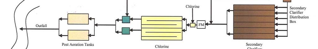
37 Cox Creek WRF Flow Diagram High Flow Management ENR Reactors Membrane Tanks Permeate To Disinfection Split RAS Primary Box Effluent Fine Screens RAS Slipstream to Bio-Actiflo Polymer Peak Flow > 30 mgd EQ Tanks 1-5 Peak Flow Bioreactor CG INJ MAT Return for Treatment FeCl 3 Settler Underflow MicroSand

38 High Flow Management Process Bio-Actiflo figure provided by Krueger
39 Benefits of High Flow Mgmt. Approach Reduces required membrane area by 33% Reduces membrane tank aeration requirements (number and size of blowers) Reduces membrane tank and building footprint by almost 40% Reduces the amount of energy required to maintain off-line membrane tanks in operation Reduces future membrane replacement costs Results in net reduction of both capital and O&M costs


40 MBR Final Design Criteria Caustic Methanol Ferric Primary Effluent Pre-Anoxic 1 Pre-Anoxic 2 Aerobic 1 Aerobic 2 Aerobic 3 Aerobic 4 Post Anoxic 1 Post-Anoxic 2 Membranes Permeate WAS DESIGN FLOW CONDITION FLOW RATE Rated Capacity, mgd (Nominal) 15.0 Average Daily Flow with recycles, mgd 15.7 Maximum Monthly Flow with recycles, mgd 19.4 Peak Hour Flow with recycles, mgd 30.0 GE/Zenon ZW500d Cassette Siemens/MemJet B30R Cassette Enviroquip/Kubota EW400
41 Pre-Selection Process Membrane Pre-Selection RFP Written to Encourage Open Competition Scope of Supply for Membrane Filtration Equipment supplier: Membranes and Membrane Units Permeate Pumps Membrane Cleaning Systems Piping and Valves Instrumentation and Controls Membrane Repair and Replacement Warranty RFP issued on April 16, 2009 Technical and Price Proposals received on July 9, 2009 Two firms submitted (GE/Zenon and Siemens) Evaluation based on 60% Cost, 40% Non-cost GE/Zenon selected as Membrane Supplier

42 Proposed Site Plan Copyright GHD 2009
43 Current Project Status January 2007: ENR Process selection completed April 2007: Schematic Design Report completed June 2010: Membrane Pre-Selection Process completed Project implementation includes three separate construction contracts: Phase 1: Primary Clarifiers and other Auxiliary Systems Phase 2: Fine Screens, ENR Reactors, Membrane Tanks and Related Improvements Phase 3: Non-ENR funded plant improvements (Headworks Improvements, Disinfection Upgrade, Odor Control,Thickener Improvements) Facility Start-up expected in 2015.
44 Project Schedule Phase 1 Construction Phase 2 Design Bid Construction Membrane Optimization Process Optimization Phase 3 Design Bid Construction
45 Questions?