DEVELOPMENTS IN IMPELLER TECHNOLOGY FOR MIXING VISCOUS, NON-NEWTONIAN FLUIDS. Richard K. Grenville Director of Mixing Technology
|
|
|
- Emery Reynolds
- 5 years ago
- Views:
Transcription

1 DEVELOPMENTS IN IMPELLER TECHNOLOGY FOR MIXING VISCOUS, NON-NEWTONIAN FLUIDS Richard K. Grenville Director of Mixing Technology ASC Convention Atlanta Marriott Marquis, Atlanta GA 5 th April 2017
2 TOPICS Introduction. Why mixing? Impeller characteristics: Flow versus Shear Efficiency Flow. Shear. New developments: Flow and Shear Examples.
3 External pressures: Market for expected to grow by 4.5 % world wide. Reduction in solvent use: Government and Consumer Different regulations across globe New uses / markets. Internal pressures: Product development to meet new markets Fit new formulations into existing plant facilities Increase production in existing facilities: Mix faster?! Batch to batch uniformity: Raw material costs Cost of rejected batches BUSINESS DRIVERS
4 Compare with other industries: Paint and coatings: Reduce VOCs Higher solids / pigments Batch uniformity Food feel is attribute: Tomato paste Chocolate Polymers: CRITICAL SUCCESS FACTORS Molecular weight and distribution Paper stock: Reduce water increase concentration All addressed by understanding the impact of fluid properties (viscosity) on mixing.
5 Smith (Trans IChemE., 1990): IMPORTANCE OF MIXING US chemical industry loses $ ($ 10 billion) each year due to poor mixing: 1 % increase in yield ~ $ One day of down time ~ $ Examples: Low yields in chemical reactions: Change in selectivity on scale-up By-products, MWD, etc Longer than expected batch / cycle times. Poor heat transfer / hot spots. Others..?
6 WHAT IS MIXING? (Etchells) Mixing is the application of mechanical motion in order to create Mean Flow fluid dynamic effects Shear which achieve a desired process result.

7 IMPELLERS FOR FLOW
8 Blend time: Time taken to reach C ± x % BLEND TIME c x = 100 c C Exponential approach to uniformity. Δc' = exp( kθ)

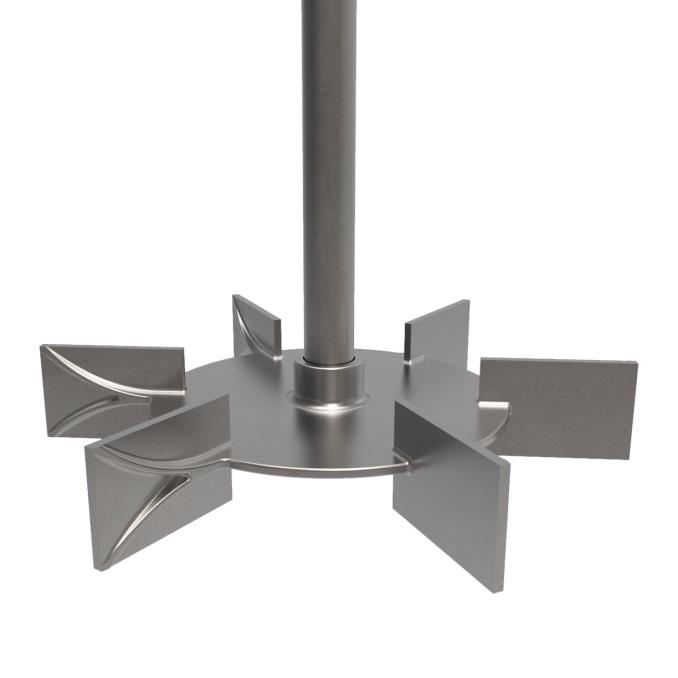
9 IMPELLERS FOR SHEAR

10 Brown (2010) and PMSL PUMPING EFFICIENCY
11 Objective method: BLEND TIME EXPERIMENTS Conductivity Measure in regions of differing mixing intensity Try and correlate results: Universal blend time correlation? Dimensionless blend time is product of impeller rotational speed and measured blend time: Nθ

12 TEST METHOD Experimental set-up: Three probes in regions of different mixing intensity: 1 - Under Impeller 2 - Between Shaft and Wall 3 - Behind Baffle Tracer added to liquid surface. Geometrically identical at all three scales.
13 RMS RESULTS - 4PBT (T/3 & T/2) D = T/3 D = T/2
14 CORRELATION D = T/3 D = T/2
15 TURBINE IMPELLERS - OPERATING REGIMES Turbulent Regime: Po = Constant Nθ = Constant Hoogendoorn, Private Communication, 1988 Transitional Regime: Po Constant Nθ Re -1 Laminar Regime: Po Re -1 Nθ Re -10
16 BLEND TIME Grenville et al. (MIXING XVIII, 2001) using Rieger s data: Nθ = Constant Nθ = KP Empirical correlation no physical basis. Concluded that high K P impeller is most efficient for blending: Lowest power input for desired blend time running costs Need bigger impeller (more steel) capital costs

17 OTHER DATA SOURCES
18 SHEAR Impellers that generate shear are required for size reduction: De-agglomeration and wetting of pigment added to liquid Reduction of droplet size in dispersion of immiscible liquids Rarely break down primary particles: Use Media or Sand Mills High energy High-pressure homogenizers for emulsions.

19 DROP SIZE vs. POWER PER MASS

20 HSD HSDs are inefficient pumps. But efficient dispersers. Poor flow can cause region near impeller to overheat. Ideally balance circulation with shear.

21 X-RAY STREAK PHOTOGRAPHY Impeller Blade Elson, Chem. Eng. Comm., 1990
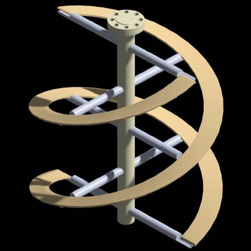
22 NEW DEVELOPMENT Need impeller that combines flow and shear generation capabilities. Alternative is double shaft system with HSD and Anchor / Ribbon combination: Still generate hot spots Two drives / motors Two sealing systems Use Bi-Directional impeller CounterFlow.
23 COUNTERFLOW
24 Brown (2010) and PMSL PUMPING EFFICIENCY
25 ATTRIBUTES Generally supplied with large impeller to tank diameter ratio: > 0.6 High shear zone where down and up-pumping blades meet: Large velocity gradient high shear rate Currently tested: Viscosity of 2 million cp Reynolds number < 0.1 Yield stress > 75 Pa


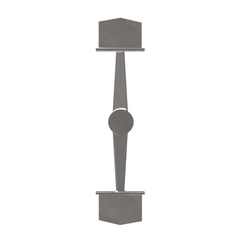
26 High solids slurry COMPARISON: TURBINE vs. CF


27 EXAMPLE COAL SLURRY Impeller diameter: Motor power: 320 inches 30 HP
28 CONCLUSIONS Impellers in stirred tanks are pumps: Machines that move fluid Need to decide if process requires: Efficient pumping Flow Inefficient pumping Dispersion Or combination of flow and shear Commonly used impellers provide one not both. CounterFlow impeller can provide both. PMSL lab can: Measure fluid rheology Perform mixing tests Scale-up fluid mechanics / physics meet chemistry.
29 29