Complex Sewage Disposal Course 2017
|
|
|
- Myrtle Morrison
- 5 years ago
- Views:
Transcription

1 Complex Sewage Disposal Course 2017

2 Updates to the Technical Guidance Manual This information is based on the most recent version of the TGM. Updates from previous versions can be found on DEQ s website
3 Complex Systems and Licensing Complex installers may install any sewage disposal system currently listed in the Technical Guidance Manual as well as experimental systems. Public works contractors may install any central or municipal system while under the supervision of professional engineer licensed in Idaho. IDAPA
4 Complex Systems Not Requiring an Engineer Extended treatment package systems In trench sand filter Pump to gravity pressure distribution Two cell infiltrative system Remediation components Proprietary waste water treatment systems* *Proprietary systems may or may not require engineering dependent on the system.
5 Complex Systems Requiring an Engineer At-grade soil absorption system Drip distribution system Evapotranspiration and evapotranspiration/infiltrative system Experimental systems Grey water systems, if they are pressurized Individual lagoon Intermittent sand filter Large soil absorption systems Pressure distribution systems Public systems* Recirculating gravel filter Sand mound Subsurface flow constructed wetland *Engineering is not required for public systems when the cost of construction, reconstruction, repairs and maintenance is less the $10,000.
6 Operation and maintenance Operation and maintenance of complex sewage disposal systems not designed by an engineer is generally found in the Technical Guidance Manual or in the design manual provided by the product manufacture. All systems designed by an engineer must submit an operations and maintenance manual with the application. TGM Some systems require operations and maintenance be performed by an O&M entity/service provider, with annual reporting.
7 IDAPA 58 - DEPARTMENT OF ENVIRONMENTAL QUALITY INDIVIDUAL/SUBSURFACE SEWAGE DISPOSAL RULES DOCKET NO NOTICE OF RULEMAKING - ADOPTION OF PENDING RULE EFFECTIVE DATE: This rule has been adopted by the Board of Environmental Quality (Board) and is now pending review by the 2017 Idaho State Legislature for final approval. The pending rule will become final and effective on July 1, 2017 unless prior to that date the rule is rejected in whole or in part by concurrent resolution in accordance with Sections and , Idaho Code. AUTHORITY: In compliance with Section , Idaho Code, notice is hereby given that the Board has adopted a pending rule. This action is authorized by Chapters 1 and 36, Title 39, Idaho Code. DESCRIPTIVE SUMMARY: A detailed summary of the reason for adopting the rule is set forth in the initial proposal published in the Idaho Administrative Bulletin, January 6, 2016, Vol. 16-1, pages 200 through 207. After consideration of public comments, the rule has been revised at Sections 006 and 009. The remainder of the rule has been adopted as initially proposed. The Rulemaking and Public Comment Summary can be obtained at or by contacting the undersigned. IDAHO CODE SECTION D STATEMENT: This rule regulates an activity not regulated by the federal government. Chapters 1 and 36, Title 39, Idaho Code, grant authority to the Board to adopt rules and standards to protect the environment and health of the state of Idaho for the installation of cottage site sewage treatment facilities and for the issuance of pollution source permits. FISCAL IMPACT STATEMENT: The following is a specific description, if applicable, of any negative fiscal impact on the state general fund greater than ten thousand dollars ($10,000) during the fiscal year when the pending rule will become effective: Not applicable. ASSISTANCE ON TECHNICAL QUESTIONS: For assistance on technical questions concerning this rulemaking, contact Tyler Fortunati at tyler.fortunati@deq.idaho.gov or (208)

8 Pumping Sewage Pump Total head pressure Is the pump designed for sewage Pump controller Time dose or demand dose Location 2-3 above pump


9 Dosing Chambers Location Floatation Filter In tank pumps Approved dosing chambers are listed in section 5.3 of the TGM TGM Section 4.19
10 More on Pumping Dose volume Pipe volume Drain-back Siphoning Table 4.19 Gallons Per Foot of Pipe Length Diameter (inches) Schedule Class Class Class

11 Installer Designed Complex Systems


12 Pump to Gravity Distribution A drop or distribution box must be used. Engineering may be required TGM Section 4.19
13 Two Cell Infiltrative System TGM Section 4.27
14 Two Cell Infiltrative System 100 feet from property line 300 feet from neighboring dwellings Parcel must be 5 or more acres Located with maximum exposure to wind and sun TGM Section 4.27
15 In-trench Sand Filter Used to excavate through unsuitable soils to suitable soils below 48. Drain field may be standard or alternative. Pretreatment may be used to reduce setback to groundwater. Medium sand must be used underneath drainfield to a maximum depth of 8. Anything deeper than 8 must use pit run to 8 of depth, then medium sand. TGM Section 4.23

16 In-trench Sand Filter Standard TGM Section


17 In Trench Sand Filter Enveloped Standard enveloped in trench sand filter For installation in unsuitably course soil Sized at 1.2 GPD/ft 2 Pretreated enveloped in trench sand filter Sized at 1.7 GPD/ft 2 TGM Section

18 In-trench Sand Filter Enveloped with pressure distribution May be used over any type of limiting layer This system must be engineered TGM Section
19 Extended Treatment Package Systems ETPS treat wastewater after the septic tank before disposal in a drainfield. Approved ETPS units are listed in section 5.4 of the TGM. Limiting Layer Vertical Separation Distance for All Soils Systems >2,500 gpd Impermeable Layer 2 Fractured Rock or Very Porous Layer Normal High Ground Water Seasonal High Ground Water Soil Design Sub Group Application Rate (gallons/square foot/day) A A-2a 1.2 A-2b 1.0 B B C C TGM Section 4.8

20 Extended Treatment Package Systems Systems require a contract with an approved operations and maintenance entity as well as monitoring and annual reporting TGM section 4.8
21 Remediation Components Must be permitted. Tank must be pumped and inspected. Installed in accordance with the manufactures directions. Risers and effluent filters are required. A distribution box, inspection port, or other means of measuring progress may be required. Approved remediation components are listed in section 5.12 of the TGM. If the component does not remediate the drainfield within 30 days the system is considered failing. TGM Section 4.30

22 Engineered Systems Questions so far? Who needs a short break?
23 A Note on Engineers The engineer must be licensed as a P.E. in Idaho Familiar with waste water The engineer is responsible for submitting an as-built at the completion of the project.

24 Pressure Distribution System Pressurized systems may be required as a part of alternative systems for pretreatment or disposal of effluent Required in drainfields with 1,500 or more square feet of actual trench bottom Minimum residual head is 5 feet TGM Section 4.19
25 Grey Water Systems When Pressurized All standard setbacks apply Grey water lines must be marked in accordance with the plumbing code The number of occupants is used to determine daily flow TGM Section 4.13
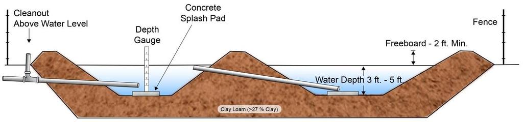
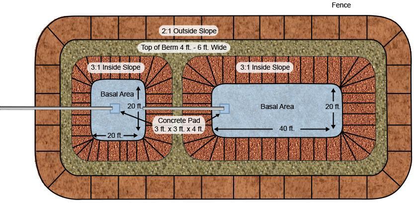
26 Individual Lagoon 200 setback to property line Site slope may not exceed 12% Not to be placed in areas that freeze for more than 3 months Or where precipitation is greater than evaporation 10 acre minimum lot size, variance required from 5 acre to 10 Lagoon area must be compacted Area must be fenced TGM Section 4.16

27 Evapotranspiration and Evapotranspiration/Infiltrative systems TGM Section 4.6
28 Evapotranspiration and Evapotranspiration/Infiltrative systems Seasonal ground water must not come within 6 of liner 100 setback to wells and surface water Site must not be subject to flooding High water alarm and standpipes are required Distribution laterals must be wrapped with geotextile fabric The ETI system are similar to ET just put in C type soils with no liner, or a clay based liner. TGM Section 4.6
29 Intermittent Sand Filter Reduce separation distances and drainfield size The sand container must meet the same separation distances as a septic tank, except, the bottom of the container may not be within 12 inches of seasonally high ground water Limiting Layer Vertical Separation Distance for All Soils Systems >2,500 gpd Impermeable Layer 2 Fractured Rock or Very Porous Layer Normal High Ground Water Seasonal High Ground Water Soil Design Sub Group Application Rate (gallons/square foot/day) A A-2a 1.2 A-2b 1.0 B B C C TGM Section 4.22

30 Intermittent Sand Filter TGM Section 4.22


31 Recirculating Gravel Filter Pea gravel TGM Section 4.21


32 Recirculating Gravel Filter Minimum recirculation ratio is 5:1 Maximum 7:1 Timed dosing is required Doses volume should be 10.4% of the daily flow volume Gravity flow splitter Pressurized splitter valve TGM Section 4.21
33 Drip Distribution System 2 minimum separation of drip tubes Final depth of 1 minimum 2 set back to impermeable layers 1 to all other limiting layers 100 micron or smaller filter Vacuum relief valves required TGM Section 4.5
34 Large Soil Absorption System 2,500 gallons or more per day Maximum disposal unit flow is 10,000 GPD At least two disposal systems designed to accept the daily flow will be constructed with an area for one more reserved Design engineer will create and O&M manual Monitoring is required, with an annual report to be filed by January 31 each year IDAPA
35 Large Soil Absorption System TABLE -- SEPARATION DISTANCES Feature of Interest Design Soil Group A B C All Domestic Water Supplies Sewage Volume - 2,500-5,000 GPD TABLE -- EFFECTIVE SOIL DEPTHS Site Conditions Design Soil Group Limiting Layer A B C Impermeable Layer Fractured Bedrock, Fissured Bedrock or Extremely Permeable Material Normal High Groundwater Level Seasonal High Groundwater Level Sewage Volume - 5,000-10,000 GPD Property Lines Sewage Volume - 2,500-5,000 GPD Sewage Volume - 5,000-10,000 GPD Building Foundations - Basements Sewage Volume - 2,500-5,000 GPD Sewage Volume - 5,000-10,000 GPD Downslope Cut or Scarp Impermeable Layer - Below Base Separation Distance - Between Modules IDAPA

36 At Grade Soil Absorption System Must be pressurized Designed at 1.5 time the wastewater flow 500 gallons per day maximum flow, excluding safety factor Drain rock must be used Design Group A B C-1 C-2 Maximum Slope (%) TGM Section 4.2


37 Sand Mound Systems Pressurized distribution is required Designed at 1.5 times the daily flow Setback reductions depend on the depth of sand beneath the bed Maximum slopes of 20% for A and B soils 12% for C-1 and 6% for C-2 Sludge in septic tank should be checked annually and pumped at 40% TGM Section 4.24

38 Sand Mound Systems Cells should be as long and narrow as possible Vegetation must be removed and the entire area scarified then plowed 6 to 8 inches deep before sand is placed. TGM Section 4.24


39 Subsurface Flow Constructed Wetlands TGM Section 4.27
 at inlet and outlet, pea gravel (1 -.75 ) between Peat, or similar material, for the planting media TGM Section 4.")
40 Subsurface Flow Constructed Wetlands Concrete or 30 mil PVC/equivalent container 12 berm around cell Drain rock ( ) at inlet and outlet, pea gravel ( ) between Peat, or similar material, for the planting media TGM Section 4.27
41 Experimental Systems Site must be suitable for a standard or alternative system A variance is required Operations and Maintenance Manual must be provided with the application. This manual must be approved before a permit will be issued. Approval is at the discretion of DEQ TGM Section 4.7
42 Proprietary waste water treatment systems TGM section 5.14
43 Alternative System At-Grade Soil Capping Fill Absorption System (4.3) System (4.2) Drip Distribution System (4.5) Experimental System (4.7) Extended Treatment Package System (4.8) Extra Drainrock Trench (4.9) Gravel-less Trench System (4.11) Pressure Recirculating Distribution Gravel Filter System (4.19)(4.21) Intermittent Sand Filter (4.22) In-Trench Sand Filter (4.23) Sand Mound (4.24) Seepage Pit/Bed (4.25) Drainfield Steep Slope Remediation System (4.26) Components (4.29) At-Grade Soil Absorption S N A* A A N N A* A A N N N N A System (4.2) Capping Fill System (4.3) N S A A A A A A A A A N N N A Drip Distribution System (4.5) A* A S A A A* A* A A** A** A* A* N A* A Experimental System (4.7) A A A S A A A A A A A A A A A Extended Treatment Package System (4.8) Extra Drainrock Trench (4.9) A A A A S A A A A A A A A A A N A A* A A S N A A A A N N A A Gravelless Trench N A A* A A N S A A* A* A A N A A System (4.11) Pressure Distribution A* A A A A A A S A A A A N A A System (4.19) Recirculating Gravel Filter (4.21) Intermittent Sand Filter (4.22) In-Trench Sand Filter (4.23) Sand Mound (4.24) Seepage Pit/Bed (4.25) A A A** A A A A* A S A A A A A A A A A** A A A A* A A S A A A A A N A A* A A A A A A A S N N A A N N A* A A N A A A A N S N N A N N N A A N N N A A N N S N A Steep Slope System (4.26) N N A* A A A A A A A A N N S A Drainfield Remediation A Components A A A A A A A A A A A A A S (4.29) TGM Section Notes: A Compatible alternative system types; N Not compatible alternative system types; S Same alternative system type; (*) May be used as the distribution method within the drainfield; (**) May be used as distribution method within the filter as well as the drainfield.

44 Questions Free Answer 18) D