Monitoring Well Installation Report
|
|
|
- Thomas Freeman
- 5 years ago
- Views:
Transcription

1 Monitoring Well Installation Report Comanche Station Xcel Energy August 1, 2016 Updated June 14, 2018 Comanche Station, Pueblo County, Colorado
2 Xcel Energy Monitoring Well Installation Report Comanche Station Table of Contents 1.0 Introduction Background Information Field and Laboratory Methods Borehole Drilling Soil Samples - Geotechnical Analysis Well Construction Well Development Well Survey Groundwater Level Measurement and Aquifer (Slug) Testing Decontamination of Field Equipment Field and Laboratory Results Borehole Drilling Soil Samples Geotechnical Analysis Well Construction Well Development Well Survey Groundwater Level Measurement and Aquifer (Slug) Testing References List of Tables Table 1. Summary of Geotechnical Testing Results at Comanche Station, Table 2. Well Construction Details for Groundwater Monitoring Wells W-4, W-5, W-6, MW-5, MW-6 at Comanche Station, List of Figures Figure 1. Vicinity Map for Comanche Station... 3 Figure 2. Well Location Map, Comanche Station... 4 i
3 Xcel Energy Monitoring Well Installation Report Comanche Station List of Appendices A. Borehole Logs B. Geotechnical Soil Testing Results and Chain of Custody Records C. Well Construction Diagrams D. State Well Permits ii
4 Xcel Energy Monitoring Well Installation Report Comanche Station Table of Abbreviations and Acronyms Abbreviation AMSL bgs BTOC CCR cm/sec HP Geotech µs/cm NTU PSCo SSD TOC USCS Definition above mean sea level below ground surface below top of casing Coal Combustion Residuals centimeter per second Hepworth-Pawlak Geotechnical, Inc. microsiemens per centimeter nephelometric turbidity unit Public Service Company of Colorado Site Services Drilling, LLC top of casing Unified Soil Classification System iii
5 Xcel Energy Monitoring Well Installation Report Comanche Station 1.0 Introduction The purpose of this Monitoring Well Installation Report is to document details pertaining to the drilling, construction, and development of two groundwater monitoring wells installed in 2017 and three monitoring wells installed in 2015 at the Xcel Energy Comanche Generating Station (Comanche Station) in Pueblo, Colorado (Figure 1). The groundwater monitoring system is intended to support compliance with the U.S. Environmental Protection Agency s final Coal Combustion Residuals (CCR) Rule (40 CFR Parts 257 and 261). Comanche Station has two units 1, an impoundment and a landfill, subject to the CCR Rule. The drilling and well installation was performed in accordance with the State of Colorado Water Well Construction Rules (2 Code of Colorado Regulations 402-2). HDR was contracted to locate, permit, and oversee the installation of the three groundwater monitoring wells at Comanche Station. HDR retained Hepworth-Pawlak Geotechnical, Inc. (HP Geotech) in 2015 and Site Services Drilling, LLC (SSD) in 2017 to provide on-site drilling services, while HDR provided field monitoring of the drilling, well installation, and development. All on-site personnel completed the site-specific safety training. Additionally, daily safety briefs were conducted by the on-site project team prior to commencing work. The training and safety briefs were documented in accordance with the PSCo CCR Rule Compliance Health & Safety Plan. 2.0 Background Information Prior hydrogeologic and geotechnical investigations conducted at Comanche Station are identified and summarized in the Comanche Station Monitoring Well Installation Plan (HDR, 2015a). Comanche Station is underlain by unconsolidated colluvium consisting of stiff clays and silts, with interbedded sand and gravel west and northwest of the CCR landfill. Typical colluvium thickness is less than 20 feet but ranges between 5 and 75 feet (Woodward-Clyde, 1987; URS, 2005). The Pierre Shale is the uppermost bedrock at the Comanche Station and has a measured hydraulic conductivity of 3 x to 3 x 10⁻⁷ cm/sec. The uppermost aquifer beneath the Site is the Dakota Sandstone at a depth of over 1,400 feet (GeoTrans, Inc., 2009). Approximately 1,400 feet of lowpermeability shale deposits separate the surface impoundments from this aquifer. Tetra Tech (2015) estimated that the groundwater velocity through the Pierre Shale is 0.1 feet per year. Given that the Pierre Shale is estimated to be over 230 feet thick beneath the Site, it will take 2,300 years just to migrate through the Pierre Shale. It will take an additional 12,200 years to migrate through the underlying shale deposits before leachate from the ADF would reach the Dakota Sandstone Aquifer. The shallow unconsolidated colluvium deposits beneath the site have been predominantly unsaturated, with some isolated areas of perched water 2 (GeoTrans, Inc., 2009). Areas of perched water are likely controlled by the bedrock topography where water becomes trapped by topographic lows in the shale bedrock surface (GeoTrans, Inc., 2009). The conceptual model for surface water infiltration is that it migrates vertically into low-permeability bedrock and/or is trapped in topographic 1 Comanche Station includes three coal-fired generation units. All CCR generated at Comanche Station is stored in two active CCR units subject to compliance with the CCR Rule: a CCR impoundment and a CCR landfill (Figure 2). The CCR impoundment is located southeast of the coal storage area, and the CCR landfill is west of the raw water storage pond. 2 Only two of the seven previously installed wells at the site, MW-3 and W-3, have contained measurable water, and most borings previously drilled at the site, including boreholes that penetrate the Pierre Shale, have been dry.
6 Xcel Energy Monitoring Well Installation Report Comanche Station lows in the bedrock surface prior to migrating vertically (GeoTrans, Inc., 2009). A potential southsoutheasterly flow gradient is assumed based on the ground surface topography, which slopes to the south-southeast towards the St. Charles River. The alluvial aquifers associated with the Arkansas River (north), the St. Charles River (south), and Salt Creek (west) do not extend beneath the site (Xcel Energy, 2005). Given the lack of a laterally extensive shallow groundwater system in the colluvium deposits beneath the site and the depth of the uppermost aquifer (Dakota Sandstone), a wet/dry monitoring well system has been selected to detect changes in perched groundwater conditions and/or potential contaminants from the ash landfill and CCR impoundment. The five new monitoring wells installed at Comanche Station (W-4, W-5, W-6, MW-5, and MW-6) were sited based on monitoring requirements in the CCR Rule, facility design, and existing hydrogeologic data for the vicinity, as described in the Groundwater Monitoring System Certification (HDR, 2018). MW-5 and MW-6 were installed in 2017 to provide coverage for the lateral expansion of the landfill. Well locations are shown on Figure 2.

7 Xcel Energy Monitoring Well Installation Report Comanche Station Figure 1. Vicinity Map for Comanche Station

8 Xcel Energy Monitoring Well Installation Report Comanche Station Figure 2. Well Location Map, Comanche Station
9 Xcel Energy Monitoring Well Installation Report Comanche Station 3.0 Field and Laboratory Methods 3.1 Borehole Drilling The boreholes for wells W-4, W-5, and W-6 were drilled by HP Geotech using a hollow stem auger drilling method from November 9 through 11, The boreholes for MW-5 and MW-6 were drilled by Site Services Drilling (SSD) using the same method from August 7 through 8, Utility locations were identified prior to beginning drilling operations. However, to verify the absence of any buried utilities, the driller advanced soil borings from the ground surface by using a pot-holing technique to a minimum depth of 8 feet prior to drilling. The borehole was then advanced using the hollow stem auger drilling method with a CME-55 drill rig. The nominal borehole diameter was 8 inches in 2015 and 6 inches in 2017 to accommodate construction of 2-inch diameter wells. Screen depth was targeted for the top of a perched water-bearing zone, if encountered, or 5 feet above the top of weathered shale/claystone bedrock in order to intersect the colluvium-bedrock contact. Boreholes were drilled to a minimum of 15 feet beneath the top of the weathered shale/claystone at the site or until the borehole could not be further advanced. This resulted in total borehole depths that ranged from 25 feet to 42 feet, as further described in Section 4.3. An HDR geologist was present during drilling operations to collect samples and log the subsurface material, in addition to overseeing site safety and proper well construction. Soil samples from boreholes were collected in plastic bags and logged every 5 feet by the field geologist during drilling to document lithologic soil characteristics. The geologist visually classified soil type, consistency/relative density, color, and water content in accordance with the Unified Soil Classification System (USCS) as well as grain size, mineralogy, sorting, rounding, hardness, and matrix/clast support, among other textural properties. Samples were placed in sample bags labeled with the borehole identification and depth interval. One undisturbed soil sample from each well was collected within the well screen depth interval and submitted to a lab for hydraulic properties analysis, as described in Section 3.2. Soil samples were not collected in Boring logs for each borehole are provided in Appendix A. Soil cuttings, fluids, and potholing slurry generated during drilling were transported to and disposed of at the existing onsite ash landfill. Drilling equipment was decontaminated with potable water before moving to the next borehole. 3.2 Soil Samples - Geotechnical Analysis Soils were logged from the cutting returns during drilling wells W-4, W-5, and W-6 and classified based on the USCS. During drilling, one undisturbed soil sample was obtained from each borehole at a depth coinciding with the well screen depth. An 18-inch long California Modified Style Split- Spoon Sampler was used to collect the undisturbed core of sediment. The undisturbed soil samples (one from each well) were submitted to HP Geotech for analysis of the following parameters: Grain-size: Sieve and Hydrometer (ASTM D421/422) Total Porosity (SW9) Bulk Density (ASTM D2937) Moisture Content (ASTM D2216)
10 Xcel Energy Monitoring Well Installation Report Comanche Station Specific Gravity (ASTM D854) Analysis was completed in accordance with the method for grain-size analysis using sieve and hydrometer described in ASTM D421/422 (ASTM D421-85, 1998 and ASTM D422-63, 2007). Chain of custody documentation and laboratory results are provided in Appendix B. Samples were not collected from MW-5 or MW-6 boreholes. 3.3 Well Construction Once the target drilling depth was reached at each location, the 2-inch diameter, Schedule 40 PVC casing and well screen (0.010-inch slots) were assembled and lowered into the borehole. Approximately 10 feet of screen was installed in each new well. The top of the well screen was placed at the top of a perched water-bearing zone, where encountered. Where perched water was not encountered, the well screen was immediately above the top of weathered shale/claystone bedrock to intersect the colluvium-bedrock contact. To capture infiltrating perched water 3, a 10-foot long sump consisting of blank casing was placed beneath the screen, as requested by CDPHE in a meeting with Xcel Energy on April 24, 2014 (Tetra Tech, 2014). However, a 5-foot long sump was placed beneath the well screen of MW-6 due to drilling refusal. After PVC casing and screen placement in the borehole, sand filter pack and the bentonite seal was placed via gravity feed from the surface into the annular space. T he sump was sealed in with bentonite to 2-feet below the bottom of the screen. The filter pack consisted of (sieve size) washed silica sand emplaced from approximately 2 feet below the bottom of the screen to approximately 0.5 to 2 feet above the well screen. The annular seal of medium bentonite chips was placed above the top of the filter pack and hydrated in lifts throughout placement, while the remaining drill casing was removed from the borehole using the hydraulic jacks. An annular surface seal consisting of neat cement was installed from the top of the bentonite to the surface. All wells were finished with a 2-foot-by-2-foot concrete pad using Quickrete fast setting concrete, extending to a depth of approximately 0.5 to 2 feet below grade (to the top of the bentonite grout). Each well included a PVC stick-up. Two bollards were placed on either side of monitoring wells W-4 and W-5, parallel to the road; three bollards were installed around monitoring wells MW-5, MW-6, and W-6. Each well was secured with a protective steel casing and lock. Well construction is further described in Section Well Development Wells are typically developed over several days to improve hydraulic connectivity in the area immediately surrounding the well and remove any fluids introduced during drilling. Well development involves removing as much of the introduced drilling fluids, cuttings, and particulates from within and adjacent to the well as possible. Development did not begin until at least 12 hours after the wells had been grouted to ensure grout had sufficiently set. Wells were to be developed by surge blocking and pumping. This method involves moving a surge block up and down the well screen and casing, which alternately forces water in and out of the 3 Previously constructed wells W-1, W-2, and W-3 incorporated a 2-foot sump to capture infiltrating perched water. Due to the lack of a laterally extensive shallow groundwater system in the colluvium deposits beneath the site and the depth of the uppermost aquifer (Dakota Sandstone), a wet/dry monitoring well system is an effective way to detect changes in perched groundwater conditions and/or potential contaminants from the ash landfill and CCR impoundment.
11 Xcel Energy Monitoring Well Installation Report Comanche Station screen, loosens sediment, and draws fine-grained materials into the well, then removing the purge water and fine sediment from the well using a pump. Wells W-5 and MW-5 were found to be dry; therefore, well development was not attempted. Well development at W-4, W-6 and MW-6 is further discussed in Section Well Survey Surveying of the monitoring wells was performed by professional surveyor Edward-James Surveying, Inc. after well completion. The surveyor recorded elevations of the top of PVC casing (point at notch on the north side of the casing top) and ground surface using a level loop. The northing and easting coordinates of the wells were initially surveyed using a local coordinate system and converted to NAD 1983 UTM Zone 13 South. 3.6 Groundwater Level Measurement and Aquifer (Slug) Testing Slug tests are typically performed on new monitoring wells to obtain estimates of hydraulic conductivity for shallow unconfined aquifers. Slug testing consists of injecting and removing a volume of water and recording the change in groundwater level over time, then calculating aquifer parameters based on the groundwater level response. Slug testing was not performed at the new Comanche Station wells because the well screens were not installed at the bottom of the well. Each well has a sump and the static water level is towards the bottom of the screen at approximately the screen/sump boundary. Therefore, dropping a slug into the water in the sump would not result in a response by the shallow groundwater geologic formation outside the well. 3.7 Decontamination of Field Equipment Field instrumentation (such as interface probes or water quality meters) was decontaminated between sample locations by rinsing with an Alconox/distilled water solution followed by a potable water rinse and a final rinse with deionized water. 4.0 Field and Laboratory Results 4.1 Borehole Drilling Boring logs for each borehole are provided in Appendix A. Soil cuttings from the borehole samples consisted primarily of silt and clay, with some sand. Iron staining was noted in samples collected from all three borings surrounding the impoundment. Shale was encountered at approximately 14 feet bgs in W-4, W-5, and W-6; silt with shale deposits was logged at W-6 while clay with shale was recorded at wells W-4 and W-5 at this depth. This was presumed to be the top of the Pierre Shale formation. Silt was encountered below the shale layers at all three borings drilled surrounding the impoundment. Soil cuttings ranged from dry to moist. A perched, water bearing zone was encountered at wells W-4 and W-6; W-5 was dry. Approximately 24 hours after drilling, depth to perched water was measured at feet bgs at W-4 and feet bgs at W-6. Shale, presumed to be the top of the Pierre Shale formation, was encountered at approximately 24 feet below ground surface at MW-5 and approximately 35 feet at MW-6. Coarse gravel with sand and a 4-inch layer of brown clay was encountered at this depth at MW-6. Soil cuttings were dry in MW-5. Soil cuttings were dry in MW-6 until moisture was encountered beginning at 20 feet below the surface. Approximately 21 hours after drilling, depth to water was measured at 28 feet in MW-6 and MW-5 was dry.
12 Xcel Energy Monitoring Well Installation Report Comanche Station 4.2 Soil Samples Geotechnical Analysis The undisturbed soil samples collected from the well screen depth intervals of W-4, W-5, and W-6 analyzed for grain size and porosity by HP Geotech are summarized in Table 1. The soils laboratory results are presented in Appendix B. Table 1. Summary of Geotechnical Testing Results at Comanche Station, 2015 Well I.D. Sample Depth (feet bgs) Gradation Gravel (%) Sand (%) Silt and Clay (%) Porosity (%) Moisture Content (%) W W W Note: BGS = below ground surface Laboratory results show the wells are screened in silt and clay with some sand, with porosities between 35 and 40 percent, which is consistent with the silt and clay material noted in the drilling logs. A general range of hydraulic conductivity for such sediments is 10-9 to 10-4 centimeter per second (cm/s) (Fetter, 1994). 4.3 Well Construction A diagram for each well that documents well construction is provided in Appendix C. Approximately 10 feet of screen was installed in each well. The screen was placed above the Pierre Shale formation from approximately 3.4 to 13.4 feet bgs at W-4, 3.5 to 13.5 feet bgs at W-5, 5 to 15 feet bgs at W-6, 16 to 26 feet bgs at MW-5, and 27 to 37 feet bgs at MW-6. The 10-foot blank casing sumps were placed below each well screen; except at MW-6 a 5-foot blank casing sump was placed below the well screen. Total well depths (including the sumps) ranged from 23.4 to 42 feet bgs. Well construction details for all six wells are summarized in Table 2. State-issued well construction permits are included in Appendix D.
13 Xcel Energy Monitoring Well Installation Report Comanche Station Table 2. Well Construction Details for Groundwater Monitoring Wells W-4, W-5, W-6, MW-5, MW-6 at Comanche Station, Well ID Easting (State Plane, NAD 1983 UTM Zone 13 S meters) Northing (State Plane, NAD 1983 UTM Zone 13 S meters) Elevation TOC (feet AMSL) Well Total Depth (feet bgs) Depth of Screen Interval (feet bgs) Well Stickup (feet) W W W MW MW Notes: TOC = top of casing BTOC = below top of casing BGS = below ground surface Casing Type 2-inch PVC 2-inch PVC 2-inch PVC 2-inch PVC 2-inch PVC Depth to Water (feet BTOC) Static Water Level (feet AMSL)
14 Xcel Energy Monitoring Well Installation Report Comanche Station 4.4 Well Development On November 11, 2015, the depth to water was measured in wells surrounding the impoundment in preparation to begin well development. Well W-5 was found to be dry; therefore, well development was not attempted in this monitor well. Well development was not attempted at well W-4 due to the lack of water in the screened interval. Well development was attempted at well W-6 but was ultimately unsuccessful due to extremely slow recharge in the well, combined with a water level of only 3 feet within the wetted screened interval (above the sump). On August 8, 2017, the depth to water was measured at MW-6 in preparation to begin well development. Well development continued on August 9 and 10; approximately 315 total gallons of water was purged during the development of MW-6. Well development was not attempted at MW-5 due to the lack of water in the screened interval. 4.5 Well Survey Survey coordinates and elevations are provided in Table Groundwater Level Measurement and Aquifer (Slug) Testing Slug testing was not performed at the new Comanche Station wells because the well screens were not installed at the bottom of the well. Each well has a sump and the static water level is towards the bottom of the screen at approximately the screen/sump boundary. Therefore, dropping a slug into the water in the sump would not result in a response by the shallow groundwater geologic formation outside the well. Static water level measurements are provided in Table 2.
15 Xcel Energy Monitoring Well Installation Report Comanche Station 5.0 References Bouwer, H. and R.C. Rice, A slug test method for determining hydraulic conductivity of unconfined aquifers with completely or partially penetrating wells, Water Resources Research, vol. 12, no. 3, pp Dagan, G., A note on packer, slug, and recovery tests in unconfined aquifers, Water Resources Research, vol. 14, no. 5. pp Freeze, R.A. and J.A. Cherry, Groundwater, Prentice-Hall, Inc., Englewood Cliffs, NJ. GeoTrans, Inc. (2009). Surface Water Impoundment Infiltration Characterization Analysis, Public Service Company of Colorado, Comanche Station, Pueblo, Colorado, December 1, HDR, 2015a. Monitoring Well Installation Plan for Compliance with the Coal Combustion Residuals (CCR) Rule, Comanche Station. Xcel Energy. HDR, Groundwater Monitoring System Certification for Compliance with the Coal Combustion Residuals (CCR) Rule, Comanche Station. Xcel Energy. Tetra Tech, Inventory and Preliminary Classification Report, Waste Impoundments, Comanche Station, Pueblo, Colorado, November 1, Tetra Tech, Sitewide Monitoring Plan, Ash Disposal Facility, Comanche Station, Pueblo, Colorado, August 29, Tetra Tech, Engineering Design and Operations Plan, Ash Disposal Facility, Comanche Station, Pueblo, Colorado, January 13, URS, Geotechnical Investigation, Unit 3, Comanche Station, Pueblo, Colorado, March 2, Woodward-Clyde Consultants, Feasibility Investigation, Two Ash Disposal Areas for Comanche Power Station, Pueblo, Colorado. March Xcel Energy, Comanche Station Coal Ash Disposal Facility Design and Operations Plan. August 24, 2005.
16 Xcel Energy Monitoring Well Installation Report Comanche Station Appendix A Borehole Logs
17 Boring Log Page 1 of 1 Project Name Project No. Drilling Company Xcel CCR Boring No. W-4 Sample No. 1' below groung surface (bgs) Blow Count Location Comanche Power Depth (feet) HP Geotech Drilling Rig Type and Drilling Method Description (USCS) CME-55 Hollow Stem Auger (8-inch borehole) Remarks N/A 7.5YR 3/2; Sandy Silt (ML ), some gravel; nonplastic; noncohesive; dry Potholed to 8' on 11/9/2015 5' bgs N/A 10YR 5/3; Lean Clay (CL); stiff, med-high plasticity; cohesive; moist 5 W-4: 9' bgs 6-8 (Cal) 10' bgs (SS) 10 10YR 4/3; Lean Clay (CL); stiff, low plasticity; cohesive; some lamination; moist Fe staining. Cal sample at 9'bgs submitted for geotech analysis 10YR 4/3; Lean Clay (CL); very stiff, low plasticity; cohesive; laminated; moist 14' bgs (SS) 15 Alluvium/bedrock contact at 14'bgs Dark gray Gley 1 4/N; Lean Clay (CL) Black Shale, weathered; laminated Fe staining Fe staining 19' bgs (SS) As above Fe staining; hard, very micaceous 20 24' bgs (SS) Very dark gray Gley 1 3/N; Silt (ML); hard, non-plastic; non-cohesive; laminted; Fe staining; micaceous 25 dry to moist Logged By: Drilled/Sampled By: Total Depth (feet) Water Level (feet) Nick Hanrahan Brent McDaniel After Drilling: Hours After: Date Started: Date Completed: /10/ /10/2015
18 Boring Log Page 1 of 1 Project Name Project No. Drilling Company Xcel CCR Boring No. W-5 Sample No. 2' bgs Blow Count N/A Location Comanche Power Depth (feet) HP Geotech Drilling Rig Type and Drilling Method Description (USCS) CME-55 Hollow Stem Auger (8-inch borehole) 10YR 4/3; Fat Clay (CH) with Sand and some Gravel; high plasticity; cohesive; moist to wet (likely due to potholing) Remarks Potholed to 8' on 11/9/ ' bgs N/A As above W-5: 9' bgs 5-7 (Cal) 10' bgs (SS) 10 Brown 10YR 4/3; Lean Clay (CL), some gravel; stiff; medium plasticity; cohesive; dry to moist Cal sample at 9' bgs submitted for geotech analysis 14' bgs (Cal) As above. Hit a layer of shale bedrock with quartz vein, became laminated to Fe staining; quartz vein visible 15 15' bgs (SS) thinly bedded; hard 19' bgs (SS) As above; laminated Fe staining; gravel-size mic grains 20 24' bgs (SS) 25 Brown 7.5YR 4/4; fine-medium Sandy Silt (ML); some coarse; very stiff; nonplastic; non-cohesive; moist Logged By: Total Depth (feet) Water Level (feet) Nick Hanrahan After Drilling: Hours After: Date Started: 25 Dry 24 11/9/2015 Drilled/Sampled By: Brent McDaniel Date Completed: 11/9/2015
19 Boring Log Page 1 of 1 Project Name Project No. Drilling Company Xcel CCR Boring No. W-6 Sample No. 1' below ground surface (bgs) Blow Count N/A Location Comanche Power Depth (feet) HP Geotech Drilling Rig Type and Drilling Method Description (USCS) CME-55 Hollow Stem Auger (8-inch borehole diameter) 10YR 3/2; Silty Sand (SM) with Gravel; nonplastic; non-cohesive (Fill); moist Remarks Potholed to 8' on 11/9/ ' bgs N/A 10YR 3/2; Silt w/ Sand (ML); nonplastic, noncohesive; wet W-6: 9' bgs 10.5' bgs 8-11 (Cal) (SS) 10 Olive brown 2.5Y 4/3; Lean Clay (CL); very stiff; medium to high plasticity; cohesive; moist to wet Fe staining. Cal sample at 9' bgs submitted for geotech analysis 14' bgs (SS) 15 Top 14": As above; stiff Bottom 6": Gray Gley 1 5/N; Silt (ML) with Shale; stiff; nonplastic; cohesive; moist Fe staining. Alluvium; top of refusal 19' bgs (SS) Olive brown 2.5Y 4/3; Lean Clay (CL); stiff; medium plasticity, cohesive; moist Fe staining; micaceous 20 24' bgs (Cal) Dark grayish brown 10YR 4/2; Silt (ML); nonplastic; slightly cohesive, Very micaceous 25 laminated (shale); moist 29' bgs 50/5" (SS) As above; noncohesive Very micaceous 30 Logged By: Total Depth (feet) Water Level (feet) Nick Hanrahan After Drilling: Hours After: Date Started: /10/2015 Drilled/Sampled By: Brent McDaniel Date Completed: 11/10/2015
20 Boring Log Page 1 of 1 Project Name Project No. Drilling Company Xcel CCR Site Services Drilling, LLC Boring No. Location Drilling Rig Type and Drilling Method MW-5 Comanche Station CME-55 Hollow Stem Auger (6-inch diameter) Sample No. Blow Count Depth (feet) (0-8') Dry SILT 2.5Y 5/2 Description (USCS) Elevation (feet) Remarks Potholed to 8 ft 5 (8-9') Poorly graded fine SAND, very dry 5 YR 4/2 10 (9-14') Compacted SILT with white calcite laminates, very dry, stiff 7.5YR 6/3 4' of recovery from 8-14' core 15 (14-22') Compacted SILT with trace white calcite laminates, very dry, stiff 7.5YR 5/4 20 (22-24') Compacted SILT with increased calcite content and trace dark gray SILT laminae 7.5 YR 3/2 25 (24-29') Highly weathered SHALE bedrock 2.5Y 3/2 30 (29-36') Weathered SHALE bedrock Well Construction: Screen 16-26' Sump 26-36' 35 Logged/Sampled By: Drilled By: Total Depth (feet) Water Level (feet) M. Violette Site Services Drilling, LLC After Drilling: Hours After: Date Started: Date Completed: 36-8/8/2017 8/8/2017
21 Boring Log Page 1 of 1 Project Name Project No. Drilling Company Xcel CCR Site Services Drilling, LLC Boring No. Location Drilling Rig Type and Drilling Method MW-6 Comanche Station CME-55 Hollow Stem Auger (6-inch diameter) Sample No. Blow Count Depth (feet) (0-8') Dry SILT 2.5Y 5/2 Description (USCS) Elevation (feet) Remarks Potholed to 8 ft 5 (8-9') SAND with brittle SILT with white CLAY pieces 2.5Y 6/4 10 (9-12') SILT with SAND, brittle, very dry 7.5YR 5/4 15 (12-14') Well graded coarse SAND with GRAVEL, very dry, hematite and quartz present 5YR 5/6 (14-19') Coarse SAND with GRAVEL, large cobbles up to 3-inches in length, hematite and quartz present, very dry 5YR 5/6 2' of recovery from 14-19' core 20 (19-23') Coarse SAND with GRAVEL, large cobbles up to 2-inches in length, moist 2.5YR 5/4 2.5' of recovery from 19-24' core 25 (23-24') Same as above, 7.5YR 7/1 (24-29') Coarse GRAVEL with SAND. A 4-inch layer of brown CLAY at 27', some black SHALE pieces and cobbles up to 1-inch in length, micaceous 7.5R 5/4 2.5' of recovery from 24-29' core ( ') SILT with GRAVEL, medium to coarse SAND present, moist 7.5YR 6/4 ( ') Medium SAND with SILT 7.5YR 5/6 ( ') CLAY with SILT 7.5YR 5/4 (33-34') Medium to coarse SAND, moist to wet 7.5YR 5/4 (34-35') CLAY with some SILT, firm, dry 7.5YR 5/3 (35-42') Highly weathered SHALE bedrock, trace SILT 10YR 4/2 Well Construction: Screen 27-37' Sump 37-42' Logged/Sampled By: Drilled By: Total Depth (feet) Water Level (feet) M. Violette Site Services Drilling, LLC After Drilling: Hours After: Date Started: Date Completed: 42 28' 21 8/7/2017 8/7/2017
22 Xcel Energy Monitoring Well Installation Report Comanche Station Appendix B Geotechnical Soil Testing Results and Chain of Custody Records
23 Hepworth-Pawlak Geotechnical, Inc South Progress Way Parker, Colorado Phone: Fax: December 14, 2015 Anna Lundin HDR 1670 Broadway, Suite 3400 Denver, CO B Subject: Laboratory Tests Results Xcel Coal Combustion Residuals Rule Compliance Project, Comanche Power Station. Dear Ms. Lundin: This letter presents the results of laboratory tests performed on samples submitted for the subject project. The test results are presented on the attached Figures 1-3 and Table 1. If there are any questions, please feel free to contact us. Sincerely, HEPWORTH-PAWLAK GEOTECHNICAL, Inc. Cuong Vu, Ph.D., P.E. Reviewed by: Arben Kalaveshi, P.E B (Comanche) xmittal.doc
24 PERCENT PASSING HYDROMETER ANALYSIS SIEVE ANALYSIS TIME READINGS U.S. STANDARD SIEVES CLEAR SQUARE OPENINGS 435MIN. 60MIN. 19MIN. 4MIN. 1MIN. #200 # #50 #30 #16 #8 #4 3/4" 1 1/2" 3" 5" 8" CLAY(plastic) TO SILT(non-plastic) DIAMETER OF PARTICLE IN MILLIMETERS SAND GRAVEL FINE MEDIUM COARSE FINE COARSE COBBLES GRAVEL: 0% SAND: 14% SILT / CLAY: 86% BORING : MW4 Specific Gravity: 2.87 DEPTH : 9 feet Porosity : 36.2% Sieve Size / Particle Diameter (1") (3/4") (1/2") (3/8") (#4) (#10) (#16) (#30) (#50) (#) (#200) Percent Passing B HEPWORTH-PAWLAK GEOTECHNICAL, INC. HDR COMANCHE HYDROMETER AND SIEVE ANALYSIS FIG. 1
25 PERCENT PASSING HYDROMETER ANALYSIS SIEVE ANALYSIS TIME READINGS U.S. STANDARD SIEVES CLEAR SQUARE OPENINGS 435MIN. 60MIN. 19MIN. 4MIN. 1MIN. #200 # #50 #30 #16 #8 #4 3/4" 1 1/2" 3" 5" 8" CLAY(plastic) TO SILT(non-plastic) DIAMETER OF PARTICLE IN MILLIMETERS SAND GRAVEL FINE MEDIUM COARSE FINE COARSE COBBLES GRAVEL: 0% SAND: 7% SILT / CLAY: 93% BORING : MW5 Specific Gravity: 2.78 DEPTH : 9 feet Porosity : 39.2% Sieve Size / Particle Diameter (1") (3/4") (1/2") (3/8") (#4) (#10) (#16) (#30) (#50) (#) (#200) Percent Passing B HEPWORTH-PAWLAK GEOTECHNICAL, INC. HDR COMANCHE HYDROMETER AND SIEVE ANALYSIS FIG. 2
26 PERCENT PASSING HYDROMETER ANALYSIS SIEVE ANALYSIS TIME READINGS U.S. STANDARD SIEVES CLEAR SQUARE OPENINGS 435MIN. 60MIN. 19MIN. 4MIN. 1MIN. #200 # #50 #30 #16 #8 #4 3/4" 1 1/2" 3" 5" 8" CLAY(plastic) TO SILT(non-plastic) DIAMETER OF PARTICLE IN MILLIMETERS SAND GRAVEL FINE MEDIUM COARSE FINE COARSE COBBLES GRAVEL: 0% SAND: 8% SILT / CLAY: 92% BORING : MW6 Specific Gravity: 2.85 DEPTH : 9 feet Porosity : 35.4% Sieve Size / Particle Diameter (1") (3/4") (1/2") (3/8") (#4) (#10) (#16) (#30) (#50) (#) (#200) Percent Passing B HEPWORTH-PAWLAK GEOTECHNICAL, INC. HDR COMANCHE HYDROMETER AND SIEVE ANALYSIS FIG. 3
27 HEPWORTH-PAWLAK GEOTECHNICAL, INC. JOB NO B PROJECT: COMANCHE TABLE 1 SUMMARY OF LABORATORY TEST RESULTS SAMPLE NATURAL NATURAL GRADATION LOCATION MOISTURE DRY GRAVEL SAND SILT & SPECIFIC POROSITY BORING DEPTH CONTENT UNIT (%) (%) CLAY GRAVITY (%) (feet) (%) WEIGHT (PCF) (%) MW MW MW
28 Xcel Energy Monitoring Well Installation Report Comanche Station Appendix C Well Construction Diagrams
29 Protective Steel Casing w/lock ft. 0 ft. Ground Surface Protective Steel Casing Bentonite Grout Bottom of Steel Surface Casing Top of Sand Filter Pack Top of Well Screen 2-in. Sch. 40 PVC Well Screen w/ in. Slots #10/20 Washed Silica Sand Filter Pack 23.4 ft Bottom of Well Screen 16 Bottom of Sand Filter Pack 2-in. Sch. 40 PVC Casing Bentonite Grout 8 in Bottom of Well Bottom of Borehole Constructed: 11/10/2015 Monitoring Well Construction Diagram Drilled By: HP Geotech W-4 PVC Casing EL: ft amsl Comanche Station Water EL: ft amsl (December 2015) Xcel Energy
30 Protective Steel Casing w/lock ft. 0 ft. Ground Surface Protective Steel Casing Bentonite Grout Bottom of Steel Surface Casing Top of Sand Filter Pack Top of Well Screen 2-in. Sch. 40 PVC Well Screen w/ in. Slots #10/20 Washed Silica Sand Filter Pack 23.5 ft Bottom of Well Screen 16 Bottom of Sand Filter Pack 2-in. Sch. 40 PVC Casing Bentonite Grout 8 in Bottom of Well Bottom of Borehole Constructed: 11/9/2015 Monitoring Well Construction Diagram Drilled By: HP Geotech W-5 PVC Casing EL: ft amsl Comanche Station Water EL: ft amsl (December 2015) Xcel Energy
31 Protective Steel Casing w/lock 3.90 ft. 0 ft. Ground Surface Protective Steel Casing Bentonite Grout Bottom of Steel Surface Casing Top of Sand Filter Pack Top of Well Screen 2-in. Sch. 40 PVC Well Screen w/ in. Slots #10/20 Washed Silica Sand Filter Pack ft Bottom of Well Screen Bottom of Sand Filter Pack 2-in. Sch. 40 PVC Casing Bentonite Grout Bottom of Sump 8 in. 30 Bottom of Borehole Constructed: 11/11/2015 Monitoring Well Construction Diagram Drilled By: HP Geotech W-6 PVC Casing EL: ft amsl Comanche Station Water EL: ft amsl (December 2015) Xcel Energy
32 Protective Steel Casing w/lock 30" 0 ft. Ground Surface Protective Steel Casing Bentonite Chips Crumble Seal Bottom of Steel Surface Casing 2 Bottom of Bentonite Chips Top of Sand Filter Pack / Bottom of Crumble Seal Top of Well Screen 16 2-in. Sch. 40 PVC Well Screen w/ in. Slots #10/20 Washed Silica Sand Filter Pack 26 ft. 26 Bottom of Well Screen 28.5 Bottom of Sand Filter Pack 2-in. Sch. 40 PVC Casing Bentonite Chips 36 Bottom of Well/Borehole 6 in. Constructed: 08/08/2017 Monitoring Well Construction Diagram Drilled By: Site Services Drilling, LLC MW-5 PVC Casing EL: ft amsl Comanche Station Water EL: ft amsl (August 2017) Xcel Energy
33 Protective Steel Casing w/lock 30" 0 ft. Ground Surface Protective Steel Casing Bentonite Chips Crumble Seal Bottom of Steel Surface Casing 2 Bottom of Bentonite Chips Top of Sand Filter Pack / Bottom of Crumble Seal Top of Well Screen 27 2-in. Sch. 40 PVC Well Screen w/ in. Slots #10/20 Washed Silica Sand Filter Pack 37 ft. 37 Bottom of Well Screen 39.5 Bottom of Sand Filter Pack 2-in. Sch. 40 PVC Casing Bentonite Chips 42 Bottom of Well/Borehole 6 in. Constructed: 08/07/2017 Monitoring Well Construction Diagram Drilled By: Site Services Drilling, LLC MW-6 PVC Casing EL: ft amsl Comanche Station Water EL: ft amsl (August 2017) Xcel Energy
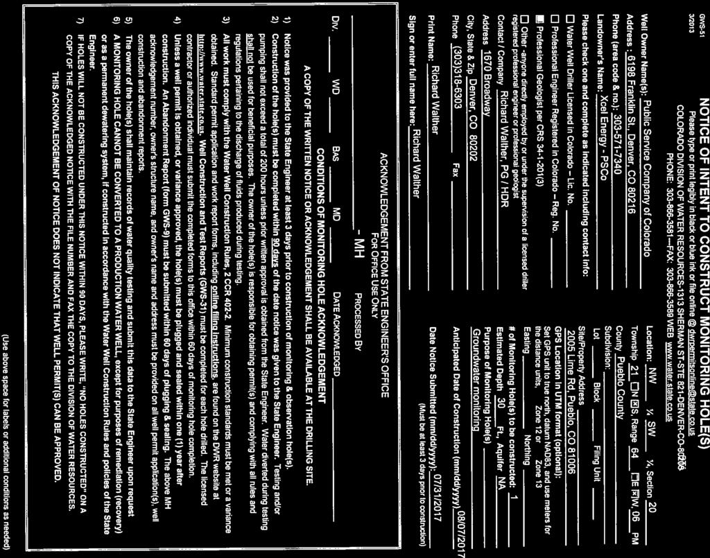
34 Xcel Energy Monitoring Well Installation Report Comanche Station Appendix D State Well Permits

35

36

37


38


39