World s largest Floating Solar Testbed Overview & Findings
|
|
|
- Lizbeth Holt
- 5 years ago
- Views:
Transcription
 National University")
1 World s largest Floating Solar Testbed Overview & Findings Dr. Thomas REINDL Deputy CEO Cluster Director, Solar Energy Systems Solar Energy Research Institute of Singapore (SERIS) National University of Singapore (NUS) June 8, 2018, ACEF Deep Dive Workshop on Floating Solar 1
 Rapid growth (now > 200 people and > 6000 m")

2 SERIS Solar Energy Research Institute of Singapore Founded in 2008; focuses on applied solar energy research Part of the National University of Singapore (NUS) Rapid growth (now > 200 people and > 6000 m 2 of space) State-of-the-art laboratories R&D focus is on solar cells, PV modules and PV systems Specialised in professional services for the PV industry ISO 9001 & ISO 17025* certified (* PV Module Testing Lab) 2
 Tandem solar cells on silicon (e.g.")
 Module certification Characterisation and")

3 Main R&D areas of SERIS Solar cells: Silicon wafer solar cells (various cell architectures) Tandem solar cells on silicon (e.g. GaAs, perovskites) Characterisation & simulation PV modules: Module development Module testing (indoor & outdoor) Module certification Characterisation and simulation PV systems: System technologies, incl. Floating PV PV grid integration Solar potential & energy meteorology Urban Solar, incl. BIPV Quality assurance of PV systems Solar thermal systems 3

4 Floating PV Testbed Project Site Plan 4

5 Floating PV Testbed Project Site Plan Floating PV Systems SolarGy / NRG Energia SolarGy / 4C Solar Phoenix Solar / C&T Sunseap / C&T Sunseap / C&T BBR Greentech / Solaris Rooftop Reference System Floating Pontoon Reservoir Upsolar / Koiné Multimedia REC / Takiron Sharp / SMCC Million Lighting/ATS / HDB 5


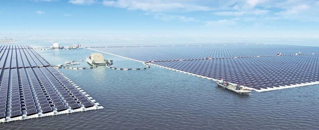
6 Floating PV Testbed Large scale FPV test-bed Side-by-side comparison of major commercial FPV technologies Detailed monitoring of all FPV systems Energy yield Cooling effect Bi-facial module Active cooling Economics, LCOE Environmental impact Water evap. losses Water quality Biodiversity 6


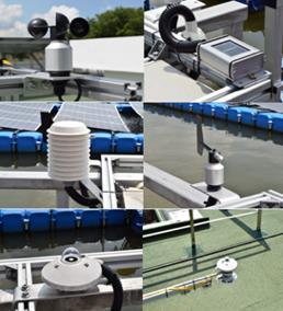


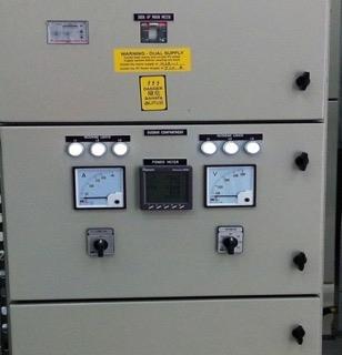
7 Floating PV Testbed Comprehensive monitoring infrastructure, with >500 parameters Meteorological station (reservoir & rooftop) PV System performance monitoring DC (PV String) AC (PV array) Motion sensor Module Temp. 7


8 Testbed operating conditions (1) Ambient temperatures T ambient on water (vs. rooftop) is consistently lower Wind Speed Wind speed on water (vs. rooftop) is generally higher 8
9 Testbed operating conditions (2) Humidity Humidity on water is generally higher 9

10 Testbed operating conditions (3) Albedo Albedo of water surface is rather small, 5~6% measured Albedo for 15 Mar 2017 Daily average 10


11 Testbed operating conditions (4) Albedo Water surface reflectivity is usually less than 10% at high incident angles (around 3 ~ 6% according to most reported measurements). Source: Wikipedia Reflectivity of smooth water at 20 C (refractive index=1.333) 11


12 Cooling effect comparison Free Standing Minimized Footprint on water Very Good convective cooling Small Footprint on water Good convective cooling Large Footprint on water Water surface partially blocked 12
13 Module cooling Cooling effect (indicated by heat loss coefficient) is dependent on floating structure. Thermal loss factors (U in W/m² k) U T cell T amb = Alpha G inc (1 Eff) U = U c + U v v v = wind speed in [m/s] Well-ventilated system Insulated system Compact, dual-pitch design 13
")
14 Testbed system performance (1) FPV system performance ratio (from Apr 2017 to Mar 2018) Up to about 10-15% higher than typical rooftop PV systems in Singapore (with PR of 75 ~ 80%) 14
 Bifacial string vs. mono-facial strings 15")
15 Daily PR (DC side) Testbed system performance (2) Bifacial modules On rooftop, bi-facial string outperforms mono-facial strings On water, bi-facial string does not seem to outperform monofacial strings, due to low albedo on water However, bi-facial might have benefit in the long term (dual glass, slower moisture ingress) Bifacial string vs. mono-facial strings 15


16 Issues encountered (1) Soiling from bird droppings Bird droppings observed on floating PV modules Partial shading Reduced performance, less energy yield Cell reserve biased, hot spots, => can lead to accelerated module degradation Solutions Part of the O&M routine (i.e. immediate actions / cleaning) Barrier methods Non-barrier methods Ultrasonic, Sonic Repeller Visual Scare Device Singapore floating PV Testbed Queen Elizabeth II reservoir, UK 16


17 Issues encountered (2) Constant movement of floating platform Mechanical stress At the joints of rigid structures On equipotential bonding tape/wire At the earthing tape connection for grounding 17

18 Issues encountered (3) Insulation faults Insulation test failure for inverters The insulation resistance (R iso ) dropped over time for floating PV strings Inverters measure R iso. When R iso does not meet the preset threshold inverters do not start. Common result: inverters start late (till the R iso limit is passed). 18
19 Other potential issues Due to proximity to water, high humidity Potential Induced Degradation (PID) Anti-PID modules preferred Corrosions (more aggravated for off-shore environments) Combiner boxes Inverters Metal supporting structures Risk of solar cables submerged in water Electrical safety, earth leakage Performance drop, system downtime Structural Anchoring / mooring needs to be carefully assessed during feasibility study Highly valuable results from this testbed shall lead to new technical standards for Floating PV (via IEC TC 82) 19


20 THE SECOND 31 Oct Nov Nov


21 Don t hesitate to contact us: thomas.reindl@nus.edu.sg More information at We are also on: 21