LARGE SCALE TRIGENERATION AND DISTRICT HEATING AND COOLING WITH RENEWABLE CONCEPTS WITHIN THE SPANISH POLYCITY PROJECT
|
|
|
- Thomas Wilkerson
- 5 years ago
- Views:
Transcription
1 POLYCITY FINAL CONFERENCE, VISIONS OF SUSTAINABLE URBAN ENERGY SYSTEMS 16th 17th SEPTEMBER 2010 LARGE SCALE TRIGENERATION AND DISTRICT HEATING AND COOLING WITH RENEWABLE CONCEPTS WITHIN THE SPANISH POLYCITY PROJECT CARLOS DAPENA, CONSORCI URBANÍSTIC DEL CENTRE DIRECCIONAL DR. JOAN CARLES BRUNO, UNIVERSITAT ROVIRA I VIRGILI


2 TABLE OF CONTENTS 1. PARC DE L ALBA POLYGENERATION SYSTEM DESCRIPTION 2. ENERGY EFFICIENCY AND RENEWABLE ENERGY MEASURES 3. STAGES OF IMPLEMENTATION 4. EXPECTED RESULTS 5. IMPLEMENTATION STAGE: ST4 PLANT EQUIPMENT DESCRIPTION MONITORING AND OPTIMISATION FIRST RESULTS DURING START-UP 6. RES CONCEPTS BIOMASS GASIFICATION PLANT SOLAR COOLING PLANT 7. ENERGY BALANCES DELTA
 PLANTS + DISCTRICT HEATING DELTA AND")

3 1. PARC DE L ALBA POLYGENERATION SYSTEM DESCRIPTION Cerdanyola (Barcelona), Spain MODULAR SYSTEM: 4 COMBINED HEAT AND POWER (CHP) PLANTS + DISCTRICT HEATING DELTA AND COOLING SYSTEM PRIMARY ENERGY: NATURAL GAS RENEWABLE ENERGY SOURCES CONTRIBUTION: BIOMASS AND SOLAR ENERGY THERMAL COOLING: SINGLE EFFECT AND DOUBLE EFFECT ABSORPTON CHILLERS
4 1. PARC DE L ALBA POLYGENERATION SYSTEM DESCRIPTION POLYGENERATION SYSTEM AND DISTRICT HEATING AND COOLING NETWORK: FACTS AND FIGURES PLANT ST-4 ST-5 ST-2 ST-3 TOTAL CO-GENERATION ENGINES (MW E ) 16,5 8, ABSORPTION CHILLERS (MW C ) 13 5, ,3 COMPRESSION CHILLERS (MW C ) HEAT RECOVERY BOILERS (MW H ) 10 4, ,5 H CONVENTIONAL BOILERS (MW H ) 5 2, ,5 DH&C NETWORK: 4 TUBES: Preinsulated pipe with diffusion barrier and built-in surveillance system. CHILLED WATER: Supply 6 ºC / Return 13 ºC HOT WATER: Supply 90 ºC/ Return 75 ºC DIAMETERS: DN150 to DN800 mm TOTAL LENGHT: 32,6 km (16,8 km 1st stage) DELTA
5 2. ENERGY EFFICIENCY AND RENEWABLE ENERGY MEASURES PLANT ST4: ENERGY EFFICIENCY MEASURES High efficiency co-generation engines: 3,35 MWel (electrical efficiency 44,9%) Single effect absorption chiller: Powered by hot water from cogeneration engines. 3 MWc (COP = 0,75) Double effect absorption chiller: Directly driven by exhaust gases 5 MWc (COP = 1,3) Thermal storage: Balance variations of cooling demand and shift peak loads m 3 of chilled water at 7ºC ( kwh) PLANT ST2: RES MEASURES Biomass gasification plant: Fuelled by wood waste from discarded furniture (e.g. plywood) or by subproducts from agricultural origin. Production: Nm3/h of syngas Adapted co-generation engine, fuelled by syngas + natural gas: 1,58 MWel Waste heat will be recovered by a combined DE/SE absorption DELTA chiller (1.650 kwc). Solar thermal plant: 475 m 2 high temperature solar thermal collectors (evacuated heat pipe) Single effect absorption chiller (100 kwc)
6 3. IMPLEMENTATION STAGES 1ST STAGE PLANT ST4: already in operation Co-generation engines: 10,05 MWel (out of 16,5) Absorption chillers: 3 MWc (SE) + 5 MWc (DE) = 8 MWc (out of 13) Compression chiller: 5 MWc Heat recovery boiler: not installed Conventional boiler: 5 MWc PLANT ST2: In engineering stage. Biomass gasification plant: Solar thermal collectors Co-generation engine: 1,58 MWel (out of 11) Absorption chillers: 1,75 MWc (out of 7) DH&C NETWORK: 16,8 km already in operation SUBSEQUENT STAGES: The Parc de l Alba polygeneration system will be implemented in several stages according to the pace of the urban development. DELTA
 Alba")

7 3. IMPLEMENTATION STAGES FIRST STAGE OF URBAN DEVELOPMENT (GREY AREAS) Alba Synchrotron m2 for scientific, technological and business use Public Equipments DELTA
8 4. EXPECTED RESULTS Stage of development Primary energy savings Reduction of CO 2 emissions First stage (plant ST-4) MWh/year Tm/year Final stage (4 plants) MWh/year Tm/year DELTA

9 5. IMPLEMENTATION STAGE: ST4 PLANT EQUIPMENT DESCRIPTION MONITORING AND OPTIMISATION OF THE PLANT FIRST RESULTS DURING START-UP
10 5. IMPLEMENTATION STAGE: ST4 PLANT OBJECTIVES Energy flows monitoring to calculate component and plant efficiencies. Reporting on current energy performance. Energy management recommendations for the optimal integration of supply and demand of energy. This task includes the use of a methodology for treatment and reconciliation of data.
11 5. IMPLEMENTATION STAGE: ST4 PLANT NATURAL GAS COGENERATION ENGINES GE-JENBACHER J620 GS-NL Natural gas engine of 20 cilindres in V 60º with pre-combustion chamber for maximum efficiency and low emissions Electrical Power: 3353 kw Electrical Efficiency: 44.9 % Total Efficiency: 87% Dimensions (h x l x w): 2.8 x 8.9 x 2.2 m Installed capacity ST4 (3 + 2 units): 16.5 MW e
12 5. IMPLEMENTATION STAGE: ST4 PLANT SINGLE-EFFECT HOT WATER DRIVEN ABSORPTION CHILLERS High efficiency (COP = 0.75) Cooling capacity (first unit, 3 NG Engines ST4): 3 MW Chilled water (in/out) : 13 / 6.5ºC
13 5. IMPLEMENTATION STAGE: ST4 PLANT EXHAUST GAS DIRECTLY DRIVEN DOUBLE-EFFECT ABSORPTION CHILLERS Thermax ED 80C High efficiency (COP = 1.3) Cooling capacity (first unit, 3 NG Engines ST4): 5 MW Chilled water (in/out) : 13 / 6.5ºC Dimensions (h x l x w): 4.3 x 9.0 x 4.4 m
14 5. IMPLEMENTATION STAGE: ST4 PLANT Optimisation environment developed for the POLYCITY project
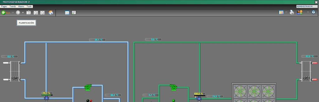
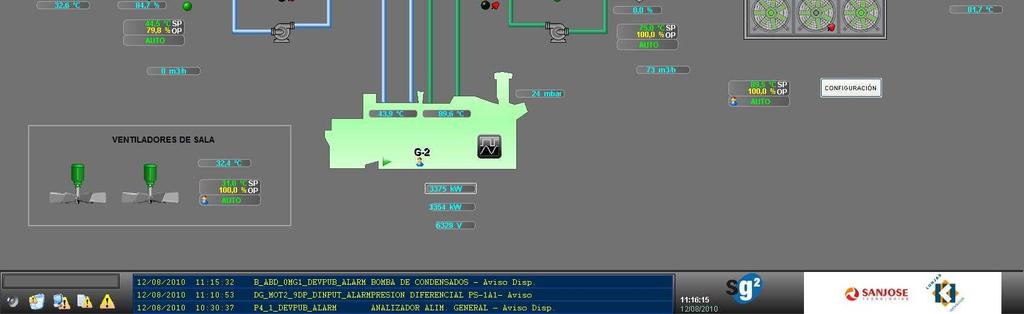
15 5. IMPLEMENTATION STAGE: ST4 PLANT
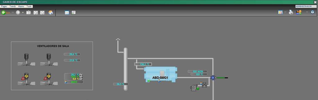
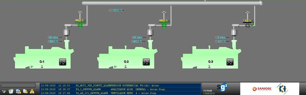
16 5. IMPLEMENTATION STAGE: ST4 PLANT
17 5. IMPLEMENTATION STAGE: FIRST RESULTS DURING START-UP COGENERATION ENGINE #2 Gas Consumption Flow rate 678 Nm 3 /h Primary energy 7322 kw Electrical power Output power 3242 kw Engine cooling Jacket inlet temp. 82 C Jacket outlet temp. 99 C Cooling water flow rate 75.5 m 3 /h Low temp. circuit 391 kw Room temperature 36 C Exhaust gas temp. 391 C Electrical efficiency 44.3 %
18 5. IMPLEMENTATION STAGE: FIRST RESULTS DURING START-UP HOT WATER DRIVEN SINGLE EFFECT ABSORPTION CHILLER Chilled water Inlet temperature 13 C Outlet temp. 6.5 C Flow rate 432 m 3 /h Cooling capacity 3275 kw Cooling water Inlet temperature 30 C Outlet temp. 37 C Flow rate 909 m 3 /h Heat rejection 7626 kw Driving heat Inlet temperature 95 C Outlet temp. 78 C Flow rate 234 m 3 /h Power capacity 4351 kw COP 0.75
19 5. IMPLEMENTATION STAGE: FIRST RESULTS DURING START-UP EXHAUST GAS DRIVEN DOUBLE EFFECT CHILLER Data with two engines running Energy consumption Exh. gas temp. from engines 393 C Exh. gas inlet temperature 349 C Exh. gas outlet temp. 164 C Exhaust gas flow rate Input power kg/h 1569 kw Chilled water Inlet temperature 10 C Outlet temperature 7.4 C Flow rate 649 m 3 /h Cooling capacity 1962 kw Cooling water Inlet temperature 28 C Flow rate 1020 m 3 /h COP 1.25
20 6. RENEWABLE ENERGY SOURCES CONCEPTS RENEWABLE ENERGY CONCEPTS: 1. BIOMASS GASIFICATION PLANT 2. SOLAR THERMAL PLANT
21 6.1 RES CONCEPTS: BIOMASS GASIFICATION PLANT 1.1 Gasification technology review: Concept The gasification process is one of the thermochemical conversions that can be used to transform the chemical energy contained in a solid fuel (like biomass) into thermal energy and electricity. The product of the gasification process is the so called Producer or Synthesis gas that is a mixture of CO, H 2 and other gases. The gasification process takes place at high temperature and needs a supply of oxidant lower than required for a combustion process. Application of the produced gas: Fuel or Raw material for chemicals. Higher electrical plant efficiency than steam or ORC biomass combustion technologies specially for small-scale plants.
22 6.1 RES CONCEPTS: BIOMASS GASIFICATION PLANT 1.1 Gasification technology review: Type of gasifiers (I) FIXED BED REACTORS UPDRAFT DOWNDRAFT CROSS FLOW The solid flows in descendent direction and the gas in ascendant direction (updraft). Both the solid and the gas have descendent flow (downdraft). The solid has descendent flow and the gas goes perpendicular to the solid.
23 6.1 RES CONCEPTS: BIOMASS GASIFICATION PLANT 1.1 Gasification technology review: Type of gasifiers (II) FLUIDIZED BED The inert solid is dragged by the gas flow. Out of the reactor is separated of the gas and it is given back to the reactor. The gas has low speed. The inert solid remain within the reactor. OTHER TYPES: Entrained Bed, Rotary kiln, Cyclonic reactor
24 6.1 RES CONCEPTS: BIOMASS GASIFICATION PLANT 1.1 Gasification technology review: Type of gasifiers (III) Basic comparasion of the main types of biomass gasifiers Fixed bed Fluid bed Scale (MWe) Granulometry (mm) Temperature (ºC) Start-up time Minutes Hours
25 6.1 RES CONCEPTS: BIOMASS GASIFICATION PLANT 1.1 Gasification technology review: Synthesis gas Gas composition (% volume) Oxidant Agent H 2 CO CO 2 CH 4 N 2 C 2 Use Air Fuel Oxygen Fuel / Chemicals Steam Fuel / Chemicals Gas composition depends on many factors: Type of biomass, gasifier type, granulometry, etc.
26 6.1 RES CONCEPTS: BIOMASS GASIFICATION PLANT 1.2 Gasification plant of Cerdanyola: Biomass availability FOREST WOOD CHIPS Good gasification properties, regular supply throughout the year. AGRICULTURE BIOMASS RESIDUES Almond shells: good gasification properties, supply not garantied for the hole year, high cost. Other: Orujillo, Olive pit, Possible gasification problems, OLD FURNITURE FROM THE BARCELONA MUNICIPALITY
27 6.1 RES CONCEPTS: BIOMASS GASIFICATION PLANT 1.2 Biomass gasification plant in Cerdanyola Wood residues gasification plant integrated in an internal combustion engine and a Single / Double Effect absorption chiller to recover simultaneously waste heat from the exhaust gas and jacket water. 1 MWe power capacity. Biomass Gasification Plant Gas Cleaning process
28 6.1 RES CONCEPTS: BIOMASS GASIFICATION PLANT 1.2 Gasification plant of Cerdanyola: Alternative designs OPTION A - Gasification capacity: 1000 kg/h - Gasification technology: Bubble fluidised bed - Natural gas engine power: 1210 kw

29 6.1 RES CONCEPTS: BIOMASS GASIFICATION PLANT 1.2 Gasification plant of Cerdanyola: Alternative designs OPTION B - Gasification capacity: 750 kg/h - Gasification technology: Fixed bed - Downdraft - Natural gas engine power: 590 kw
30 6.1 RES CONCEPTS: BIOMASS GASIFICATION PLANT 1.2 Gasification plant of Cerdanyola: Alternative designs OPTION C - Gasification capacity: 1800 kg/h - Gasification technology: Fixed bed - Downdraft - Natural gas engine power: 1512 kw
31 6.1 RES CONCEPTS: BIOMASS GASIFICATION PLANT 1.3 Modelling of the biomass gasification plant Flowsheet of the gasification process in the Aspen Plus process simulator
32 6.1 RES CONCEPTS: BIOMASS GASIFICATION PLANT 1.3 Modelling of the biomass gasification plant First results of the model: agreement with published data. The next step is the tuning of model parameters using real plant data. The validated model will be adapted and used in the Cerdanyola plant. 70 Evolution of the raw gas composition produced at the gasifier 60 Syngas composition (% molar) N2 CO CO2 H2 H2O CH Air flow (m3/h)
33 6.1 RES CONCEPTS: BIOMASS GASIFICATION PLANT 1.3 Modelling of the biomass gasification plant
 design of the sorption cooling system (optimal tilt of solar collectors, volume")
34 6.2 RES CONCEPTS: SOLAR COOLING PLANT Energy analysis of the solar cooling plant Use of renewable solar thermal energy to produce chilled water instead of electricity or fossil fuels. Energy analysis of the solar cooling plant: comparison of design alternatives (type of chillers, solar collectors, etc) design of the sorption cooling system (optimal tilt of solar collectors, volume of the thermal storage, ) annual performance analysis
35 6.2 RES CONCEPTS: SOLAR COOLING PLANT Energy analysis of the solar cooling plant Modelling performed with TRNSYS
36 6.2 RES CONCEPTS: SOLAR COOLING PLANT Energy analysis of the solar cooling plant Summary of the main results Chiller Type ABSORPTION ADSORPTION Type of solar collector Solar field (gross area) Annual heat produced Specific annual heat produced Annual cold production Specific annual cold production m 2 MWh kwh/m 2 MWh kwh/m 2 FPC U PIPE HEAT PIPE U PIPE FPC U PIPE HEAT PIPE U PIPE Best option: Evacuated tubes collectors with an absorption chiller (~100 kw).
37 Global energy balances for the ST4+ST2 plants scenario GLOBAL ENERGY BALANCES


38 THANK YOU FOR YOUR ATTENTION!