APPENDIX C. STORMWATER STRUCTURAL BMP DESCRIPTIONS
|
|
|
- Amos Garrett
- 5 years ago
- Views:
Transcription
1 APPENDIX C. STORMWATER STRUCTURAL BMP DESCRIPTIONS DETENTION PONDS Historically, detention ponds were designed for stormwater quantity control only. Extended detention of stormwater, with slow release over time, maintains flow rates and frequencies similar to those under natural, predevelopment hydrologic conditions. This controlled release reduces streambank erosion and flooding of downstream areas. Today, however, ponds designed for water quality enhancement as well as detention are commonplace. Properly designed detention ponds can provide effective treatment of pollutants contained in stormwater by providing quiescent conditions that allow particulates to settle. Extended detention ponds are designed to either empty completely or dry out between storms ( dry ponds) or to maintain a permanent pool ( wet pond). Permanent pools help to dissipate energy and prevent scour of the pond bottom. Pools also provide sites for aquatic vegetation to grow, increasing sedimentation and pollutant uptake, similar to wetlands. The City of Medford currently requires that all new commercial and industrial development in the Midway Drainage and Elk Creek Basins include detention facilities. Extended detention ponds remove pollutants primarily by gravitational settling. Their effectiveness is determined by detention time and the fraction of annual runoff volume that is effectively detained. Vegetation provides physical filtration of sediment and biological uptake of dissolved pollutants. Well-maintained detention ponds can remove the majority of suspended sediments and particulate pollutants in stormwater. Design factors that can improve pollutant removal include long detention times, a permanent pool area, small treatment volumes and incorporation of a constructed wetland in the lower stage. Applicable Locations: Larger Commercial or residential projects where land is available to treat a large drainage area. These are typical City CIP projects to address existing drainage problems. C-1

2 City of Medford Stormwater Management Plan Figure C-1. Wet Extended Detention Pond (Source Maryland Stormwater Design Manual) C-2
3 APPENDIX C. STORMWATER STRUCTURAL BMP DESCRIPTIONS DETENTION VAULTS/TANKS/PIPES Detention vaults, tanks, and pipes are underground storage facilities used to collect and store surface water. These facilities are used primarily for stormwater quantity management in drainage areas containing less than 3 acres of impervious area. They are typically constructed of reinforced concrete (vaults) or corrugated metal pipe (tanks or pipes). A permanent pool of water is often maintained in wet tanks and vaults to provide quiescent settling conditions for pollutant removal. Pollutant removal processes in tanks and vaults are for the most part limited to removal of large sediment particles. Pollutant reduction occurs through gravity settling of particulates. Due to a lack of vegetation, detention vaults are incapable of removing dissolved pollutants. Wet vaults and tanks can remove only a small fraction of the sediment load and have insufficient volume to provide efficient removal of smaller soil particles. Their underground location precludes biological assimilation processes. Applicable Locations: In areas where flooding is a problem or where the downstream portion of the storm system is not large enough to handle flows all at once. Typically used for smaller commercial developments however, detention vaults do not provide sufficient water quality treatment and additional source control measures should be required. C-3
4 City of Medford Stormwater Management Plan Figure C-2. Detention Vault (City of Portland, Stormwater Management Manual) C-4


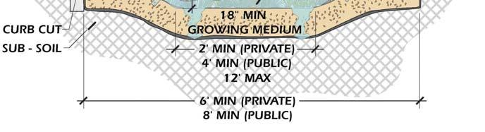
5 APPENDIX C. STORMWATER STRUCTURAL BMP DESCRIPTIONS INFILTRATION BASINS/TRENCHES/BIORETENTION Infiltration can be provided by a variety of facilities, including dry wells, vaults, ponds, roof downspout systems, porous pavement, and modular pavement. The most common infiltration facilities are basins and trenches. Infiltration technologies use the interaction of chemical, physical, and biological processes between soil and water to filter sediments and soluble pollutants from runoff. As the stormwater percolates into the ground, fine material suspended in the stormwater is captured in the soil. The resulting treated runoff percolates through to the groundwater rather than to surface water. They have a high treatment efficiency and the ability to recharge groundwater; however, proper siting, design, construction, and maintenance are critical in order to maximize their effectiveness, avoid clogging problems, avoid accumulations of metals, and prevent groundwater contamination. Infiltration basins are impoundments where incoming stormwater runoff is stored until it gradually exfiltrates through the soil of the basin floor. A conventional infiltration trench is a shallow, excavated trench that has been backfilled with stone to create an underground reservoir. Stormwater runoff diverted into the trench gradually exfiltrates from the bottom of the trench into the subsoil and eventually into groundwater. Enhanced infiltration trenches have extensive pretreatment systems to remove sediment and oil. Figure C-3. Infiltration Trench (Source Northern Virginia BMP Handbook) Bioretention includes a combination of biofiltration and infiltration. A bioretention facility primarily consists of a porous planting soil covered with a mulched layer and vegetated to encourage evapotranspiration. Stormwater sheet flows to the facility and is allowed to pond to provide storage and allow for slow infiltration. Stormwater can either be collected in an C-5

 Infiltration facilities improve water quality by")

6 City of Medford Stormwater Management Plan underdrain or allowed to infiltrate directly into the native soil. A vegetated buffer strip can also be used for additional treatment prior to stormwater entering the facility. Figure C-4. Bioretention (Source Maryland Stormwater Design Manual) Infiltration facilities improve water quality by percolating runoff through soil. Organic matter and small amounts of clay adsorb both soluble and insoluble pollutants as the runoff travels through the soil. Pollutant removal mechanisms include adsorption, straining, and microbial decomposition in soil. Vegetative cover improves pollutant removal through filtration, trapping, and biological uptake. C-6
7 APPENDIX C. STORMWATER STRUCTURAL BMP DESCRIPTIONS Actual performance data on infiltration facilities is rare; however, basins and trenches are believed to have high removal efficiencies for particulates and moderate removal for soluble pollutants. Applicable Locations: Commercial or residential projects or small Citywide basins. Not suitable in locations where the depth to groundwater is less than 5 feet. Areas of low permeability may require facilities to be constructed using soils that allow infiltration and collected stormwater at the downstream end with an underdrain. C-7


8 City of Medford Stormwater Management Plan CATCH BASINS AND INLETS Grated and curb inlet type catch basins are designed to catch debris carried by street surface runoff. Most trapped catch basins for enclosed stormwater systems have a few feet of storage in the bottom that never drains to an outflow pipe. This permanent storage area is intended to trap sediments, debris, and other particles that can settle out of stormwater, to prevent clogging of downstream pipes and washing of these solids into receiving waters. Catch basin inserts can be installed to filter stormwater entering the catchbasin. Inserts typically consist of a suspended structure with filter medium such as sand, carbon, or fabric. Inserts have a small volume and require frequent clean out. They are not practical for citywide use in all catch basin; however, they can be used temporary sediment control and pretreatment at construction sites and may be appropriate in small drainage areas for specific target pollutants. Catch basins collect large sediment particles and debris. Large debris is collected on the grate while smaller nonfloatable debris, grit, and sediment that pass through the grate are caught in the sump portion of the catch basin. Well-maintained catch basins remove the majority of suspended sediments and particulate pollutants in stormwater. The small size of trapped catch basins limits pollutant removal to larger particles such as grit and sediment. Sediment deposits must be removed at least twice a year to prevent sediment resuspension. Applicable Locations: Temporary sediment control and pretreatment at construction sites, and may be appropriate in small drainage areas for specific target pollutants. Figure C-5. Catchbasin Insert C-8
9 APPENDIX C. STORMWATER STRUCTURAL BMP DESCRIPTIONS MANUFACTURED FACILITIES Innovative manufactured systems are continually being developed as BMPs to reduce specific pollutants in stormwater runoff. Such facilities include oil/water separators, catch basin inserts, multichamber treatment trains, and water quality vaults. Two general types of oil/water separators are used for stormwater treatment: conventional gravity API (American Petroleum Institute) separators, and coalescing plate separators (CPS). Both types are used to treat stormwater runoff from high-use developments and facilities that produce relatively high concentrations of oil and grease. A spill control separator is an underground vault with a T outlet and is effective at retaining only small, undiluted spills not normally associated with stormwater. Gravity (API) oil/water separators consist of vaults, typically constructed of steel or concrete, with multiple chambers separated by baffles extending down from the top, blocking oil flow out of the vault and reducing turbulence. Baffles may also be installed at the bottom of the vault to trap solids and sludge that accumulate over time. Oil absorbent pillows and floating or mechanical oil skimmers are often installed in the vaults to remove the separated oil. Coalescing plate separators are typically manufactured units consisting of a baffled vault containing several inclined corrugated plates bundled together. The plates may be made of fiberglass, stainless steel, or polypropylene. The closely spaced plates improve the hydraulic conditions for oil removal. CPS-separators are often smaller than API separators. Oil/water separators employ the mechanism of oil, being lighter than water, rising to the surface and being periodically removed. They are designed to remove free oil, and are not generally effective in separating oil that has become either chemically or mechanically emulsified and dissolved in water. They must be cleaned frequently to keep accumulated oil from escaping during storms. A multi-chamber treatment train (MCTT) consists of a series of treatment units that mimic those found in wastewater treatment plants. Pollutant removal mechanisms vary with each type of treatment facility. Applicable Locations: In commercial or residential area; to treat runoff from roads and parking areas, small footprint and underground construction allows for installation in areas where land availability is limited. These facilities can also be used as fore-bays in wetland treatment ponds. C-9


10 City of Medford Stormwater Management Plan Figure C-6. American Petroleum Institute Oil-Water Separator Figure C-7. StormFilter Leaf Compost Filter C-10
11 APPENDIX C. STORMWATER STRUCTURAL BMP DESCRIPTIONS BIOFILTERS (SWALES, FILTER STRIPS) Biofiltration swales are long, gently sloped conveyance ditches with flattened side slopes, designed to remove pollutants by filtering stormwater through vegetation. Grass is the most common vegetation, but other vegetation types, such as emergent wetland species, are often used, depending on site conditions. Swales are designed to distribute flow evenly across the entire width of the densely vegetated bottom, and may employ check dams and wide depressions to increase runoff storage and promote greater settling of pollutants. Often providing both treatment and conveyance of peak design flows, swales can reduce development costs by eliminating the need for separate conveyance systems. Biofiltration swales are best applied on a relatively small scale (generally less than 5 acres of impervious surface). They work well along roadways, driveways, and parking lots. Filter strips are vegetated sections of land designed to accept runoff as overland sheet flow from upstream development. They may adopt any naturally vegetated form, from grassy meadow to emergent wetland to small forest. The dense vegetative cover facilitates pollutant removal. Filter strips differ from swales in that swales are concave conveyance systems, while filter strips are located parallel to the contributing area, have fairly level surfaces, and provide treatment of sheet flow. Biofilters remove pollutants primarily by the filtering action of vegetation trapping particulates. Other pollutant removal mechanisms include sediment deposition in lowvelocity areas, infiltration into the subsoil, and surface adhesion of pollutants to vegetation, biological assimilation, and soil adsorption. Well-designed and -maintained biofilters have been known to remove the majority of suspended sediments and particulate pollutants in stormwater. Swales appear to be more effective at removing metals than nutrients; however, accumulations of trace metals in biofilter sediments may occur. Resuspension or remobilization of nutrients may occur, particularly if maintenance is not performed regularly. Applicable Locations: Parking lots, residential or small business streets. Treats stormwater from small drainage areas and provides detention. C-11


12 City of Medford Stormwater Management Plan Figure C-8. Vegetated Swale (Source City of Portland Stormwater Management Manual) Figure C-9. Grassy Swale (Source City of Portland Stormwater Management Manual) C-12
13 APPENDIX C. STORMWATER STRUCTURAL BMP DESCRIPTIONS CONSTRUCTED WETLANDS, WET PONDS A constructed wetland is a shallow, sometimes intermittent, pool constructed to provide suitable conditions for the growth of wetland plants for the purposes of stormwater management. Constructed wetlands often consist of a combination of shallow trenches, marshes, and ponded sections, with a wide variety of vegetation types. Stormwater wetlands are designed to maximize pollutant removal through uptake by plants, retention, and settling. Created wetlands, as distinct from constructed wetlands, are considered mitigation for an activity, and are not used for stormwater management. They are treated as natural wetlands, and are subject to the same protections. See Streams & Wetlands. A wet pond is a basin with a permanent pool of water, normally too deep for rooted wetland plants but often containing aquatic vegetation, with wetland species growing along the margins. The pool depth typically ranges from three to six feet, providing dead storage of stormwater. Wet ponds are often constructed to address both water quality and reduction of runoff peaks. Both types of facilities can be sources of wildlife habitat, enhancing the aesthetic value of an area and providing opportunities for passive recreation and public education. Constructed wetlands, natural wetlands, and wet ponds remove pollutants through gravitational settling, wetland plant uptake, adsorption, filtration, and microbial decomposition. Deep-water areas such as wet ponds improve the sedimentation, photosynthetic, biological, and chemical removal of pollutants. The actual pollutant removal efficiency of any constructed wetland or wet pond depends on many variables, most of which are poorly understood in terms of actual facility performance. Numerous field studies indicate these systems are able to remove the majority of the settleable solids and particulate pollutants in stormwater. Applicable Locations: Larger commercial or residential projects or regional CIP projects where land is available to treat a large drainage area. C-13


14 City of Medford Stormwater Management Plan Figure C-10. Shallow Wetland (Source Maryland Stormwater Design Manual) C-14

15 APPENDIX C. STORMWATER STRUCTURAL BMP DESCRIPTIONS Figure C-11. Wet Pond (Source Maryland Stormwater Design Manual) C-15
16 City of Medford Stormwater Management Plan STREAMS AND WETLANDS Natural streams and wetlands perform a variety of vital functions related to stormwater conveyance, attenuation, groundwater recharge, and treatment. Their existence in urban settings however, does not imply their use as receivers and conveyors of additional and often polluted stormwater runoff. Streams and wetlands are affected by development even if not specifically used in stormwater management. Therefore, the management of natural streams and wetlands must anticipate these incidental effects to protect their general functioning. Natural streams and wetlands are sensitive to changes in stormwater flow velocities, volumes, and duration. Impervious area and land use changes within the basin affect not only surface water runoff, but also shallow and deep groundwater, which are often critical to the maintenance of base flow and wetland conditions. Many seemingly unrelated stormwater management activities eventually affect natural systems. It is therefore important to fully evaluate the potential and long-term effects of all activities in order to eliminate, minimize, mitigate, or monitor their impact on streams, wetlands, and all natural systems. These inevitable effects of urbanization and stormwater management necessitate specific maintenance activities in streams and wetlands to preserve their ecological integrity, function, and value. Streams and wetlands, in conjunction with their riparian or buffer areas, remove pollutants through physical mechanisms of sedimentation, filtration, and adsorption. They are also capable of removing pollutants through biological and chemical mechanisms such as plant adsorption, uptake and metabolism by bacteria and plants, precipitation, and adsorption by soil particles. The pollutant removal efficiency of natural streams and wetlands is widely variable due to the variety of physical, chemical, and biological characteristics and configurations in these systems. In addition, studies have shown that removal rates for phosphorus may, at times, be negative due to biological degradation. Biological degradation typically occurs during the winter months, phosphorus is not a concern in Bear Creek during this time. Applicable Locations: Where natural streams and wetlands exist. C-16
17 APPENDIX C. STORMWATER STRUCTURAL BMP DESCRIPTIONS FILTERING Stormwater filtering systems have been used successfully in ultra-urban areas due to their relatively small footprint and moderate physical and head drop requirements. A number of filtering systems have been developed for use in heavily urbanized areas. Filters typically contain the same basic components: a sedimentation area to retain the largest particles and a chamber containing the filter medium that captures soluble pollutants. Vegetated rock filters have long been used to treat wastewater. A typical design consists of a series of tanks filled with several feet of aggregate. A typical sand filter consists of a flow spreader, sand bed, and an underdrain. Pretreatment is required for removal of larger particulates and reduce velocities. Sand filters can be used in residential, commercial and industrial area, where debris, large particulates, and oil & grease will not clog the filter. Sand filters can be located either above or below ground. Media filters include media such as leaf compost, pleated fabric, activated charcoal, perlite, amended sand and perlite, and zeolite in a cartridge. Stormwater is routed through the media cartridge for treatment. Pretreatment may be required in areas of high suspended solids and hydrocarbon loading. Pollutant removal occurs by filtration or adsorption onto the filter media. Treatment using a vegetated rock filter is primarily by biological action and root uptake. Applicable Locations: This is a great source control for any location however is very suited for commercial and industrial areas where a limited area footprint is available. C-17


18 City of Medford Stormwater Management Plan Figure C-12. Downspout Sandfilter (Source City of Portland Stormwater Management Manual) Figure C-13. Flow through Planter (Source City of Portland Stormwater Management Manual) C-18


19 APPENDIX C. STORMWATER STRUCTURAL BMP DESCRIPTIONS Figure C14. Underground Sand Filter (Source Maryland Stormwater Design Manual) C-19