Stormwater Management Practice Notes. District Plan Change 22 (Decision Notice Version)
|
|
|
- Colin Robert Atkinson
- 5 years ago
- Views:
Transcription


1 Stormwater Management Practice Notes for District Plan Change 22 (Decision Notice Version)
2 Stormwater Management Practice Notes List of Practice Notes Stormwater Management Practice Notes: NSC 01: Stormwater Mitigation Overview NSC 02: Calculating Site Imperviousness NSC 03: Permitted Activity Route NSC 04: Controlled Activity Route NSC 05: Single Purpose Rain Tanks for Residential Applications NSC 06: Dual Purpose Rain Tanks for Residential Applications NSC 07: Detention Tanks NSC 08: Single Purpose Rain Tanks for Non-residential Applications NSC 09: Dual Purpose Rain Tanks for Non-residential Applications NSC 10: Bio-Retention (Rain gardens) NSC 11: Pervious Paving NSC 12: Green Roofs Page 2 of 2
3 Stormwater Management Practice Note NSC 01: Stormwater Mitigation Overview 1.1 Introduction This set of stormwater management practice notes has been developed to assist people in understanding the on-site stormwater mitigation requirements which were incorporated into the District Plan as part of plan change 22. They are relevant to all urban areas of the city except the Long Bay Structure Plan area and Okura. These new stormwater requirements concentrate on stream erosion and flooding and are in addition to the Proposed Auckland Regional Plan: Air Land & Water (Chapter 5) requirements which can be achieved using the ARC Technical Publication No 10 (TP10), Design Guidelines Manual: Stormwater Treatment Devices, The TP10 guidelines are minimum requirements and additional requirements are a function of the sensitivity of the receiving environment. You are advised to check the ARC s stormwater discharge requirements and obtain any required consent from them. Note that any development with an impervious area of more than 1000 m 2 is likely to require consent from the ARC. 1.2 Descriptions of the Five Stormwater Management Areas (SMAs) The city has been divided into five Stormwater Management Areas to better manage the effects of stormwater runoff from urban development. The different Stormwater Management Areas (SMAs) are based on the sensitivity of the receiving environment. These supersede the Approved Stormwater Outfall Zones which were previously used for this purpose. Stormwater coastal effects on beaches and cliffs are also important and stormwater still needs to be discharged to an approved stormwater outfall in a manner which complies with Clause E1 of the Building Code. The locations of these areas are shown on seven Stormwater Management Area maps which were incorporated into the District Plan as part of Plan Change 22. They can also be obtained from: The council s website at: or Shown on your LIM or PIM, or The council Help Desk at Environmental Services, 521 Lake Road, Takapuna The reason for incorporating this process into the District Plan is so that property owners are made aware of stormwater management requirements early on in the development process rather than at the building consent stage as was the practice under the Approved Outfalls Policy. These management areas are for controlling the average annual volume of stormwater runoff, as well as the peak flows from a range of rainfall events between a 3 month event and the 10% AEP rainfall event, so that these flows are closer to the flows that would have occurred before development took place.
4 Stormwater Management Practice Note NSC 01 Stormwater Mitigation Overview The threshold for new impervious area without on-site stormwater mitigation has now been set very low (at 15%) in the more sensitive catchments (SMAs 1, 2 and 3) and very few developments are likely to fall within this category. It is expected that most new developments will be required to provide on-site stormwater mitigation. In addition to this the threshold for maximum impervious area has also been reduced in some SMAs. This means that most new development in SMAs 1, 2 and 3 will be required to provide some form of on-site stormwater mitigation which may consist of rain tanks, bioretention /(raingardens), pervious paving or green roofs, or a combination of the above devices tailored to suit your site and location. A set of practice notes has been developed to assist you in deciding the appropriate level of stormwater mitigation for your site and the minimum design requirements. New development in SMA 4 is required to provide on-site stormwater detention to ensure that post development stormwater flows are no larger that they were before the development took place. Note that regardless of any on-site stormwater mitigation provided, stormwater will still need to be discharged to an approved stormwater outfall in accordance with Clause E1 of the Building Code and in a manner which does not cause nuisance. 1.3 The Process The process is a function of: The Stormwater Management Area (SMA) (see Table 8.1: Stormwater Management Areas and SMA Maps in Appendix 11) Residential, Structure Plan or Business zone Residential or non-residential activity The maximum site imperviousness (See Rules and Table 8.2) The activity status (see On-Site Stormwater Management Rules ) The on-site stormwater management and performance standards (See Appendix 8H) Existing treatment devices (e.g. if there is an existing NSCC Approved stormwater management device) The following flow diagram describes the process and associated stormwater requirements for a Permitted Activity in four primary situations: 1. Permitted Residential Activity, SMA 1, 2 and 3 2. Permitted Non-Residential Activity, SMA 1, 2 and 3 3. Permitted Residential or Non-Residential Activity, SMA 4 4. Permitted Residential or Non-Residential Activity in SMA 5 has no requirements 1-2
5 Stormwater Management Practice Note NSC 01 Stormwater Mitigation Overview Figure 1.1 : Flow Diagram for permitted Activity Routes Determine your SMA from District Plan Maps Appendix 11 or GIS Is proposal within maximum site Impervious Area Allowance from Table 8.2 (Practice Note NSC 02) Yes No Resource Consent Required Rules or Business = Limited Discretionary Residential = Discretionary Only required to meet ARC requirements Determine on-site mitigation requirements based on which SMA your site is in. SMA 5 Required to provide onsite detention Rule (Practice Note NSC 03) Route C SMA 4 Yes Have all downstream issues been resolved? No Yes Required to provide reduced on-site mitigation Rule (Practice Note NSC 03) Route A SMA 3 Required to fully mitigate 60% of new impervious surface (Table 8.3) Residential Does your site drain directly to an Approved Stormwater Detention Facility? SMA 2 Required to fully mitigate 70% of new impervious surface (Table 8.3) Proposed Activity? No Yes Required to provide full on-site mitigation Rule (Practice Note NSC 03) Route B Required to provide reduced on-site mitigation Rule (Practice Note NSC 03) Route A SMA 1 Required to fully mitigate 80% of new impervious surface (Table 8.3) Non-Residential Does your site drain directly to an Approved Stormwater Detention Facility? No Required to provide full on-site mitigation Rule (Practice Note NSC 03) Route B 1-3
6 Stormwater Management Practice Note NSC 01 Stormwater Mitigation Overview The process is designed to provide a number of different routes to achieving the required on-site stormwater mitigation. 1. The easy route There is a Permitted Activity route where applicants can select standard mitigation solutions. These are in most cases slightly larger than required, but they reduce the design requirements, uncertainty and need for a resource consent. It is anticipated that most applicants will choose this route. 2. The medium route this route requires resource consent as a Controlled Activity but the applicant is able to tailor on-site stormwater management to suit their particular development. The applicant will need to show how they achieve the required on-site stormwater mitigation. 3. The difficult route this route requires resource consent as a Limited Discretionary Activity. This route is provided for those situations where an applicant is unable to provide adequate on-site stormwater management. In this situation a best practicable solution would need to be provided. 4. The very difficult route an applicant may apply for resource consent where the impervious area threshold is exceeded. 1.5 North Shore City Stormwater Management Practice Notes To assist the design process a number of Practice Notes have been developed which are listed below: Stormwater Management Practice Notes: NSC 01: Stormwater Mitigation Overview NSC 02: Calculating Site Imperviousness NSC 03: Permitted Activity Route NSC 04: Controlled Activity Route NSC 05: Single Purpose Rain Tanks for Residential Applications NSC 06: Dual Purpose Rain Tanks for Residential Applications NSC 07: Detention Tanks NSC 08: Single Purpose Rain Tanks for Non-residential Applications NSC 09: Dual Purpose Rain Tanks for Non-residential Applications NSC 10: Bio-Retention (Rain gardens) NSC 11: Pervious Paving NSC 12: Green Roofs These practice notes are available on the North Shore City Council web site: 1-4
7 Stormwater Management Practice Note NSC 02: Calculating Site Imperviousness This practice note has been developed to promote consistency when calculating site imperviousness. It has been developed for use with District Plan Rule and is relevant to all Residential, Business and Structure Plan areas of the city but excluding Long Bay. 2.1 Impervious Area Limits Rule sets the following limits on total site imperviousness: Table 2.1 : Maximum Impervious Area Limits SMA Residential & Structure Plan Zones (excluding Mixed Use Overlay Area*) Business Zones & Structure Plan Zone Mixed Use Overlay Area* 1 50% 80% 2 60% 90% 3 60% 90% 4 70% 100% 5 70% 100% Note: This table is derived from Table 8.2 in the District Plan 2.2 Definitions The following District Plan definitions are relevant: Impervious Area Means any part of a site which is covered in a surface constructed of materials which are resistant to water passing through them and includes any area which: a. Falls within the definition of building coverage b. Is paved with concrete, asphalt, pervious paving, roofed areas and decks c. Provide driveways and parking areas (including unpaved and metalled surfaces) d. Is occupied by swimming pools But does not include: Paths and paving stones less than 1 metre in width provided they are separated from other impervious areas by at least 1 metre (including strip driveways with 0.5 metres between strips)
8 Stormwater Management Practice Note NSC 02 Calculating Site Imperviousness Retaining or garden walls within garden / lawns Rain tanks up to 5m 2 in area Note: Pervious paving, green roofs, uncovered wooden slated decks and swimming pools are counted as impervious area in terms of the calculation of total site imperviousness. However, the perviousness of these structures will be taken into account when calculating mitigation of stormwater runoff under Rule Net Site Area In relation to a rear site means the difference in area between the total area of the site (gross area) and the area of its entrance strip. In relation to a front, corner or through site, net site area, gross site area and area shall have the same meaning. Road Corner site Front site Corner site Road Front site Rear site Entrance strip Front site Rear site Through site Front site Road Corner site Front site Corner site Road Permeable Area Means any part of a site which is grassed or planted in trees or shrubs and is capable of absorbing water. It does not include any area which falls within the definition of impervious area. Self Mitigating Surfaces Means surfaces which while counted as impervious in terms of total site impervious area are able to mitigate stormwater runoff to an acceptable level, and include pervious paving, green roofs, uncovered slatted wooden decks over natural ground and swimming pools. 2-2
9 Stormwater Management Practice Note NSC 02 Calculating Site Imperviousness 2.3 Impervious Areas not Requiring On-site Stormwater Mitigation The following areas are not required to provide on-site stormwater mitigation but are included in the calculation of total site imperviousness and may not cause site imperviousness to exceed the maximum impervious threshold in Table 2.1 above (see Rule Table 8.2). Small additions and accessory buildings including paved areas, up to an aggregate area of 25m 2. It was decided to allow minor additions of impervious area, (less than 25m 2 ) to proceed without the need for on-site mitigation. Note that this is not an allowance but a threshold above which the rule kicks in. If an impervious area exceeds 25m 2 then the whole area is to be mitigated. Pervious paving Uncovered slatted timber decks over natural ground Swimming pools Green Roofs Note that stormwater runoff from these areas still needs to be disposed of in a manner which complies with Clause E1 of the Building Code and does not create a nuisance to neighbouring properties. 2.4 Site area for measuring Total Site Imperviousness The way in which total site imperviousness is calculated will differ depending on whether the development is on a delineated area or a separate title, and also whether the lot is a rear lot, front lot, corner lot, through lot or access lot. Separate Title For a separate title the measurement of total site imperviousness shall be based on the net site area. Rear lots will therefore exclude the access strip. Cross Lease In the case the case of a cross lease, the covenant area or delineated area shall be counted as the site area for the purposes of rule and Where clear delineated areas are not shown, or unclear, the parent site shall be used. Unit Title In the case of a Unit Title subdivision the impervious area for a multi-unit development, where individual titles have not yet been created will be calculated on the area of the parent site. Any later modifications involving individual units will be on the Unit entitlement and Unit area and exclude any area of the common property. Jointly Owned Access Lots (JOAL) In the case of JOAL s or private roads, these are not included in the calculation for total site imperviousness, they are to be considered as roads and are therefore not subject to Rule or 8.4.8, however appropriate stormwater mitigation is required at subdivision stage. Right of Way (ROW) Where a ROW has been created for access purposes to a rear lot then the area of the ROW is included in the parent site area. 2-3
10 Stormwater Management Practice Note NSC 02 Calculating Site Imperviousness Only the coloured area on the figure below needs to be used for calculating total site imperviousness and any on-site stormwater mitigation requirements. Lot A Lot B Lot C Lot D Road JOAL JOAL or Private Road Lot E Lot F Lot G Lot H Lot A Lot B Lot C Rear Lot with Access Strip & ROW Lot D Lot E Lot F Lot A Lot B Rear Lot with ROW ROW Road Lot A Lot B Rear Lot with pan handle Covenant Area A Covenant Area B Cross Lease with delineated areas Common Unit A entitlement Unit A Common Unit Title Subsequent development Unit B Unit B entitlement 2-4
11 Stormwater Management Practice Note NSC 02 Calculating Site Imperviousness 2.5 Measuring Total Site Imperviousness Table 2.2 : Areas Included or Excluded from Total Site Imperviousness Type of Area Included Condition or Comment Roof Areas Yes The roof area and not the building footprint must be measured. Green Roofs Yes Self Mitigating Surface. See below. Paved Areas Yes All paved areas not exempt below. Wooden Decks Yes Self Mitigating Surface. See below. Pervious Paving Yes Self Mitigating Surface. See below. Unpaved Parking / Metalled Driveway Yes Garden Sheds Yes See below. These areas with metal or shell are highly compacted and do not allow soakage. Swimming Pools Yes Self Mitigating Surface. See below. Rain Tanks No If less than 5m 2 in area. Paths less than 1m Wide Strip Driveways Grassed and Garden Areas Pebble Gardens No No No No As long as there is at least 1 metre of permeable area on both sides. As long as there is at least 1 metre of permeable area on both sides and 0.5 metre in middle. Provided the areas are not used for parking or traffic access. 2-5
12 Stormwater Management Practice Note NSC 02 Calculating Site Imperviousness Paved Areas All paved areas not exempted by the above definitions must be taken into account when calculating total impervious areas. Roof Area The total roof area including eaves is to be measured not just the building footprint. For existing roofs, measure the plan area of the roof at ground level below the edges of the roof (including eaves). For proposed buildings, the area can be calculated from the roof plan drawings (not the wall floor plan dimensions) as these include the additional area of the eaves. Green Roofs Green roofs are measured in the total impervious area calculation but are considered to be a mitigation method so is accounted for in achieving the required mitigation. These are classified as self mitigating surfaces and do not require additional mitigation. This is only if the green roof has been designed and constructed to the required standards (see Stormwater Management Practice Note NSC 12). Wooden Decks Wooden decks are counted as impervious as there is little chance for vegetation to grow beneath the deck. They are classified as self mitigation surfaces if they are slatted/allowing water to pass through and located above natural ground and you are not required to provide any additional mitigation for these areas. Pervious Paving Pervious paving is measured in the total impervious area calculation but is considered to be a mitigation method so is accounted for in achieving the required mitigation. These areas are classified as self mitigating surfaces and do not require additional mitigation. This is only if the pervious paving has been designed and constructed to the required standards (see Stormwater Management Practice Note NSC 11). Unpaved Parking / Metalled Driveways Unpaved parking areas with compacted ground, metal or shell etc are considered as impervious and must be included in the impervious area calculation. Rain Tanks Rain Tanks with a plan surface area of less than 5m 2 imperviousness calculation. can be excluded from the total site 2-6
13 Stormwater Management Practice Note NSC 02 Calculating Site Imperviousness Garden Sheds Garden sheds or ancillary buildings with a roof area of less than 10m 2 are included in the impervious area calculation, but may not be required to provide stormwater mitigation if constructed or installed at a later date. Paths less than 1m Wide Paths of less than 1 metre in width with vegetation on both sides may be excluded from the total impervious area calculation, (unless they are within 1 metre of other impervious areas). Swimming Pools The area of a swimming pool is considered as impervious because the water is unable to infiltrate into the ground, but is not required to provide mitigation because of the storage volume provided between the normal pool level and the overflow level. A paved area of no more than 1 metre in width surrounding the swimming pool may be considered as part of the pool. Strip Driveways Strip driveways may be excluded from the total site imperviousness calculation as long as the strips are less than 1 metre wide and there is at least 0.5 metre of grass between the strips. There must also be at least a 1 metre width of vegetated area on both sides of the driveway. 2.6 Measurement of Impervious Areas in Relation to Rain Tanks Roof Area Connected to a Rain Tank This is the area that is used to determine the size of the rain tank and refers to those areas which drain to gutters that discharge into the rain tank. Make sure that only the area of roof that will be connected to the tank is measured. The area refers to the plan area of the roof. Decks should not be connected to the rain tank. Additional Area The additional area refers to a portion of the total impervious area on the site which may be provided without additional mitigation if a rain tank is provided. The rain tank is deemed to provide mitigation for these areas. For single purpose tanks of 3m 3 in residential areas and for a dual purpose rain tanks sized according to Table 8H.1 in residential areas the allowable additional area is an area equivalent to 25 per cent of the roof area connected to a rain tank. For business areas the allowable additional area is varied depending on the amount of water use likely in the building. This is based on the roof area (connected to the rain tank) per occupant and assumes a rain tank sized according to Practice Notes NSC 08 and NSC 09. Table 2.3 below shows you how much additional impervious area is deemed to be mitigated by a rain tank in this situation. 2-7
14 Stormwater Management Practice Note NSC 02 Calculating Site Imperviousness Table 2.3 : Additional Impervious Area Mitigated by Rain Tank Roof Area per Occupant Additional Area Deemed to be Mitigated by Rain Tank Less than or equal to 7m 2 An area equivalent to 35% of the connected roof area > 7m 2 10m 2 An area equivalent to 25% of the connected roof area > 10m 2 16m 2 An area equivalent to 15% of the connected roof area Greater than 16m 2 No additional area Note: This table is derived from Table 8H.2 in the District Plan Roof Areas Not Connected to a Rain Tank Roof areas not connected to the rain tank are considered as other impervious area on the site and may form part of the Additional Area. 2-8
15 Stormwater Management Practice Note NSC 03: Permitted Activity Route This practice note describes how to comply with stormwater mitigation in a manner that avoids the need to apply for resource consent. If an applicant is not able to comply with these requirements then resource consent is required under District Plan Rule This practice note does not apply to Long Bay Structure Plan area, Okura or other rural areas. A spreadsheet has been developed to assist you in working your way through this process. This spreadsheet is available on the council s web site Procedure 1. Determining which spreadsheet to use. There are two options available which can be selected by clicking on the appropriate tab at the bottom of the spreadsheet. Use: Residential :- for activities in residential and structure plan zones excluding mixed use overlay areas; or Business :- for activities in business zones and structure plan mixed use overlay areas. 2. Identifying Your SMA Determine which Stormwater Management Area (SMA) your development is located in: This is available in the District Plan (Appendix 11), or The council s website at: or Shown on your LIM or PIM, or The council Help Desk at Environmental Services, 521 Lake Road, Takapuna Fill this number in on the spreadsheet. Your maximum permitted imperviousness and any on-site stormwater mitigation requirements vary depending on the SMA that your development is located in. 3. Determining your Site Imperviousness You need to measure both your legally established existing impervious areas and all proposed new impervious areas. You are only required to provide mitigation for new impervious areas. Stormwater Management Practice Note NSC 02 describes how to calculate Site Imperviousness. Fill these numbers in on the spreadsheet. The spreadsheet carries out the following checks: If site imperviousness is less than 15% If new site imperviousness is within your existing use rights
16 Stormwater Management Practice Note NSC 03 Permitted Activity Route If proposed site imperviousness is within permitted limits for your SMA and Zone Whether an ARC resource consent is likely to be required. Note that if your total Site Imperviousness is less than 15% of the site area then no on-site stormwater mitigation is required. Table 3.1 provides the maximum site imperviousness for the different SMAs. Table 3.1 : Maximum Site Imperviousness (taken from District Plan Rule 8.4.7, Table 8.2) Stormwater Maximum Imperviousness Management Area Residential Business SMA 1 50% of site 80% of site SMA 2 60% of site 90% of site SMA 3 60% of site 90% of site SMA 4 70% of site 100% of site Consider methods for reducing site imperviousness if you exceed the allowable threshold as you will require resource consent. 4. Impervious area requiring mitigation Not all impervious area requires on-site mitigation. The percentage of new impervious area that requires mitigation is based on the SMA. The impervious area requiring mitigation is obtained by multiplying the new impervious area by the SMF provided in Table 3.2 below. The spreadsheet will automatically calculate this for you. Table 3.2 : Amount of Imperviousness to be Fully Mitigated (taken from District Plan Rule , Table 8.3) Stormwater Management Area Impervious Area to Mitigate (SMF) Stormwater Mitigation Factor SMA 1 80% of new constructed impervious area 0.8 SMA 2 70% of new constructed impervious area 0.7 SMA 3 60% of new constructed impervious area 0.6 SMA 4 100% of new constructed impervious area 1.0 5(a). For SMA 1, 2 or 3: Is there a NSCC approved stormwater treatment facility? Determine whether your site drains directly, (piped the whole way), to an existing stormwater treatment pond or wetland which has been designed to treat the stormwater from the site and has been approved by NSCC as providing adequate detention for stream protection. For SMA 1, SMA 2 and SMA 3 the pond/wetland needs to provide water quality treatment, adequate detention for stream protection, as well as attenuation of peak flows from the 10% and 50% AEP rainfall event to predevelopment levels. Note that ponds built to TP10, 2003 standards which provide extended detention of 34.5mm of rainfall are considered to meet this requirement. 3-2
17 Stormwater Management Practice Note NSC 03 Permitted Activity Route There may be other ponds/wetlands which provide a different amount of detention and have been assessed by NSCC as meeting this requirement. (You will currently need to contact the council on (09) to find out whether your development has a suitable stormwater pond/wetland downstream). If there is an approved treatment facility, the on-site stormwater mitigation requirements are slightly reduced and explained in 6(a) otherwise go to 6(b) 5(b) For SMA 4: Has the downstream flooding or erosion issue been resolved? Determine whether all the flooding and erosion issues downstream of your site have been resolved. This is unlikely to have occurred in the short term, however as the length of time since this rule was introduced (April 2007) increases, the possibility that works have been carried out also increases. (You will currently need to contact council s Water Services division on (09) to find out whether all the flooding and erosion issues downstream of your catchment have been resolved). If all issues downstream of your site have been resolved then you will be required to obtain written confirmation of this from the council s stormwater engineers and no further mitigation will be required, in all other cases you will be required to manage the peak stormwater flows leaving your site so that the post development flows from a 2 year and 10 year storm event are no more than they were before the development occurred. This is explained in 6(c). 6(a) Route A: Where There is a NSCC Approved Treatment Facility This applies in areas which drain directly via a piped network with sufficient capacity to a NSCC approved stormwater pond or wetland and which was designed to include that development. Mitigation requirements are for the per cent of impervious area shown in Table 3.2 to be mitigated by any combination of : Roof area drained to a Single Purpose Rain Tank designed according to Stormwater Practice Note NSC 05 for Residential or NSC 08 for Business activities. An area equivalent to a per cent of the roof area drained to the rain tank: o 25 per cent for residential activities o Varying for Business activities depending on water use according to Table 3.3 Area drained to Bio-retention sized at 5 per cent of the area drained to it if designed to Stormwater Practice Note NSC 10 Self mitigating surfaces such as: o Pervious paving designed according to Stormwater Practice Note NSC 11 o Green roofs designed according to Stormwater Practice Note NSC 12 o Swimming pools o Uncovered slatted decks over natural ground 3-3
18 Stormwater Management Practice Note NSC 03 Permitted Activity Route Table 3.3 : Additional Impervious Area Mitigated by Rain Tank for Business Aactivities (derived from Table 8H.2 in the District Plan) Roof Area per Occupant (1) Additional Area Deemed to be Mitigated by Rain Tank Less than or equal to7m 2 An area equivalent to 35% of the connected roof area > 7m 2 10m 2 An area equivalent to 25% of the connected roof area > 10m 2 16m 2 An area equivalent to 15% of the connected roof area Greater than 16m 2 No additional area Note: (1) Roof Area per Occupant obtained when determining rain tank size using Stormwater Practice Note NSC 08 or 09 If you fill in the areas of new impervious area mitigated by each method, the spreadsheet will calculate the required tank sizes and determine when enough mitigation has been provided. You may need to try a few different combinations until you achieve your desired result. 6(b) Route B: Where There is No NSCC Approved Treatment Facility This applies in areas which do not drain directly to a NSCC approved stormwater pond or wetland. Mitigation requirements are for the per cent of impervious area shown in Table 3.2 to be mitigated by any combination of: Roof area drained to a Dual Purpose Rain Tank sized and designed according to Stormwater Practice Note NSC 06 for residential activities and NSC 09 for business activities A area equivalent to a per cent of the roof area drained to the rain tank: o 25 per cent for residential activities o Varying for Business activities depending on water use according to Table 3.3 Area drained to Bio-retention sized at 8 per cent of the area drained to it if designed to Stormwater Practice Note NSC 10 Self mitigating surfaces such as: o Pervious paving designed according to Stormwater Practice Note NSC 11 o Green roofs designed according to Stormwater Practice Note NSC 12 o Swimming pools o Uncovered slatted decks over natural ground If you fill in the areas of new impervious area mitigated by each method, the spreadsheet will calculate the required tank sizes and determine when enough mitigation has been provided. You may need to try a few different combinations until you achieve your desired result. 3-4
19 Stormwater Management Practice Note NSC 03 Permitted Activity Route 6(c) Route C: Stormwater mitigation requirements for SMA 4 Peak flows from the 10% AEP and 50% AEP rainfall event from all new impervious area are to be mitigated back to predevelopment levels using any combination of: Impervious area mitigated by a Detention Tank sized at 3m 3 per 100m 2 of impervious area and designed according to Stormwater Practice Note NSC 07 (detention tanks with more than 95% of mitigated area drained to the tank) Impervious area mitigated by a Detention Tank sized at 3.3m 3 per 100m 2 of impervious area mitigated and designed according to Stormwater Practice Note NSC 07 (detention tanks with between 75% and 95% of mitigated area drained to the tank) Self mitigating surfaces such as: o Pervious paving designed according to Stormwater Practice Note NSC 11 o Green roofs designed according to Stormwater Practice Note NSC 12 o Swimming pools o Uncovered slatted decks over natural ground Provision of on-site detention has been assumed to be by means of detention tanks, however other forms of detention such as ponds may also be used. Detention is required to attenuate peak flows from the 10% and 50% AEP rainfall events at a rate of 3m 3 of detention per 100m 2 of impervious area. This assumes that all (more than 95%) of the impervious area is drained via the detention tank. For areas less than 100m 2 a minimum standard tank size of 3m 3 is required. The tank must be designed to the minimum requirements in Stormwater Management Practice Note NSC 07. Other forms of on-site detention such as ponds or wetlands may also be used as long as they provide the required detention volume and their outlet is designed to attenuate peak flows from the 10% and 50% AEP rainfall events back to predevelopment levels. If you fill in the areas of new impervious area mitigated by each method, the spreadsheet will calculate the required tank sizes and determine when enough mitigation has been provided. 3.2 Alternate options and innovative solutions If you wish to use solutions other than those provided for in this practice note which achieve the same level of on-site stormwater mitigation you are required to apply for a Controlled Activity resource consent so that these can be properly assessed. Stormwater Practice Note NSC 04 provides some guidance for this approach. 3-5
20 Stormwater Management Practice Note NSC 04: Controlled Activity Route This practice note describes how to provide on-site stormwater mitigation in those situations that are unable to follow a permitted activity route but are still able to provide the required level of stormwater mitigation. This has been developed to allow for innovation and the non-standard solutions which require assessment. It is applicable to all areas of the city except the Long Bay Structure Plan Area. 4.1 When is the Controlled Activity Route Applicable? The Controlled activity route has been provided to enable applicants who are with in the impervious area limits to use non-standard solutions for providing the required level of stormwater mitigation in two situations: In SMA 1, 2 or 3 using a mixture of on-site mitigation measures that have not yet been fully assessed by council or where these are tailored to suit the proposed development In SMA 4 using a mixture of on-site and off-site measures. In both of these situations the application needs a greater level of assessment than it would have if standard solutions where used and the controlled activity resource consent enables this process to occur. Table 4.1 : Required level of mitigation SMA Required level of stormwater mitigation Note: 1 Stormwater must be managed on-site so that runoff from 80% of the impervious area is fully mitigated. (1) 2 Stormwater must be managed on-site so that runoff from 70% of the impervious area is fully mitigated. (1) 3 Stormwater must be managed on-site so that runoff from 60% of the impervious area is fully mitigated. (1) 4 Stormwater runoff from the site during the 10 year and 2 year ARI (10% & 50% AEP) rainfall events must be managed so that the peak flows after development are equal to or less than they were before the development took place. (1) Fully mitigated means that the post-development peak flow rates are limited as far as practicable to predevelopment peak flow rates for a range of rainfall events from the 3 month event to a 10 year ARI (10% AEP) event and the annual runoff volume has been limited as far as practicable to pre-development volumes.
21 Stormwater Management Practice Note NSC 04 Controlled Activity Route 4.2 Rainfall events to use Peak flows It is important to match the post-development and pre-development catchment hydrology as closely as possible. To do this one should ideally run a long term computer simulation, however to simplify the process you can analyse the following rainfall events between the 3 month and the 10 year event. The post-development flow from each of these events should be less than or equal to the pre-development peak flow. The following 24 hour rainfall figures should be used to model the peak flow using HEC HMS or a similar stormwater modelling package and the methodology described in the ARC s TP108. Table 4.2 : Rainfall events to analyse Rainfall event 24 hour rainfall depth (mm) 3 month month year year year year Annual Runoff volume The increase in runoff volume from rainfall events is the most significant during the smaller frequent rainfall events which make up more than 80% of the annual rainfall volume. Low impact design stormwater mitigation is most effective at managing the runoff from these rainfall events. In addition to managing peak flows it is important to reduce the average annual volume of runoff from your site over a typical year. To do this you need to consider a whole years worth of rainfall, not individual rainfall events. You need to determine the likely daily water use/loss from the proposed device and then using a spreadsheet analyse the likely reduction in runoff volume during a typical year. A typical year s daily rainfall data is available from the council on request. 4.3 Procedure Step 1: Identify Your SMA Determine which Stormwater Management Area (SMA) your development is located in: i. This is available in the District Plan (Appendix 11), or ii. The council s website at: or iii. Shown on your LIM or PIM, or iv. The council Help Desk at Environmental Services, 521 Lake Road, Takapuna
22 Stormwater Management Practice Note NSC 04 Controlled Activity Route Step 2: Site Imperviousness Calculate your proposed Site Imperviousness. Stormwater Management Practice Note NSC 02 describes how to calculate Site Imperviousness. Check whether your Site Imperviousness is within the maximum permitted impervious area for your SMA. Note that if your total Site Imperviousness is less than 15% of the site area then no on-site stormwater mitigation is required. Table 4.3 : Maximum Site Imperviousness for Residential & Business Zones (taken from District Plan Rule 8.4.7, Table 8.2) Stormwater Management Maximum Imperviousness Area Residential Business SMA 1 50% of site 80% of site SMA 2 60% of site 90% of site SMA 3 60% of site 90% of site SMA 4 70% of site 100% of site Consider methods for reducing site imperviousness if you exceed the allowable threshold as you will require resource consent. Step 3: Impervious area requiring mitigation Determine the percentage of impervious area that requires mitigation based on the SMA. Table 4.4 : Amount of Imperviousness to be Fully Mitigated (taken from District Plan Rule , Table 8.3) Stormwater Management Area Note: Impervious Area to Mitigate (SMF) Stormwater Mitigation Factor SMA 1 80% of constructed impervious area 0.8 SMA 2 70% of constructed impervious area 0.7 SMA 3 60% of constructed impervious area 0.6 SMA 4 100% of constructed impervious area* 1.0 * SMA 4 only requires management of peak flows to predevelopment levels Step 4: Is there a NSCC approved stormwater treatment facility? For SMA 1, 2 or 3: Determine whether your site drains directly, (piped the whole way), to an existing stormwater treatment pond or wetland which has been designed to treat the stormwater from the site and has been approved by NSCC as providing adequate detention for stream protection. For SMA 1, SMA 2 and SMA 3 the pond/wetland needs to provide water quality treatment, adequate detention for stream protection, as well as attenuation of peak flows from the 10% and 50% AEP rainfall event to predevelopment levels. Note that ponds built to TP10, 2003 standards 4-3
23 Stormwater Management Practice Note NSC 04 Controlled Activity Route which provide extended detention of 34.5mm of rainfall are considered to meet this requirement. There may be other ponds/wetlands which provide a different amount of detention and have been assessed by NSCC as meeting this requirement. (You will currently need to contact the council on (09) to find out whether your development has a suitable stormwater pond/wetland downstream). For SMA 4: Determine whether all the flooding and erosion issues downstream of your site have been resolved. This is unlikely to have occurred in the short term, however as the length of time since this rule was introduced (April 2007) increases, the possibility that works have been carried out also increases. (You will currently need to contact council s Water Services division on (09) to find out whether all the flooding and erosion issues downstream of your catchment have been resolved). If all issues downstream of your site have been resolved then you will be required to obtain written confirmation of this from the council s stormwater engineers and no further mitigation will be required. Step 5: Analyse mitigation proposed SMA 1, 2 or 3 draining to an approved stormwater treatment device If there is an approved stormwater treatment facility then you are required to manage the annual volume of runoff from your site so that it is as close as practicable to pre-development conditions. To do this you need to analyse the performance of your proposed solution using a typical year s rainfall data. You need to clearly explain and justify all of your assumptions in terms of the water use of your proposed solution. SMA 1, 2 or 3 not draining to an approved stormwater treatment device You are required to manage peak flows from a range of rainfall events between the 3 month and 10 year event (rainfall figures provided in Table 4.2) so that the post-development flows are equal to or less than the pre-development flows. You are also required to manage the annual volume of runoff from your site so that it is as close as practicable to pre-development conditions. To do this you need to analyse the performance of your proposed solution using a typical year s rainfall data. You need to clearly explain and justify all of your assumptions in terms of the water use of your proposed solution. SMA 4 using a mixture of on and off-site mitigation You are required to manage peak flows from the 10% (10 yr) and 50% (2 yr) AEP storm events so that peak flows after development are equal to or less than the pre-development situation using a combination of on and off-site solutions. 4-4
24 Stormwater Management Practice Note NSC 04 Controlled Activity Route Practice Note NSC 04: Worksheet Property Address: What is your Site Area? m 2 Step 1 Which SMA are you in? SMA Impervious Areas (See Stormwater Practice Note NSC 02) Roof area m 2 Driveway m 2 Other impervious areas m 2 Total (IA) m 2 Step 2 Site Imperviousness (Impervious Areas/Site Area) % Site Imperviousness < 15% Yes No mitigation required No Mitigation required Site Imperviousness < Table 4.3 Yes No Resource Consent required Step 3 What is your SMF from Table 4.4? SMF Step 4 Is there a NSCC Approved SW treatment device downstream? Yes No Are peak flows managed for Is annual volume of runoff managed? 3 month 6 month 1 year 2 year 5 year 10 year Yes No NR 4-5

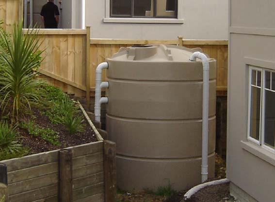
25 Stormwater Management Practice Note NSC 05: Residential Single Purpose Rain Tanks This practice note has been developed to provide general information on the minimum design and sizing requirements for single purpose rain tanks which are used in residential applications for on-site stormwater management in order to comply with District Plan Rule It is applicable to all areas of the city except the Long Bay Structure Plan Area. Refer to Stormwater management Practice Note NSC 08 for single purpose rain tanks which are used for nonresidential applications. 5.1 Introduction Single purpose rain tanks are appropriate for use in an urban environment where there is a supply of treated potable water available. They are used to collect water from your roof and store it for non-potable use on the property. The water from these tanks should be used primarily for flushing your toilet and laundry supply but can also be used for outside purposes such as garden watering and washing cars etc if desired. 5.2 Description Figure 5.1 : Single purpose rain tank Single purpose rain tanks are above or below ground tanks which are used to store rainfall collected from roof areas for non-potable use within the building. These tanks have two functions. They reduce the total volume of stormwater which runs off your site, especially from the frequent small rainfall events, and they reduce the demand for potable water from the council water supply system. Figure 5.2 is a schematic of a single purpose rain tank.
26 Stormwater Management Practice Note NSC 05 Residential Single Purpose Rain Tanks Figure 5.2 : Schematic layout of a single purpose rain tank 5.3 When should single purpose rain tanks be used? Single purpose rain tanks may be used as one of the on-site stormwater mitigation methods used to meet the permitted activity requirements of District Plan Rule 8.4.8, in Stormwater Management Areas 1, 2 and 3, when your site drains directly to an approved stormwater detention facility which has been designed to manage peak flows and provide aquatic stream protection. They are most suitable for managing roof areas over 100m 2 when new toilets and/or laundry are being installed as part of the project. They are not really suitable for roof areas of less than 50m 2 as insufficient rainwater is captured, or for small additions which do not include the installation of a toilet or laundry as retrofitting of plumbing can prove to be difficult. 5.4 Advantages of a Single Purpose Rain Tanks Single purpose rain tanks provide the following benefits: They reduce the use of potable water from the public water supply system They reduce the annual volume of water which runs off from your site They capture the first flush of runoff and thereby improve water quality 5.5 Minimum Design Requirements The rain tank must meet the following minimum design requirements: 1. Tank volume : A minimum tank size of 3,000L or 3m 3 is required. Note that this refers to the working volume of the tank between the lowest outlet and the overflow. 2. Catchment : Only roof water should be drained to the rain tank. The roof area must be drained via the rain tank should be maximised. If it is not then the allowable additional unmitigated area will be reduced by an amount equivalent to the area which is not drained 5-2
27 Stormwater Management Practice Note NSC 05 Residential Single Purpose Rain Tanks to the tank. Decks should not be drained to the tank. Rain tanks are not really suitable for small catchment areas less than 50m Offset mitigation : The allowable additional unmitigated area is 25% of the roof area drained to the rain tank. 4. Tank use : The tank must be connected via a pump to all toilets and the laundry, and may be connected to the outside taps if desired. Caution is advised when connecting to outside taps due to possible health risks. Note that if used for small additions less than 75m 2 which do not include plumbing to a toilet or laundry they may be used to supply non-potable water for outside purposes only, but will not achieve the additional 25% offset mitigation allowance. 5. Backup water supply : A backup water supply must be provided from the potable water supply for those occasions when the tank runs dry. The NSCC Rain Tank Guidelines provide a number of options for achieving this however a solenoid controlled bypass system is the preferred option. It is important for whichever option is installed that the provision is made to protect the potable water supply from cross contamination by means of an approved backflow prevention device or air-gap. 6. The tank may be above or below ground but if it is below ground then it must be clearly identifiable and contaminated water from non-roof areas must be prevented from getting into the tank, including the provision of backflow prevention methods to ensure no stormwater surcharges back into the tank.. 7. Pipes supplying non-potable water must be clearly marked by using a different lilac colour pipe. 8. All taps connected to the non-potable water source must be clearly marked as not for drinking (see symbol). These taps are generally outdoor garden taps but it also applies for indoor taps such as the laundry cold water tap. The taps should also be colour coded with either a lilac ring or lilac powder coated. 9. Access : Suitable access must be provided to the tank, the pump, and any screens or filters and the for maintenance and regular inspections. The location of these items must be clearly identified. It is advisable to provide some or all of the following: Some form of leaf guards on your gutters Insect screens A first flush diverter which diverts the most contaminated roof runoff A Tank Vac type overflow which helps to remove sediment build up from the bottom of your tank A filter at you pump 5-3
28 Stormwater Management Practice Note NSC 05 Residential Single Purpose Rain Tanks An inlet system which prevents sediment from being stirred up when the tank is nearly empty. More details on rain tank design are available in the NSCC Rain Tank Guidelines, which are available on the council website. 5.6 Maintenance Rainwater tanks need to be maintained regularly to ensure that the system is operating as it is intended and that water quality is satisfactory. Two copies of an Operation and Maintenance Manual must be provided, one copy to be held on site and the other copy to be kept on the Council property file. (Refer to the NSCC Rain Tank Guidelines for full details on maintenance recommendations). In summary maintenance requirements are: Maintenance Action Inspect and clean pre-screening devices and filters. Inspect and clean gutters and overflows. Inspect tank for sludge/sediment build up, inspect and clean gutters and clear surrounding vegetation and overhanging trees from roof areas. Backflow preventer inspected by certified inspector. Inspect tank structural integrity, pipework, electrical and pump by qualified professionals. Frequency 3 months or less 6 months or less Yearly or less 5 yearly or less 5.7 Additional Information North Shore City Council Rain Tank Guidelines, First Edition, July

29 Stormwater Management Practice Note NSC 05 Residential Single Purpose Rain Tanks Figure 5.3 : Above Ground Single Purpose Rain Tank Typical Components 5-5

30 Stormwater Management Practice Note NSC 05 Residential Single Purpose Rain Tanks Figure 5.4 : Under Ground Single Purpose Rain Tank Typical Components 5-6

31 Stormwater Management Practice Note NSC 06: Dual Purpose Rain Tanks for Residential Applications This practice note has been developed to provide general information on the minimum design and sizing requirements for dual purpose rain tanks which are used in residential applications for on-site stormwater management in order to comply with District Plan Rule It is applicable to all areas of the city except the Long Bay Structure Plan Area. Refer to Stormwater management Practice Note NSC 09 for dual purpose rain tanks which are used for nonresidential applications. 6.1 Introduction Dual purpose rain tanks are tanks which combine the benefits from both rainwater harvesting and detention into a single tank. These tanks are applicable in an urban environment where there is a public water supply available for potable use and to supplement the tank water. The harvested water from these tanks should be used primarily for toilet flushing and laundry supply but can also be used for other non-potable purposes such as garden watering and car washing, etc. Figure 6.1 : Dual Purpose Rain Tank 6.2 Description Dual purpose rain tanks are above or below ground tanks which comprises two sections, above and below a small diameter orifice part way up the side of the tank. The volume below the orifice is used to store rainfall collected from roof areas for non-potable use within the building, while the volume above the orifice is used for detention and the orifice allows the slow-release of roof run-off during and after rainfall events. These tanks serve three main functions and reduce:

32 Stormwater Management Practice Note NSC 06 Residential Dual Purpose Rain Tanks the volume of stormwater which runs off your site, especially from the frequent small rainfall events; the peak flows from less frequent larger events so that they approximate predevelopment peak flows; and the demand for potable water from the council water supply system. Figure 6.2 : Schematic layout of a Dual Purpose Rain Tank 6.3 When should dual purpose rain tanks be used? Dual purpose rain tanks may be used as one of the on-site stormwater mitigation methods used to meet the permitted activity requirements of District Plan Rule in Stormwater Management Areas 1, 2 and 3 where your site does not drain directly to an approved stormwater detention facility which has been designed to manage peak flows and provide aquatic stream protection. They are most suitable for managing roof areas over 100m 2 when new toilets and/or laundry are being installed as part of the project. They are not really suitable for roof areas of less than 50m 2 as insufficient rainwater is captured, or for small additions which do not include the installation of a toilet or laundry as retrofitting of plumbing can prove to be difficult. 6.4 Advantages of dual purpose rain tanks Dual purpose rain tanks provide the following benefits: They reduce the use of potable water from the public water supply system They reduce the annual volume of water which runs off from your site They reduce peak flows from storm events up to a 10 year event They capture the first flush of runoff and thereby improve water quality 6-2
33 Stormwater Management Practice Note NSC 06 Residential Dual Purpose Rain Tanks 6.5 Minimum Design Requirements The rain tank must meet the following minimum design requirements: 1. Tank volume : The tanks should be sized according to the roof area that can drain to the tank using Table 1 to follow the permitted activity route under District Plan Rule A minimum tank size of 4.500L (4.5m 3 ) is required. Note that this refers to the working volume of the tank between the lowest outlet and the overflow level. A minimum harvesting volume of 2m 3 is required. Table 6.1 : Dual Purpose Rain Tank Sizes (taken from District Plan, Table 8H.1) Roof Area (1) (m 2 ) Total Rain Tank Size (2) (m 3 ) Harvesting Volume (3) (m 3 ) > 400 4m 3 per 100m 2 of roof See Note (4) Notes: (1) Roof Area refers to roof area connected to the rain tank. This may be less than the total roof area. (2) Rain Tank Size means the minimum dual purpose rain tank size required to mitigate the Roof Area. It refers to the working or active volume of the tank between the lowest outlet and the overflow. (3) Harvesting Volume means the volume used to store non-potable water to supply the toilet and laundry. (4) 4.5 for a single dwelling, otherwise 3m 3 for the first dwelling unit and 2m 3 for subsequent units 2. Catchment : Only roof water should be drained to the rain tank. The roof area drained via the rain tank should be maximised. If it is not then the allowable additional unmitigated area will be reduced by an amount equivalent to the area which is not drained to the tank. Decks should not be drained to the tank. Rain tanks are not really suitable for small catchment areas less than 50m Offset mitigation : The allowable additional unmitigated area is 25% of the roof area drained to the rain tank. 4. Tank use : The tank must be connected via a pump to all toilets and the laundry, and may be connected to the outside taps if desired. Caution is advised when connecting to outside taps due to possible health risks. (Note that if used for small additions less than 75m 2 which do not include plumbing to a toilet or laundry they may be used to supply non-potable water for outside purposes only, but will not achieve the additional 25% offset mitigation allowance.) 6-3
34 Stormwater Management Practice Note NSC 06 Residential Dual Purpose Rain Tanks 5. Backup water supply : A backup water supply must be provided from the potable water supply for those occasions when the tank runs dry. The NSCC Rain Tank Guidelines provide a number of options for achieving this however a solenoid controlled bypass system is the preferred option. It is important for whichever option is installed that the provision is made to protect the potable water supply from cross contamination by means of an approved backflow prevention device or air-gap. 6. The tank may be above or below ground but if it is below ground then it must be clearly identifiable and contaminated water from non-roof areas must be prevented from getting into the tank, including the provision of backflow prevention methods to ensure no stormwater surcharges back into the tank. 7. Pipes supplying non-potable water must be clearly marked by using a different lilac colour pipe. 8. All taps connected to the non-potable water source must be clearly marked as not for drinking (see symbol). These taps are generally outdoor garden taps but it also applies for indoor taps such as the laundry cold water tap. The taps should also be colour coded with either a lilac ring or lilac powder coated. 9. Access : Suitable access must be provided to the tank, pump, the small diameter orifice and any screens or filters for maintenance and inspections. The location of these items must be clearly identified. 10. Orifice location : A small diameter orifice should be positioned part way up the tank to provide the detention part of the tank. For tanks larger than 6m 3 this should be placed at 1/3 rd of the height of the tank, while for tanks between 4.5m 3 and 6m 3 it should be placed so that 2m 3 (minimum volume) is available below the position of the orifice. The volume below the orifice is used for rainwater harvesting. 11. Size of the orifice: For maintenance reasons, the minimum size of the orifice should be 10mm in diameter. This should be used for all tanks of 6m 3 or less in volume. For larger tanks the size of the orifice is related to the volume and depth of the tank and should be designed as per the chart in Figure 6.3 below: (Note: Tank volume refers to total tank volume not just detention volume and the tank depth refers to the total tank depth) 6-4
35 Stormwater Management Practice Note NSC 06 Residential Dual Purpose Rain Tanks Residential Dual-purpose Raintanks Orifice Sizing Chart 18 Orifice Diameter (mm) Tank Depth 1.0m Deep 1.2m Deep 1.5m Deep 1.8m Deep 2.1m Deep 2.4m Deep 2.7m Deep 3.0m Deep Use Total Tank Depth (m) Total Tank Volume (m 3 ) Figure 6.3 : Orifice Sizing Chart It is advisable to provide some or all of the following: Some form of leaf guards on your gutters Insect screens A first flush diverter which diverts the most contaminated roof runoff A Tank Vac type overflow which helps to remove sediment build-up from the bottom of your tank A filter at you pump An inlet system which prevents sediment from being stirred up when the tank is nearly empty. 6.6 Maintenance Rainwater tanks need to be maintained regularly to ensure that the system is operating as it is intended and that water quality is satisfactory. Two copies of an Operation and Maintenance Manual must be provided, one copy to be held on site and the other copy to be kept on the Council property file. (Refer the NSCC Rain Tank Guidelines for full details on maintenance recommendations). 6-5
36 Stormwater Management Practice Note NSC 06 Residential Dual Purpose Rain Tanks In summary maintenance requirements are: Maintenance Action Inspect and clean pre-screening devices and filters. Inspect and clean gutters, overflows and small diameter orifice. Inspect tank for sludge/sediment build up, inspect and clean gutters and clear surrounding vegetation and overhanging trees from roof areas. Backflow preventer inspected by certified inspector. Inspect tank structural integrity, pipework, electrical and pump by qualified professionals. Frequency 3 months or less 6 months or less Yearly or less 5 yearly or less 6.7 Additional Information North Shore City Council Rain Tank Guidelines, First Edition, July 2008 Figure 6.4 : Above Ground Dual Purpose Rain Tank Typical Components 6-6
37 Stormwater Management Practice Note NSC 06 Residential Dual Purpose Rain Tanks Figure 6.5 : Below Ground Dual Purpose Rain Tank Typical Components 6-7


38 Stormwater Management Practice Note NSC 07: Detention Tanks This practice note has been developed to give general information on the minimum design requirements and maintenance of detention tanks for both residential and non-residential applications for on-site stormwater management in order to comply with District Plan Rule It is applicable to all areas of the city except the Long Bay Structure Plan Area. 7.1 Introduction Detention tanks are tanks which temporarily store rain water from your roof and other hard surfaces and release it at a slower rate so that the peak flows are no more than they were before the development took place. These tanks are applicable in an urban environment where there is a lack of capacity in the downstream stormwater system, where flooding of other properties is a problem, and where extended high flows are unlikely to increase stream erosion. Figure 7.1 : Detention Tank 7.2 Description Detention tanks work by temporarily storing the rainwater runoff during a rainfall event and then slowly releasing the water through a controlled small diameter orifice into the public stormwater system. This storage and slow release of the rainwater reduces the peak stormwater flows during a rainfall event and hence reduces the impacts on downstream infrastructure and/or streams.

39 Stormwater Management Practice Note NSC 07 Detention tanks Figure 7.2 : Schematic layout of a detention tank The tank size can vary anywhere from 1m 3 upwards depending on the required stormwater controls. They can be above or below ground. Run-off from roof surfaces and paved areas can both be collected by the tank. 7.3 When should detention tanks be used? Detention tanks may be used as one of the on-site stormwater mitigation methods used to meet the permitted activity requirements of District Plan Rule in Stormwater Management Area Advantages of detention tanks Detention tanks provide the following benefits: They capture the first flush of runoff and thereby improve water quality They reduce peak flows from rainfall events up to a 10 year event They can be used for managing peak flows from both roof areas and paved areas 7.5 Minimum Design Requirements 1. Tank volume : The tank size will depend on the area that requires mitigation and the proportion of the impervious area that is able to be drained via the tank. To manage peak flows from a 10% (10 Yr) and 50% (2 yr) AEP rainfall events you require approximately 3m 3 of storage for every 100m 2 of catchment area. The required size can be read off using the solid line on Figure 7.3 below. It is possible for a tank to provide mitigation for some area (up to 25%) that does not drain to it. This is called offset mitigation. It this case the tank needs to be slightly larger and the orifice slightly smaller to compensate for the area not draining to the tank. You 7-2
40 Stormwater Management Practice Note NSC 07 Detention tanks can read off the required size using the dashed line on Figure 7.3. In this situation the Contributing Impermeable Area refers to the total area that is being mitigated. Note that the design volume refers to the useable storage volume between the centre of the outlet orifice and the overflow level and that a minimum tank size has been set at 1m 3. Detention Tank Selection Chart Detention Tank Volume (m 3 ) % - 95% of Area Connected to Tank > 95% of Area Connected to Tank Contributing Impermeable Area (m 2 ) Figure 7.3 : Detention Tank Selection Chart 2. Overflow : An overflow must be provided which drains to an approved stormwater outfall. The overflow must be sized so that it is at least the same size as the inlet to the tank. 3. Access : Access must be provided for maintenance. Especially the orifice which must be accessible when the tank is full. 4. Inlets from paved areas require catchpit inserts as sediment traps. 5. Tanks may be above or below ground but must be clearly identifiable for maintenance and inspection purposes. Below ground tanks must be located so as not to adversely affect building foundations. 6. Position of the orifice : A dead storage volume is required at bottom of the tank for sediment build up the orifice is to be located at least 100mm above the base of the tank and must be located so that it can easily be accessed for inspection and maintenance. 7. Size of the orifice for 2 & 10 yr : The size of the orifice is dependant on the type of detention to be provided as well as the volume and depth of the tank. Figures 7.5 and 7.6 below can be used as a first approximation to size the orifice. For maintenance reasons, the minimum size of the orifice should be 10mm in diameter. Fore more detail refer to the NSCC Rain Tank Guidelines. 7-3
41 Stormwater Management Practice Note NSC 07 Detention tanks Detention Tank Orifice Selection Chart (>95% of Area Connected to Tank) Orifice Diameter (mm) Tank Depth 0.5m Deep 1.0m Deep 1.5m Deep 2.0m Deep 2.5m Deep 3.0m Deep Use Depth to Orifice (m) Tank Volume (m 3 ) Figure 7.5: Orifice Sizing Chart for 2yr & 10yr Detention Detention Tank Orifice Selection Chart (75% - 95% of Area Connected to Tank) Orifice Diameter (mm) Tank Depth 0.5m Deep 1.0 m Deep 1.5m Deep 2.0m Deep 2.5m Deep 3.0m Deep Use Depth to Orifice (m) Tank Volume (m 3 ) Figure 7.6: Orifice Sizing Chart for 2yr & 10yr Detention 7-4

42 Stormwater Management Practice Note NSC 07 Detention tanks 7.5 Maintenance Rainwater tanks need to be maintained regularly to ensure that the system is operating as it is intended and that water quality is satisfactory. Two copies of an Operation and Maintenance Manual must be provided, one copy to be held on site and the other copy to be kept on the Council property file. (Refer the NSCC Rain Tank Guidelines for full details on maintenance). In summary maintenance requirements are: Maintenance Action Inspect and clean pre-screening devices and filters. Inspect and clean gutters and overflows. Inspect tank for sludge/sediment build up, inspect and clean gutters and clear surrounding vegetation and overhanging trees from roof areas. Inspect tank structural integrity and pipework by qualified professionals Frequency 3 months or less 6 months or less Yearly or less 5 yearly or less 7.6 Additional Information North Shore City Council Rain Tank Guidelines, First Edition, July 2008 Figure 7.7: Below Ground Detention Tank Typical Components 7-5
43 Stormwater Management Practice Note NSC 07 Detention tanks Figure 7.8: Above Ground Detention Tank Typical Components 7-6

44 Stormwater Management Practice Note NSC 08: Single Purpose Rain Tanks for Non-Residential Applications This practice note has been developed to provide general information on the minimum design and sizing requirements for single purpose rain tanks which are used in non-residential applications in all parts of the city other than the Long Bay Structure Plan Area. These rain tanks are used to collect water from your roof and store it for non-potable toilet use on the property. 8.1 Introduction Single purpose rain tanks are applicable in an urban environment where there is a supply of treated potable water available. North Shore City Council has set a minimum size of 3,000 litres or 3m 3 for these tanks. The water from these tanks should be used primarily for flushing your toilet but can also be used for outside purposes such as garden watering and washing cars etc if desired. 8.2 Description Figure 8.1 : Commercial Single Purpose Rain Tank These tanks have two functions. They reduce the total volume of stormwater which runs off your site, especially from the frequent small rainfall events, and they reduce the demand for potable water from the council water supply system. Figure 2 is a schematic of a single purpose rain tank. More details on rain tank design are available in the NSCC Rain Tank Guidelines, which are available on the council website.
45 Stormwater Management Practice Note NSC 08 Single Purpose Rain Tanks for Non-Residential Applications - Figure 8.2 : Schematic layout of a commercial single purpose rain tank 8.3 When should single purpose rain tanks be used? Single purpose rain tanks may be used as one of the on-site stormwater mitigation methods used to meet the permitted activity requirements of District Plan Rule in Stormwater Management Areas 1, 2 and 3 when your site drains directly to an approved stormwater detention facility which has been designed to manage peak flows and provide aquatic stream protection. They are most suitable for managing roof areas over 100m 2 when new toilets and/or laundry are being installed as part of the project. They are not really suitable for roof areas of less than 50m 2 as insufficient rainwater is captured, or for small additions which do not include the installation of a toilet or laundry as retrofitting of plumbing can prove to be difficult. For business developments with only 1 toilet harvesting is not required due to low potential water use. 8.4 Advantages of a Single Purpose Rain Tanks Single purpose rain tanks provide the following benefits: They reduce the use of potable water from the public water supply system which is more sustainable They reduce the annual volume of water which runs off from your site which helps to protect our streams They capture the first flush of runoff and thereby improve water quality 8.5 Minimum Design Requirements The rain tank must meet the following minimum design requirements: 1. Tank Size : The size of the tank should be based on roof area and expected water use and calculated using the procedure set out in section 8.6 below. A minimum tank size of 8-2
46 Stormwater Management Practice Note NSC 08 Single Purpose Rain Tanks for Non-Residential Applications - 3,000L or 3m 3 is required. Note that this refers to the working volume of the tank between the lowest outlet and the overflow. 2. Catchment : Only roof water should be drained to the rain tank. The roof area must be drained via the rain tank should be maximised. If it is not then the allowable additional unmitigated area will be reduced by an amount equivalent to the area which is not drained to the tank. Decks should not be drained to the tank. 3. Tank use : The tank must be connected via a pump to all toilets and may be connected to the outside taps if desired. Caution is advised when connecting to outside taps due to possible health risks. 4. Back-up water supply : A backup water supply must be provided from the potable water supply for those occasions when the tank runs dry. The NSCC Rain Tank Guidelines provide a number of options for achieving this however a solenoid controlled bypass system is the preferred option. It is important for whichever option is installed that the provision is made to protect the potable water supply from cross contamination by means of an approved backflow prevention device or air-gap. 5. The tank may be above or below ground but if it is below ground then it must be clearly identifiable and contaminated water from non-roof areas must be prevented from getting into the tank, including the provision of backflow prevention methods to ensure no stormwater surcharges back into the tank.. 6. Pipes supplying non-potable water must be clearly marked by using a different lilac colour pipe. 7. All taps connected to the non-potable water source must be clearly marked as not for drinking (see symbol). These taps are generally outdoor garden taps. The taps should also be colour coded with either a lilac ring or lilac powder coated. 8. Access : Proper access must be provided to the tank, any screens or filters and the pump for maintenance and regular inspections. The location of these items must be clearly identified. It is advisable to provide some or all of the following: Some form of leaf guards on your gutters Insect screens A first flush diverter which diverts the most contaminated roof runoff A Tank Vac type overflow which helps to remove sediment build up from the bottom of your tank A filter at you pump An inlet system which prevents sediment from being stirred up when the tank is nearly empty. 8-3
47 Stormwater Management Practice Note NSC 08 Single Purpose Rain Tanks for Non-Residential Applications Procedure for calculating rainwater harvesting volume This is may be used for non-residential or mixed use developments where the building has more than one toilet. It refers to the working volume of the tank between the lowest takeoff and the overflow level which shall be the larger of 3m 3 or the volume determined using the methodology below. The methodology uses the following basic steps: (A simple worksheet is provided at the back of this practice note). Step 1: Determine Gross Floor Area Determine the gross floor area (GFA) for each of the activities that the building is to be used for. This should have already have been determined when establishing parking requirements etc. Use activities provided in Table 3 below. If the activity is not listed then use the one that is the most similar. Step 2: Determine Building Occupancy The average building occupancy (BO) is an estimate of the number of people likely to use the building based on gross floor area. The following table should be used to calculate the probable number of occupants in a building based on gross floor area. If the activity is not provided then use the most similar activity provided in the table. Table 8.1 : Building Occupancy Ratios for Different Activities Activity Floor area to occupant ratio (OR) Office 25m 2 Showroom 35m 2 Warehouse 50m 2 Shops, retail 35m 2 Restaurant/Dining areas 15m 2 Local shopping centres 35m 2 Manufacturing industry 25m 2 Residential component of mixed use 20m 2 Determine building occupancy number (BO) for the building by dividing the gross floor area (GFA) for each activity by the floor area to occupant ratio (OR) for that activity. Add up the total number of people that will be in the building. Step 3: Determine Roof Area that will be connected to the Rain Tank RA = roof area connected to the rain tank in m 2. Note that it may be advantageous to maximise the roof area that is connected to the rain tank as the as this increases the capture of rainwater 8-4
48 Stormwater Management Practice Note NSC 08 Single Purpose Rain Tanks for Non-Residential Applications - and also may increase the additional area managed by the rain tank which is calculated in Stormwater Practice Note NSC 03. Step 4: Determine the Roof Area per Occupant The Roof area per occupant is calculated by dividing the roof area that will be connected to the rain tank (RA), by the building occupancy (BO). Roof Area per Occupant (RAO) = RA/BO Step 5: Determine the Rain Tank Harvesting Volume (Vol m 3 ) The harvesting volume that needs to be provided in the rain tank is calculated by multiplying the building occupancy calculated in Step 2 by the Rain Tank Harvesting Ratio (HR) obtained from Table 8.2. Table 8.2 : Rain Tank Harvesting Ratio Roof Area per Occupant (RAO) Rain Tank Harvesting Ratio (HR) Less than 15 m 2 of roof per occupant 0.2 m 3 per occupant m 2 of roof per occupant 0.15 m 3 per occupant m 2 of roof per occupant m 3 per occupant Greater than 40m 2 of roof per occupant 0.1 m 3 per occupant Rain Tank Harvesting Vol (m 3 ) = BO x HR This volume will be used later in determining the appropriate on-site mitigation requirements. 8.7 Maintenance Rainwater tanks need to be maintained regularly to ensure that the system is operating as it is intended and that water quality is satisfactory. Two copies of an Operation and Maintenance Manual must be provided, one copy to be held on site and the other copy to be kept on the Council property file. (Refer to the NSCC Rain Tank Guidelines for full details on maintenance recommendations). 8-5
49 Stormwater Management Practice Note NSC 08 Single Purpose Rain Tanks for Non-Residential Applications - In summary maintenance requirements are: Maintenance Action Inspect and clean pre-screening devices and filters. Inspect and clean gutters and overflows. Inspect tank for sludge/sediment build up, inspect and clean gutters and clear surrounding vegetation and overhanging trees from roof areas. Backflow preventer inspected by certified inspector. Inspect tank structural integrity, pipework, electrical and pump by qualified professionals. Frequency 3 months or less 6 months or less Yearly or less 5 yearly or less 8.8 Additional Information North Shore City Council Rain Tank Guidelines, First Edition, July 2008 Figure 8.3 : Above Ground Single Purpose Rain Tank Typical Components 8-6

50 Stormwater Management Practice Note NSC 08 Single Purpose Rain Tanks for Non-Residential Applications - Figure 8.4 : Under Ground Single Purpose Rain Tank Typical Components 8-7

51 Stormwater Management Practice Note NSC 09: Dual Purpose Rain Tanks for Non-Residential Applications This practice note has been developed to provide general information on the minimum design and sizing requirements for dual purpose rain tanks which are used in non-residential applications for on-site stormwater management in order to comply with District Plan Rule It is applicable to all areas of the city except the Long Bay Structure Plan Area. Refer to Stormwater Management Practice Note NSC 06 for dual purpose rain tanks which are used for residential applications. 9.1 Introduction Dual purpose rain tanks are tanks which combine the benefits from both rainwater harvesting and detention into a single tank. They are appropriate for use in an urban environment where there is a supply of treated potable water available. They are used to collect water from your roof and store it for non-potable use and provide storage for peak flow attenuation on the property. The water from these tanks should be used primarily for flushing your toilet but can also be used for outside purposes such as garden watering and washing cars etc if desired. 9.2 Description Figure 9.1 : Commercial Dual Purpose Rain Tank Dual purpose rain tanks are above or below ground tanks which are used to slow down runoff from your site and store rainfall collected from roof areas for non-potable use within the building. The tank comprises two sections, above and below a small diameter orifice part way up the side of the tank. The volume below the orifice is used primarily for rainwater harvesting purposes (for non-potable water uses), while the volume above the orifice is used for detention and the orifice allows the slow-release of roof run-off during and after rainfall events.
52 Stormwater Management Practice Note NSC 09 Dual-purpose Rain Tanks for Non-Residential Applications - These tanks have three functions and reduce: the volume of stormwater which runs off your site, especially from the frequent small rainfall events; peak flows from less frequent larger events so that they approximate pre-development peak flows; and demand for potable water from the council water supply system. Figure 9.2 : Schematic layout of a commercial dual purpose rain tank 9.3 When should dual purpose rain tanks be used? Dual purpose rain tanks may be used for roof areas greater than 50m 2 as one of the on-site stormwater mitigation methods used to follow a permitted activity requirements of District Plan Rule in Stormwater Management Areas 1, 2 and 3 when your site does not drain directly to an approved stormwater detention facility which has been designed to manage peak flows and provide aquatic stream protection. They are most suitable for managing roof areas over 100m 2 when new toilets and/or laundry are being installed as part of the project. They are not really suitable for roof areas of less than 50m 2 as insufficient rainwater is captured, or for small additions which do not include the installation of a toilet or laundry as retrofitting of plumbing can prove to be difficult. For business developments with only 1 toilet harvesting is not required due to low potential water use. 9.4 Advantages of dual purpose rain tanks Dual purpose rain tanks provide the following benefits: They reduce the use of potable water from the public water supply system which is more sustainable 9-2
53 Stormwater Management Practice Note NSC 09 Dual-purpose Rain Tanks for Non-Residential Applications - They reduce the annual volume of water which runs off from your site and this helps to protect our streams They reduce peak flows from storm events up to a 10 year event which reduces downstream flooding They capture the first flush of runoff and thereby improve water quality 9.5 Minimum Design Requirements The rain tank must meet the following minimum design requirements: 1. Rain tank volume requirements : The total working volume of the rain tank between the lowest takeoff and the overflow level is required to store 4m 3 per 100m 2 of roof area connected to the rain tank. The tank comprises two sections, above and below a small diameter orifice part way up the side of the tank. The section above the orifice provides detention while the section below the orifice is used to store water for harvesting. The location of the orifice is dependant on the volume required for harvesting which is discussed below. The volume required for harvesting should be based on roof area and expected water use and calculated using the procedure set out in section 9.6 below. A minimum tank size of 4.500L (4.5m 3 ) is required. Note that this refers to the working volume of the tank between the lowest outlet and the overflow level. A minimum volume of 2m 3 is required for rainwater harvesting. 2. Catchment : Only roof water should be drained to the rain tank. The roof area drained via the rain tank should be maximised. If it is not then the allowable additional unmitigated area will be reduced by an amount equivalent to the area which is not drained to the tank. Decks should not be drained to the tank. Rain tanks are not suitable for roof areas of less than 50m Tank use : The tank must be connected via a pump to all toilets, and may be connected to the outside taps if desired. Caution is advised when connecting to outside taps due to possible health risks. 4. Backup water supply : A backup water supply must be provided from the potable water supply for those occasions when the tank runs dry. The NSCC Rain Tank Guidelines provide a number of options for achieving this however a solenoid controlled bypass system is the preferred option. It is important for whichever option is installed that the provision is made to protect the potable water supply from cross contamination by means of an approved backflow prevention device or air-gap. 5. The tank may be above or below ground but if it is below ground then it must be clearly identifiable and contaminated water from non-roof areas must be prevented from getting into the tank, including the provision of backflow prevention methods to ensure no stormwater surcharges back into the tank. 6. Pipes supplying non-potable water must be clearly marked by using a different lilac colour pipe. 9-3
. These taps are generally outdoor garden taps.")
54 Stormwater Management Practice Note NSC 09 Dual-purpose Rain Tanks for Non-Residential Applications - 7. All taps connected to the non-potable water source must be clearly marked as not for drinking (see symbol). These taps are generally outdoor garden taps. The taps should also be colour coded with either a lilac ring or lilac powder coated. 8. Access : Proper access must be provided to the tank, the small diameter orifice, any screens or filters and the pump for maintenance and regular inspections. The location of these items must be clearly identified. 9. Position of the orifice : A small orifice is required part way up the tank to provide the detention part of the tank. The location of the orifice will depend on the volume of water that is required for harvesting. It should be placed so that at least 2m 3 (minimum volume) is available below the position of the orifice. The volume below the orifice is used for rainwater harvesting. 10. Size of the orifice : For maintenance reasons, the minimum size of the orifice should be 10mm in diameter. This should be used for all tanks of 6m 3 or less in volume. For larger tanks the size of the orifice is related to the volume and depth of the tank and should be designed as per Figure 9.3 below: (Note: Use the total tank volume and depth to the orifice in this figure) Business Dual-purpose Raintanks Orifice Sizing Chart 40 Orifice Diameter (mm) Tank Depth 0.6m Deep 0.8m Deep 1.0m Deep 1.2m Deep 1.4m Deep 1.6m Deep 1.8m Deep 2.0m Deep Use Depth to Orifice (m) Total Tank Volume (m 3 ) Figure 9.3 : Orifice Sizing Chart It is advisable to provide some or all of the following: Some form of leaf guards on your gutters Insect screens 9-4
55 Stormwater Management Practice Note NSC 09 Dual-purpose Rain Tanks for Non-Residential Applications - A first flush diverter which diverts the most contaminated roof runoff A Tank Vac type overflow which helps to remove sediment buildup from the bottom of your tank A filter at you pump An inlet system which prevents sediment from being stirred up when the tank is nearly empty. More details on rain tank design are available in the NSCC Rain Tank Guidelines, which are available on the council website. 9.6 Procedure for calculating rainwater harvesting volume This may be used for non-residential or mixed use developments where the building has more than one toilet. It refers to the working volume of the tank between the lowest takeoff and the orifice level which shall be the larger of 2m 3 or the volume determined using the methodology below. The methodology uses the following basic steps: (A simple worksheet is provided at the back of this practice note). Step 1: Determine Gross Floor Area Determine the gross floor area (GFA) for each of the activities that the building is to be used for. This should have already have been determined when establishing parking requirements etc. Use activities provided in Table 1 below. If the activity is not listed then use the one that is the most similar. Step 2: Determine Building Occupancy The average building occupancy (BO) is an estimate of the number of people likely to use the building based on gross floor area. The following table should be used to calculate the probable number of occupants in a building based on gross floor area. If the activity is not provided then use the most similar activity provided in the table. Table 9.1 : Building Occupancy Ratios for Different Activities Activity Floor area to occupant ratio (OR) Office 25m 2 Showroom 35m 2 Warehouse 50m 2 Shops, retail 35m 2 Restaurant/Dining areas 15m 2 Local shopping centres 35m 2 Manufacturing industry 25m 2 Residential component of mixed use 20m 2 9-5
56 Stormwater Management Practice Note NSC 09 Dual-purpose Rain Tanks for Non-Residential Applications - Determine building occupancy number (BO) for the building by dividing the gross floor area (GFA) for each activity by the floor area to occupant ratio (OR) for that activity. Add up the total number of people that will be in the building. Step 3: Determine Roof Area that will be connected to the Rain Tank RA = roof area connected to the rain tank in m 2. Note that it may be advantageous to maximise the roof area that is connected to the rain tank as the as this increases the capture of rainwater and also may increase the additional area managed by the rain tank which is calculated in Stormwater Practice Note NSC 03. Step 4: Determine the Roof Area per Occupant The Roof area per occupant is calculated by dividing the roof area that will be connected to the rain tank (RA), by the building occupancy (BO). Roof Area per Occupant (RAO) = RA/BO Step 5: Determine the Rain Tank Harvesting Volume (Vol m 3 ) The harvesting volume that needs to be provided in the rain tank is calculated by multiplying the building occupancy calculated in Step 2 by the Rain Tank Harvesting Ratio (HR) obtained from Table 9.2. Table 9.2 : Rain Tank Harvesting Ratio Roof Area per Occupant (RAO) Rain Tank Harvesting Ratio (HR) Less than 15 m 2 of roof per occupant 0.2 m 3 per occupant m 2 of roof per occupant 0.15 m 3 per occupant m 2 of roof per occupant m 3 per occupant Greater than 40m 2 of roof per occupant 0.1 m 3 per occupant Rain Tank Harvesting Vol (m 3 ) = BO x HR This volume will be used later in determining the appropriate on-site mitigation requirements. 9.7 Maintenance Rainwater tanks need to be maintained regularly to ensure that the system is operating as it is intended and that water quality is satisfactory. Two copies of an Operation and Maintenance Manual must be provided, one copy to be held on site and the other copy to be kept on the Council property file. (Refer the NSCC Rain Tank Guidelines for full details on maintenance recommendations). 9-6

57 Stormwater Management Practice Note NSC 09 Dual-purpose Rain Tanks for Non-Residential Applications - In summary maintenance requirements are: Maintenance Action Inspect and clean pre-screening devices and filters. Inspect and clean gutters, overflows and small diameter orifice. Inspect tank for sludge/sediment build up, inspect and clean gutters and clear surrounding vegetation and overhanging trees from roof areas. Backflow preventer inspected by certified inspector. Inspect tank structural integrity, pipework, electrical and pump by qualified professionals. Frequency 3 months or less 6 months or less Yearly or less 5 yearly or less 9.8 Additional Information North Shore City Council Rain Tank Guidelines, First Edition, July 2008 Figure 9.4 : Above Ground Dual Purpose Rain Tank Typical Components 9-7
58 Stormwater Management Practice Note NSC 09 Dual-purpose Rain Tanks for Non-Residential Applications - Figure 9.5 : Below Ground Dual Purpose Rain Tank Typical Components 9-8


59 Stormwater Management Practice Note NSC 10: Bio-Retention This practice note has been developed to provide guidance in meeting the minimum requirements in the District Plan Rule for the use of bio-retention for on-site stormwater management. It is applicable to all areas of the city except the Long Bay Structure Plan Area Introduction Bio-retention systems are shallow, planted areas which filter stormwater runoff through a vegetated soil media layer. It is a concept that was developed by Prince Georges County, Maryland in the United States in the early 1990 s and is now widely accepted as one of the best stormwater management practices. It makes uses of the chemical, biological and physical properties of plants, microbes and soils and is an effort to mimic nature Description Figure 10.1 : Award winning rain garden (Ellerslie Flower Show 2007) Bio-retention in the North Shore City context encompasses a number of different devices: rain gardens, bio-retention swales, stormwater planters and tree pits. Green roofs are similar to bioretention but are dealt with separately in Practice Note NSC 12. North Shore City Council has a bioretention guidelines manual available on the council web site. A rain garden is essentially a sunken garden with good well drained soil and an underdrain to which stormwater is directed. Figure 10.2 : Typical Rain garden


60 Stormwater Management Practice Note NSC 10 Bio-Retention A bio-retention swale is a long narrow sloping swale with a bio-retention system along the base of the swale. It can be used to convey as well as treat stormwater. Figure 10.3 : Bio-retention swale A stormwater planter is an above ground garden in a large container with bio-retention soil media and an underdrain to which stormwater is directed. Figure 10.4 : Stormwater planter Tree pits which are used for planting of street trees can also be used for bio-retention as long as they are designed with an appropriate underdrain system. Figure 10.5 : Tree-pit 10-2
61 Stormwater Management Practice Note NSC 10 Bio-Retention 10.3 When are Bio-Retention Devices Required? Bio-retention devices may be used to meet the permitted activity standards for on-site stormwater mitigation required by district plan Rule Under this rule the following bioretention sizes are required for managing stormwater runoff from residential and non-residential impervious areas: Where the site does not drain directly to an approved stormwater detention facility, 8m 2 of bio-retention area per 100m 2 of impervious area to capture, hold and release in a controlled manner. Where the site does drain directly to an approved stormwater detention facility, 5m 2 of bio-retention area per 100m 2 of impervious area. (Note that an approved detention facility refers to a stormwater device which has been designed to accommodate the proposed development on your site and provides adequate stormwater mitigation for the 2 and 10 year rainfall events as well as providing extended detention for stream protection) Refer to the following stormwater management practice notes to determine if or when a bioretention is required: NSC 03 Permitted Activity Route NSC 04 Controlled Activity Route 10.4 Advantages of a Bio-Retention Device Bio-retention offers a number of benefits which is why it is one of the preferred methods for onsite stormwater mitigation. The benefits include: Improved water quality by filtering out contaminants Improved hydrological response of stormwater peak flow and volume, especially for smaller rainfall events Providing amenity and increased vegetative cover Utilises the same space as is normally used for gardens Providing better growing conditions (free draining soils) for plants and thus improves the garden Mimics nature and uses natural processes 10.5 Minimum Design Requirements A bio-retention device must meet the following minimum design requirements to qualify for the permitted or controlled activity routes through the resource consent process as required under section of the district plan. 10-3

62 Stormwater Management Practice Note NSC 10 Bio-Retention The bio-retention area comprises the following typical layers: Figure 10.6 : Typical bio-retention layers 1. Size and Shape: The bio-retention device can be any shape. Shapes that blend in with the site are more pleasing on the eye and look more natural. The bio-retention device size refers to the area that is filled with planting soil mix and should be sized so that it has an area equivalent to 8% of the impermeable area draining to it, and may be reduced to 5% if it drains to an NSCC approved stormwater pond. The minimum size for a bio-retention device is 2m 2. Note that if the calculated size for bioretention is less than 1m 2 then no device is required, if it is between 1m 2 and 2m 2 then a 2m 2 device is required. Refer to Stormwater Management Practice Note NSC 03 for sizing requirements on your site. 2. Location : Devices should be located so that stormwater can flow to the device under gravity and setback a minimum of 1m from property boundaries. Care should also be taken to avoid underground services. Devices should be at least 3m from building foundations or else a specific design and impermeable liner will be required. A stormwater planter is suited for these situations. Devices should be set back from existing retaining walls a distance equal to the height of the wall. Remember that plants need light to grow and you need access for maintenance. In areas with a slope of greater than 1:5 or geotechnically unstable areas an impermeable liner is required. 3. Inlet Design : Good inlet design is essential for a bio-retention device to work. The most important thing to consider is that the water must be able to flow into the device. (Water flows down-hill!) Flow should be directed into the device in a sheet flow over a vegetated filter strip if possible, and should always flow into the device in a manner which avoids concentrated flows and scour. If possible high flows should bypass the device. 10-4
63 Stormwater Management Practice Note NSC 10 Bio-Retention 4. Planting Soil Mix : The main component of the bio-retention device is the planting soil mix. This must be from an NSCC approved commercial source. The minimum soil depth is 600mm (500mm of planting soil mix and 100mm transition layer) which should be increased to at least 1m when trees are planted. For rain gardens, stormwater planters and tree pits the surface of the planting soil should be flat and level to avoid localised ponding and blinding, while for bio-retention swales the surface should be gently sloping. Soil compaction should be avoided, allowing natural compaction only. Install materials in 300mm layers and soak with water to aid natural compaction. Depending on the soil material, up to 20% natural compaction may occur over time. 5. Plants : Native plants are preferable but not essential. Any plants which suit your garden may be used. The plants should be able to tolerate short periods of inundation and longer dry periods, be perennial rather than annual, have deep fibrous root systems and have spreading rather than clumped growth forms. Note that the use of wetland plants is not recommended as these plants are not well suited to free draining soils. Why native plants? These are best adapted to local climate, and attract and provide habitat and food for local wildlife including birds and insects. 6. Mulch : mm surface mulch layer. Note that the depth of mulch should be taken into account when setting the overflow level. 7. Under Drain : All bio-retention devices require under drains in North Shore City due to the clay soils that occur. The under drain should be a perforated PVC pipe with a minimum diameter of 100mm and should have a minimum slope of 0.5% (5cm over 10m). For bio-retention areas up to 10m 2 a single 100mm diameter pipe will suffice, for areas between 10m 2 and 20m 2 a single 150mm or two 100mm diameter pipes will suffice. For areas larger than 20m 2 a site specific design is required. Under drain spacing - there should be one under drain per 3m width of bio-retention device. Under drains should be evenly spaced along the length of the device. They should be placed 75 to 300mm above the bottom of the drainage layer where no liner is present (Top figure below) to allow for infiltration into the in-situ soils, or on top of the liner if one is used (Bottom figure). There should be at least 25mm of drainage layer above the top of the under drain. Figure 10.7 : Location of underdrain (top without liner) (bottom with a liner) 10-5
64 Stormwater Management Practice Note NSC 10 Bio-Retention 8. Liner : An impervious liner is required when bio-retention is used in geotechnically unstable or steep sites greater than 1V:5H. The use of stormwater planters should be considered in these situations. 9. Geofabric : The use of geofabric in the construction of bio-retention devices is generally not recommended. 10. Root Barrier : The use of a root barrier should be considered when there are susceptible services such (as sewers), or foundations which are likely to be at risk from root penetration. The root barrier should only be placed adjacent to the services which require protection and not around the whole device. 11. Filter Layer : A filter layer is required between the planting soil and the drainage layer. A geofabric is not recommended for this purpose. The filter zone should consist of 50mm of pea-gravel (US #8 (1.18mm - 9.5mm) with 50mm of washed sand (0.5mm 1mm) on top of it. 12. Ponding Depth : Ponding should normally be designed for a depth of 200mm above the bed of the device. 13. Overflow : Ideally high flows should be by-passed to an overflow located outside the rain garden. If an overflow is located within the overflow can be by means of a pipe/manhole which connects into the underdrain system, or it could be a gravel curtain which connects into the drainage layer. 14. Access: Suitable access needs to be provided for routine maintenance. For small residential gardens may require access for a wheel barrow, while larger commercial gardens will require more substantial access, suitable for a small excavator Construction Ideally bio-retention devices must not be built until the rest of the site has been constructed and the site stabilised. They must be protected from stormwater flows carrying high sediment loads during construction activities from your site or neighbouring sites. If they are not protected then the planting soil mix will need to be replaced. If work on the bio-retention device needs to commence before the rest of the site is stabilised then the device should be constructed, but not planted, and covered with a geofabric and topsoil. This will later be removed and the device planted once the rest of the site has stabilised Maintenance One of the important considerations with bio-retention devices is long-term maintenance. Remember that a bio-retention device is a garden and not just a drainage system they are generally low maintenance, not NO maintenance. 10-6
65 Stormwater Management Practice Note NSC 10 Bio-Retention They need water when it doesn t rain until the plants are established. During dry periods the under drain in the bio-retention devices may cause the planting soil to dry out. Watering the vegetation on an as needed basis helps ensure a healthy condition and appearance. Mulch annually with hardwood mulch as this suppresses weeds and retains moisture. Every few years excess mulch may need to be removed. Weed regularly as you would with any garden. Don t park or drive on the device as this causes compaction and leaves ruts. Don t let (fine) sediment build up if a crust forms remove it & rework the top layer of soil. Keep an eye on the plants if they are unhappy they may need moving. Plants may need pruning, thinning or replacing from time to time. Strong water flows may cause erosion, this will need to be repaired and measures put in place to prevent recurrence. Check the overflow for clogging and remove any build up of rubbish or debris regularly Additional Information North Shore City Council Bio-retention Guidelines, First Edition, July


66 Stormwater Management Practice Note NSC 11: Pervious Paving This practice note has been developed to provide guidance in meeting the minimum requirements in the District Plan Rule for the use of pervious paving for on-site stormwater management. It is applicable to all areas of the city except the Long Bay Structure Plan Area Introduction Pervious (or permeable) paving is used to manage both water quantity and quality. When properly constructed and maintained, permeable paving is a versatile stormwater management device that can be used to treat or replace impervious surfaces. Figure 11.1 : Typical driveway and minor parking lot constructed in pervious paving Description Pervious Paving means a pavement consisting of a layered construction to enable rainwater filtration to an underdrain connected to an approved stormwater outlet, which provides a pervious surface layer specifically designed to infiltrate rainfall events up to the 10% AEP. Pervious paving consists of a permeable wearing surface that is bedded in a sand/fine gravel, laid over a gravel basecourse. A number of different surfaces are commonly used for pervious pavements. These include: Interlocking concrete block paving with permeable gaps between the pavers Interlocking permeable concrete block paving Concrete grid pavers such as Gobi Blocks Pervious concrete Pervious asphalt Reinforced gravel or turf (Plastic grid pavers)

67 Stormwater Management Practice Note NSC 11 Pervious Paving Figure 11.2 : Typical layers in a pervious pavement Infiltrated stormwater is slowed down, temporarily stored and slowly released by the basecourse, resulting in attenuation of the flow peaks. Stormwater passing through a permeable system receives treatment due to settling, filtration, absorption and microbiological action taking place in the bedding sand and basecourse. In geotechnically unstable areas, pervious paving needs an impermeable liner underlying the basecourse to prevent the infiltration of water into the adjoining soil. If a liner is necessary, it needs to be protected from puncturing by the use of a heavy-duty geotextile above the liner. This practice note applies to: Porous blocks (where the pavers are permeable) and Porous gaps (where pavers are not permeable and the infiltration takes place through the gaps or joints between the pavers). Reinforced turf or concrete grid pavers which have Private driveways and parking areas. Roads and/or heavy trafficked areas need specific design. Areas less than 250m 2 of pervious paving area. While this practice note is still relevant to larger area of pervious paving, specific design is recommended to limit risk and ensure correct design of the drainage system and edge restraints Where Can Permeable Paving Be Used? Pervious paving may be used as one of the on-site stormwater mitigation methods used to meet the permitted activity requirements of District Plan Rule in Stormwater Management Areas 1, 2, 3 and 4. It is classified as a self mitigating surface which is considered to provide full hydrological mitigation for the total area that it covers. Pervious paving is better suited to driveways and parking areas on relatively flat areas with less than 5% slope. It should not be used on geotechnically unstable areas unless lined with an impermeable liner. 11-2
68 Stormwater Management Practice Note NSC 11 Pervious Paving 11.4 Advantages of Permeable Paving Permeable paving offers a number of benefits, including: Improved water quality by filtering out contaminants. Improved hydrological response of stormwater peak flow by holding and releasing in a controlled manner. Providing amenity/landscape feature, especially when different colour pavers are used. Allows utilising the paving area for treating its own stormwater and therefore does not require any additional land areas outside the paving area to treat the stormwater runoff Minimum Design Requirements Pervious paving must meet the following minimum design requirements to qualify for the permitted or controlled activity routes through the resource consent process as required under section of the district plan. 1. Paving Layer : Paving may consist of concrete block pavers with permeable gaps, porous concrete blocks, concrete grid pavers with an approved permeable planting material, or reinforced turf with an approved permeable planting media. Pavers in walking areas should be selected so that they provide a safe walking surface. The use of porous concrete or porous asphalt will require specific design and assessment. 2. Jointing material : A jointing material is required for concrete block pavers. This should be 2 to 5mm fine gravel size clean crushed hard stone, or approved equivalent, installed as per manufacturers specifications. 3. Bedding : Pavers are to be bedded on 25mm of sand bedding layer as per manufacturers specifications. 4. Geofabric : A geofabric is required between the basecourse and the bedding layer to prevent ingress of the bedding sand into the basecourse. 5. Basecourse : A minimum of 200mm basecourse which has a void ratio of at least 30% is required. Basecourse material should be 12mm max gravel size clean crushed hard stone, or approved equivalent. Scoria should not be used for basecourse. (Note that this basecourse design assumes a subgrade California Bearing Ratio, CBR, of 3% and a maximum residential driveway/parking bay design traffic loading of 2,000 ESA, Equivalent Single Axle. Basecourse depths may only be reduced if soil testing is carried out to determine actual CBR values. For other traffic loadings a specific design is required.) 6. Under drain : A 200mm strip drain is to be placed along the length of the down-slope side of the pavers. The bottom of the basecourse (subgrade level) is to slope towards the strip drain to collect water draining through the permeable basecourse. The bottom of the strip drain is to be placed 50mm below the bottom of the permeable basecourse to provide positive drainage into the strip drain. The strip drain is to drain to the nearest approved stormwater outlet. Note that for larger areas more than one drain may be required. 11-3


69 Stormwater Management Practice Note NSC 11 Pervious Paving 7. Surface drainage: A catchpit should be provided at the lowest point of the paved area where the underdrain drains to the approved stormwater outfall. This catchpit should provide access to the underdrain for maintenance and also capture excess flows which are unable to drain through the paving system. 8. Liner : If the site or downstream areas are geotechnically unstable, permeable paving cells need to be contained within a 250μm polyethylene impermeable liner. The liner needs protection against puncture with placement of geotextile, Propex 801, or approved equivalent. Care must be taken during construction not to puncture or otherwise compromise the integrity of the liner. 9. Edge beams : Edge beams are required around the permeable paving to prevent pavers from getting displaced. This will also facilitate terminating the upper ends of geotextiles and the liner (if used). A 300mm x 300mm concrete edge beam should be provided around the edge of the paving to restrain the pavers where pavers are used. 10. Catchment area : The pervious paving is designed to mitigated the rain falling on it. Other areas draining towards the pervious paving should be limited to avoid overloading the paving. Pervious areas which may generate sediment loads should not drain onto the pervious paving. Care should be taken to protect pervious paving from sediment when areas which are adjacent to it are disturbed and stockpiles of material must not be stored on top of pervious paving. 11. Placement : Placing of the paving blocks in a herringbone pattern is preferred for maximum structural integrity of the pavement surface. Other patterns may be permitted in areas of very low loading (such as walking only areas). See different patterns below. 45deg Herringbone Basket weave Stretcher bond 45 degree Stretcher Bond with flat header course For Concrete grid pavers and reinforced turf, placement should be to the manufacture s specifications. 12. Slope : It is important to obtain the correct location and slope for the permeable paving. Flatter slopes are better for permeable paving. Maximum slopes are: Permeable paving longitudinal slope < 5% Permeable paving cross-slope < 2% The surface of the permeable paving is to slope towards collector grates/catchpits to collect the larger storm events where water flow is both through the pavers and across the top of the pavers. 13. Provide sufficient clearances from buildings and structures. As a minimum a 45º line from the base of the permeable paving should not intersect a footing, pile or a structure, 11-4
70 Stormwater Management Practice Note NSC 11 Pervious Paving subject to a minimum of 1m clearance measured on plan, unless installed with a protective impermeable liner Construction The construction sequence is paramount for the successful performance of the permeable paving. No sediment-laden stormwater should be allowed to enter the permeable paving area, as it will clog-up the storage voids and the permeable surface. All work surrounding the permeable paving should be completed and all surfaces surrounding the permeable paving should be stabilised (i.e. paved or grassed or vegetated, as appropriate) prior to commencing the permeable cell construction. If work on the permeable paving needs to commence before the rest of the site is stabilised or work that is likely to generate high sediment loads takes place after pervious paving has been laid, then the whole paving area needs to be protected with a geofabric blanket which should only be removed once the site has stabilised. After the construction, no runoff should be allowed to enter the basecourse directly. All water should enter the basecourse only through the permeable paving (i.e. DO NOT pipe any runoff direct into the basecourse). The reason is to prevent clogging of the storage volume Maintenance Maintenance is a key element to ensure long-term performance of permeable paving. For small in-lot installations, such as driveways and limited parking bay areas, the maintenance work includes occasional inspection / cleaning of the outlet and overflow. Visual inspection of the permeable paving surface should be carried out to ensure the permeability has not been affected by leaves, silt or other materials washing onto the surface. Do clean up leaves, mud and litter before they have a chance to clog the surface brush the surface if any dirt collects on it and this will reduce the risk of it blocking and help stop weeds growing remove weeds by hand or with a weed burner refill jointing material from time to time Don t put soil, sand or similar material on the driveway that will block the surface and stop water soaking in mix concrete on the driveway pour liquids such as oil on the surface allow the garden areas to drain onto permeable surfaces as this can allow soil to wash into the surface and block it use weed killer use high pressure water to clean the paving as it will dislodge jointing material enabling pavers to shift. 11-5
71 Stormwater Management Practice Note NSC 11 Pervious Paving 11.8 Additional Information Note: For specific details, refer Pervious Pavement Guidelines, which is available on the North Shore City Council website. 11-6

72 Stormwater Management Practice Note NSC 12: Green Roofs This practice note has been developed to provide guidance in meeting the minimum requirements in the District Plan Rule for the use of green roofs for on-site stormwater management. It is applicable to all areas of the city except the Long Bay Structure Plan Area Introduction Green roofs introduce vegetation and substrate onto a roof and thereby reduce overall site imperviousness and resulting stormwater runoff volumes. Figure 12.1 : Green Roof on a garage in Auckland 12.2 Description A green roof means a roof largely covered by vegetation growing in a substrate on top of waterproof and root-resistant layers that has been designed and constructed to manage stormwater runoff and acts as a sustainable vegetated surface. Green roofs contain the following basic components:

73 Stormwater Management Practice Note NSC 12 Green Roofs Waterproof membrane Root barrier (often combined within the waterproofing layer) Insulation layer (optional) Drainage layer Filter fabric Engineered growing medium or substrate Plants Steeply sloping roofs may have retention structures or erosion resistant surfaces Figure 12.2 schematically shows the essential components of a cross section of a green roof. Figure 12.2 : Typical Green Roof Components There are three types of green roof which vary in their weight and are based primarily on planting media depth. This, with irrigation, largely determines the height and variety of plants that can grow, and the aesthetic appeal of the roof. Intensive Green roofs: These are park like gardens located on the roof which primarily designed to provide amenity and are normally accessible for recreational purposes. Intensive green roofs have the deepest layers (drainage, growing media, and plants) and a wider plant variety. The growth media is typically greater than 200 mm in depth, which promotes deeper potential root depth, and hence accommodates a wider height and variety of plant species. The associated high saturated weight ( kg/m 2 ) requires significant structural support for the roof. Larger plants requiring deep rooting depth (e.g. shrubs in mm or trees in mm) may be located over the building s load-bearing elements, with shallower substrate in between, rather than strengthening the entire roof. Many intensive roofs are designed to be at least partially accessible 12-2