A M E M B E R O F T H E K E N D A L L G R O U P
|
|
|
- Dayna Carroll
- 5 years ago
- Views:
Transcription

1 A M E M B E R O F T H E K E N D A L L G R O U P
2 FLOW METER DIAGNOSTICS, WORKING ON LIVE INSTRUMENTS Trouble-shooting installation issues such as noise, air entrainment, low conductivity, grounding, improper piping, and the effects these have on various meter technologies.
3 Flow Meter Technologies Common flow metering technologies including those not on the current flow loop. Magnetic Mass Vortex Differential pressure Variable Area Turbine Ultrasonic

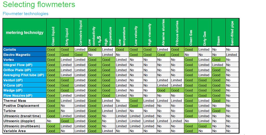
4 Flow Meter Technologies

5 Flow Meter Technologies (Magnetic) Electro-Magnetic (mag meters) The principle of the Magflow meter is based on Faraday's law of induction that states, that if a conductor is moved through a magnetic field, a voltage will be induced in it that is proportional to the velocity of the conductor.

6 Flow Meter Technologies (Magnetic) In the Electro-Magnetic flowmeter a magnetic field is produced across a cross-section of the pipe with the conductive liquid forming the conductor. Two sensing electrodes, set at right angles to the magnetic field, are used to detect the voltage that is generated across the flowing liquid and which is directly proportional to the flow rate of the media. U = c B D v Where: U = induced voltage (V) c = constant (meter factor) B = magnetic flux density (Wb/m²) D = diameter pipe (m) v = velocity of conductor (m/s) Electric-Magnetic flowmeters need a conductive liquid!!!
, free them from noise voltages and convert them to usable signals and indicate their values or provide them for further processing.")
7 Flow Meter Technologies (Magnetic) 1) Electro-Magnetic principle in relation to cabling and grounding The task of the transmitter is to amplify the relatively small measuring voltages (< 0.5mV), free them from noise voltages and convert them to usable signals and indicate their values or provide them for further processing. - Special attention needs to be taken on cabling, specific when separate mounted transmitters are used, see instruction manuals. Secondly, it is necessary to establish a fluid reference signal and therefor important that the potential of the liquid is grounded. 1. When the flowtube is mounted between unlined/uncoated metal pipes, the flange bolts provide the electrical connection from the flowtube to the pipeline and, therefore, the fluid. 2. When the flowtube is mounted between nonmetal or lined/coated metal pipe, installation of grounding rings on each pipe flange is required. Continuity is provided by connecting grounding wires from the flowtube to the grounding rings.

 incl.")
8 Flow Meter Technologies (Magnetic) General benefits The Electro-Magnetic flowmeter is regarded by many users as the universal answer to more than 90% of all flow metering applications. Some of the many benefits of Magflow meter are; Volumetric Flow measurement with linear output Low cost of ownership Economical purchase cost Easy installation Excellent durability and reliability No permanent pressure loss Very wide range-ability of flow measurement with proper sizing, typical better then 30:1. Unobstructed flow path and ideal for slurries Insensitive to flow profile changes (laminar to turbulent) incl. many non Newtonian liquids Short upstream / downstream piping (5D / 3D) Accuracy: up to ± 0.2% (0.5%) of actual flow over full range No recalibration requirements From very small (1.6mm / 1/16 ) to very big pipe diameters (2000mm/ 80 )
9 Flow Meter Technologies (Magnetic) Avoiding Problems The following guidelines will help prevent application and measurement problems with a Magflow meter and ensure premium performance: Liquid must be conductive!!! Improper configuration Improper sizing Insufficient upstream/downstream relaxation piping Improper meter orientation Partially full piping Correct cabling Accumulation of secondary phase ( gas, liquid or solid) inside the meter Other up-stream disturbances like bends, valves or pumps Low flows in general Presence of multiple phases.
10 Flow Meter Technologies (Mass - Coriolis) Coriolis Mass Flow Meter

11 Flow Meter Technologies (Mass - Coriolis) Why use Mass Flow Most chemical reactions are based largely on their mass relationship. Consequently, by measuring the Massflow of the product it is possible to control the process more accurately. Further, the components can be recorded and accounted for, in terms of Mass. Massflow is a primary unit of flow measurement and is unaffected by viscosity, density, conductivity, pressure and temperature. As a result it is inherently more accurate and meaningful for measuring material transfer. Traditionally, Massflow has been measured inferentially. Electromagnetic, orifice plate, turbine, ultrasonic, venturi, vortex etc. All measure the flow of the medium in terms of its velocity through the pipe and then combine this with temperature and density to Mass. However, such indirect methods commonly result in serious errors in measuring Massflow. Apart from Custody transfer applications, they are used in Chemical processes and expensive fluid handling

12 Flow Meter Technologies (Mass - Coriolis)
. He described an inertial force that acts on objects that are in motion relative to a rotating reference frame in 1835.")
13 Flow Meter Technologies (Mass - Coriolis) Theory of operation This type of flowmeter is based on the so-called Coriolis effect named after the French scientist and mathematician Gustave- Gaspard de Coriolis ( ). He described an inertial force that acts on objects that are in motion relative to a rotating reference frame in The Coriolis effect exists only when one uses a rotating reference frame. In the rotating frame it behaves exactly like a real force (that is to say, it causes acceleration and has real effects). However, the Coriolis force is a consequence of inertia and is not attributable to an identifiable originating body, as is the case for electromagnetic or nuclear forces, for example. From an analytical viewpoint, to use Newton's second law in a rotating system, the Coriolis force is mathematically necessary, but it disappears in a non-accelerating inertial frame of reference.
14 Flow Meter Technologies (Mass - Coriolis)
15 Flow Meter Technologies (Mass - Coriolis)
16 Flow Meter Technologies (Mass - Coriolis)
17 Flow Meter Technologies (Mass - Coriolis) 4 measurements are generally available as output on Coriolis flowmeters including the calculated volume. Mass flow (Phase shift ΔT) Density (resonance frequency) Temperature (Pt 100) Volume rate
18 Flow Meter Technologies (Mass - Coriolis)
19 Flow Meter Technologies (Mass - Coriolis)

20 Flow Meter Technologies (Mass - Coriolis)
21 Flow Meter Technologies (Mass - Coriolis) Avoiding Problems The following guidelines will help prevent application and measurement problems with a Coriolis Massflow meter and ensure premium performance: Improper configuration Improper sizing Insufficient upstream/downstream relaxation piping Improper meter orientation Correct mounting Correct cabling Accumulation of secondary phase ( gas, liquid or solid) inside the meter Other up-stream disturbances like bends, valves or pumps Low flows in general Presence of multiple phases (more then 2)


22 Flow Meter Technologies (Vortex) Vortex Flow Meter Basics Vortex shedding occurs naturally throughout nature and can be observed in a flag waving from a flagpole. The flagpole acts as a bluff body and vortex shedding occurs. As the wind speed increases the rate of vortex shedding increases and causes the flag to wave faster (higher frequency). Or when a plane takes off you can see the vortexes at the wing tips. Or like Leonardo de Vinci already did in the year 1510 under the duct of a bridge in the water.
 meets a non-streamlined obstacle called a bluff body.")
23 Flow Meter Technologies (Vortex) Vortex Flow Meter Theory of Operation Vortex meters are based on the phenomenon known as vortex shedding. This takes place when a turbulent media flow (liquid, gas or steam) meets a non-streamlined obstacle called a bluff body. Because the flow is unable to follow the defined contours of the obstacle, the peripheral layers of the fluid separate from its surfaces to form vortices in the low pressure area behind the body. These vortices are swept downstream to form a so-called Karman Vortex Street (Theodore von Kármán in 1911 described the stability criterion for the array of shed vortices). Vortices are shed alternately from either side of the bluff body at a frequency that, within a given Reynolds number range, is proportional to the mean flow velocity in the pipe. In vortex meters, the differential pressure changes that occur as the vortices are formed and shed, are used to actuate a sensor at a frequency proportional to the vortex shedding and the flow velocity.
 At higher velocities a low pressure region starts to form behind the bluff body (c) Beginning")

24 Flow Meter Technologies (Vortex) A natural phenomenon explained Formation of vortices: (a) Laminar flow region with fluid flowing evenly around the body (b) At higher velocities a low pressure region starts to form behind the bluff body (c) Beginning of turbulent flow region and formation of vortex. These usually undesirable vortexes are utilized as the basis for the measurement in vortex flowmeters. Every section between the vortexes represents a defined volume. Vortex is a true volumetric flow measurement.

25 Flow Meter Technologies (Vortex) Vortex Flow Meter Advantages True Volumetric Flow measurement % of Rate accuracy vs. % of Span, for better accuracy Low cost of ownership Economical purchase cost Easy installation Excellent durability and reliability Tolerant to wear compared to, for example Orifice plates and Turbine meters Permanent pressure loss is about 50% of an orifice plate Wide range of flow measurement with proper sizing 40:1 typical for Liquids 20:1 typical for Gas/Steam Few joints for fugitive emissions No moving parts, meaning virtually No maintenance costs Wide applicability, from liquid gas to superheated steam Page
26 Flow Meter Technologies (Vortex) Avoiding Problems The following guidelines will help prevent application and measurement problems with a Vortex meter and ensure premium performance: improper configuration improper sizing insufficient upstream/downstream relaxation piping improper meter orientation partially full piping accumulation of secondary phase ( gas, liquid or solid) inside the meter improper temperature/pressure taps down-stream Other up-stream disturbances like bends, valves or pumps flows below Reynolds numbers of flows below the Low Flow Cut-In (LFCI) process noise (at low flows or zero flow) presence of multiple phases.
.")
27 Flow Meter Technologies (Vortex) Installation Best Practices! Meter Location It is recommended that for liquid flows, the vortex meter be located a minimum of 5 PDs upstream of any valve (valve >5 PDs downstream of meter). It is recommended that for gas and steam flows, the vortex meter be located a minimum of 30 PDs downstream of any valve (valve >30 PDs upstream of meter). Pressure and Temperature Taps are used in Gas/ Steam applications. Pressure taps for mass or standard volumetric measurement should be located 3.5 to 4.5 PDs downstream of the meter. Temperature taps should be located 5 to 6 PDs downstream, and the smallest possible probe is recommended to reduce the chances of flow disturbance.
28 Flow Meter Technologies (Vortex) Liquid Installations Gas Installations Steam Installations
29 Flow Meter Technologies (Vortex) Installation Best Practices!

30 Flow Meter Technologies (Differential Press)
 is not constant, it must be known or measured.")
31 Flow Meter Technologies (dp) Basics; Pressure loss or Head loss The square root relationship between differential pressure (ΔP) and flow (Q) severely limits the turn-down ratio of such techniques to a maximum of 10:1 or less. If density (ρ ) is not constant, it must be known or measured. In practice the effect of density changes is not significant in the majority of liquid flow applications and needs only to be taken into account in the measurement of gas flows.
32 Flow Meter Technologies (dp)

33 Flow Meter Technologies (dp)
34 Flow Meter Technologies (dp)
35 Flow Meter Technologies (dp) Disadvantages; Permanent pressure head loss. Accuracy, method depending from 0.2% to 5%. Accuracy can be affected by fluctuations in the density, pressure and viscosity and by erosion and physical damage to the restriction. Often long straight pipe runs are required; for custody transfer applications, for example, with orifice plates the American Gas Association (AGA) requires 95 pipe diameters of straight pipe upstream of the measurement point. The output is not linearly related to flowrate, thus entailing square root extraction. There are a large number of potential leakage points. Advantages; Simple construction and Easy maintenance Relatively Low cost, specific on diameters >DN100, 4. Turndown ratio, typically from < 5:1 but used in combination with Multivariable Pressure transmitters turndown can extend to the turndown ratio of 10:1 and direct Massflow can be calculated. Suitable for high pressure and high temperatures No moving parts From history the most used flow measurement with many years of experience in the field.
36 Flow Meter Technologies (dp)
37 Flow Meter Technologies (dp)
38 Flow Meter Technologies (dp) Avoiding Problems The following guidelines will help prevent application and measurement problems with a dp flow meter and ensure premium performance: Improper configuration Improper sizing Insufficient upstream/downstream relaxation piping Improper meter orientation Correct mounting Correct cabling Accumulation of secondary phase ( gas, liquid or solid) inside the meter Other up-stream disturbances like bends, valves or pumps Low flows in general Presence of multiple phases (more then 2)
 5 basic parts Tube: glass,")

39 Flow Meter Technologies (Variable Area) 5 basic parts Tube: glass, metal, or plastic Float Scale Body or housing Fittings (customer connections)

40 Flow Meter Technologies (Variable Area) Tapered tube Float, free to move up and down Fluid flows up Float rises Space between float and wall varies Float finds equilibrium
41 Flow Meter Technologies (Variable Area) Benefits of Variable Area Cost-effective Repeatable Simple to install and maintain Variety of materials No power required Low pressure drop Downsides of Variable Area Resolution is relatively poor compared to other measurement principles Discoloration of tubes (Glass) Scales are built for a specific density and viscosity. Changes in temperature and pressure will affect accuracy.
42 Flow Meter Technologies (VA) Installation Best Practices!


43 Flow Meter Technologies (Turbine) A turbine spins on a rotor with an axis of symmetry that is parallel to the flow direction. The flow of media through the flow meter causes the turbine to rotate. As the turbine rotates, each blade of the turbine passes a sensor. The speed at which the turbine rotates is directly proportional to the volumetric flow as well as the rate at which the blades of the turbine pass the sensor.
44 Flow Meter Technologies (Turbine) Signal Sensors The sensor used to provide a signal can either be a magnet pick up, photoelectric cell or tachometer. A magnetic pick-up sensor is excited as each blade of the turbine passes, causing an alternating current (AC) to form. The frequency of the alternating current (AC) is proportional to the rate at which the blades of the turbine pass the sensor and ultimately the flow of media through the meter. A photoelectric cell also senses the motion of the turbine blades. Instead of indirectly measuring an implied current, the sensor produces electrical pulses as the blades pass the sensor. The pulses are counted or totalized over a time period to sense the rotational velocity of the turbine. A tachometer, like the photoelectric cell, also directly senses the presence of the turbine blades. A tachometer is most often an electromechanical device that produces electrical pulses as the blades pass the sensors and ultimately sense the rotational velocity of the turbine.
45 Flow Meter Technologies (Turbine) Designed for clean media (gases or liquids) with low kinematic viscosity. Ideal application is laminar flow of media through the media Mixed phase media, viscous drag, and turbulent flow patterns can all interfere with the dynamic behavior of the turbine, which is essential in providing accurate flow measurements. Avoiding issues with Turbine Meters Non-lubricating fluids can cause inaccuracies and premature wear on bearings. Consider grease fittings for non-lubricating fluids and gas service Accuracy issues at low flow rates due to the rotor/bearing drag. High flow velocities could cause premature bearing wear. Moving parts will degrade with time and use. Transitioning from gas to liquid: liquid to gas can mechanically stress the meter, degrade accuracy, and/or damage the meter. Typically seen when filling the meter in slug conditions. Not recommended for two phase flow such as steam flow metering.

46 Flow Meter Technologies (Ultrasonic) Uses a multiple slope transit time algorithm to provide accurate flow measurements.

47 Flow Meter Technologies (Turbine) Installation Best Practices! Typical manufacturer specifications for turbine meters call for straightpipe lengths of pipe diameters upstream and five diameters downstream. Additional straight-pipe recommendations include: 20 pipe diameters for 90-degree elbow, tee, filter, strainer, or thermowell; 25 pipe diameters for a partially open valve; and 50 pipe diameters for two elbows in different planes or if the flow is spiraling.
 as shown in the upper half of Fig. 1.")
48 Flow Meter Technologies (Ultrasonic) An ultrasonic beam of a given frequency is generated by applying a repetitive voltage pulse to the transducer crystals. This transmission goes first from the Downstream transducer to the Upstream transducer (red) as shown in the upper half of Fig. 1. The transmission is then made in the reverse direction, being sent from the Upstream transducer (red) to the Downstream transducer (blue) as shown in the lower half of Fig.1. The speed at which the ultrasound is transmitted through the liquid is accelerated slightly by the velocity of the liquid through the pipe. The subsequent time difference T1 T2 is directly proportional to the liquid flow velocity.
49 Flow Meter Technologies (Ultrasonic) Installing the U1000 Most consistent accurate results are achieved when the transducer guide rails are mounted at 45 with respect to the top of the pipe. Flow profile distortions can result from upstream disturbance such as bends, tees, valves, pumps and other similar obstructions. To ensure a uniform profile the transducers must be mounted far enough away from any cause of distortion such that it no longer has an effect. To obtain the most accurate results the condition of both the liquid and the pipe must be suitable to allow ultrasound transmission along the predetermined path. It is important that liquid flows uniformly within the length of pipe being monitored, and that the flow profile is not distorted by any upstream or downstream obstructions. This is best achieved by ensuring there is a straight length of pipe upstream of the transducers of at least 20 times the pipe diameter, and 10 times the pipe diameter on the downstream side, as shown in Figure 3. Flow Measurements can be made on shorter lengths of straight pipe, down to 10 diameters upstream and 5 diameters downstream, but when the transducers are mounted this close to any obstruction the resulting errors can be unpredictable.