TECHNIQUES OF INDUCTIVELY COUPLED PLASMA OPTICAL EMISSION SPECTROMETER S. KARTHIKEYAN SSA CENTRAL POLLUTION CONTROL BOARD SOUTH ZONE OFFICE BANGALORE
|
|
|
- Jacob Lloyd
- 5 years ago
- Views:
Transcription
1 TECHNIQUES OF INDUCTIVELY COUPLED PLASMA OPTICAL EMISSION SPECTROMETER By S. KARTHIKEYAN SSA CENTRAL POLLUTION CONTROL BOARD SOUTH ZONE OFFICE BANGALORE
2 INTRODUCTION ICP-OES is a sophisticated instrument used in determination of trace concentrations of elements in sample based on atomic spectrometry, after due pre treatment.
3 LAYOUT OF ICP-OES INSTRUMENT
4 INDUCTIVELY COUPLED PLASMA OPTICAL EMISSION SPECTROMETER INDUCTIVELY COUPLING: Process of transferring energy to a system through the use of electromotive forces generated by magnetic fields. PLASMA: A state of matter usually consisting of highly ionized gas that contains an appreciable fraction of equal numbers of ions and electrons in addition to neutral atoms and molecules.
5 INDUCTIVERLY COUPLED PLASMA (ICP) A high temperature discharge generated by flowing a conductive gas through a magnetic field induced by a load coil that surrounds the tubes carrying the gas. OPTICAL EMISSION SPECTROMETRY (OES) Elemental analysis technique that uses emission of electromagnetic radiation to detect the presence of the elements of interest.
6 PRINCIPLE A SAMPLE aerosol is generated in an appropriate nebulizer and spray chamber and is carried into the plasma through an injector tube located within the torch. Due to high temperature at Plasma region, the sample undergoes desolvation, vaporization, atomization, excitation and ionization. The Normal analytical zone is the region of the Plasma from which analyte emission is measured. From the wavelength, the element is identified. From the emission count, concentration of the analyte is determined.
7 PROCESS TAKES PLACE AT ICP DISCHARGE
8 COMPONENTS OF ICP 1. Sample introduction system A. Peristaltic pump B. Nebulizer C. Spray chambers D. Drains 2. Plasma - A. Demountable ICP torch B. RF Generators 3. Spectrometer A. Slit B. Collimator C. Gratings D. Prism E. Photo multiplier tube (PMT)
9 PERISTALTIC PUMP A pump in which the fluid is pushed through a length of flexible tubing by waves of mechanical contractions, usually caused by a series of rollers that travel along the length of the tubing. So, the flow is laminar without any pulse.
10 PERISTALTIC PUMP USED FOR ICP-OES
11 NEBULIZER A device used to create an aerosol from a liquid. A high speed stream of argon gas is directed perpendicular to the tip of a capillary tube. The solution is either drawn up through the capillary tube by the low pressure region created by the high speed gas or forced up the tube with a pump. In either case, contact between the high speed gas and the liquid stream causes the liquid to break up into an aerosol.
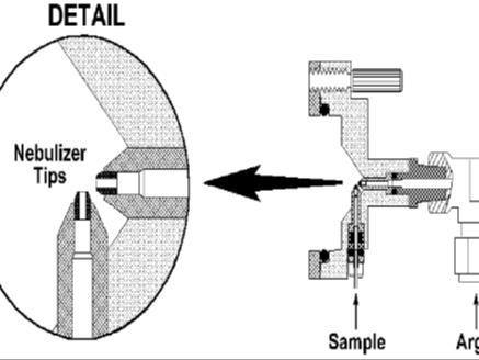
12 NEBULIZER
13 SPRAY CHAMBERS A device placed between a nebulizer and an atomization/excitation source, whose function is to separate the aerosol droplets according to their size and to smooth out fluctuations in the sample carrying gas flow. The primary function of spray chamber is to remove large droplets from the aerosol. A secondary purpose is to smooth out pulses that occur during nebulization, often due to pumping of the solution. For ICP operation, it is designed to allow droplets with dia of about 10 microns or smaller to pass on to the plasma.
14 SPRAY CHAMBER
15 DRAINS Drain carries excess sample from the spray chamber to a waste container can have an impact on the performance of ICP. It also provides the backpressure necessary to force the sample aerosol carrying nebulizer gas flow through the torch s injector tube and into the plasma discharge.
16 TORCHES The torch contains three concentric tubes. The spacing between the two outer tubes is kept narrow so that the gas introduced between them emerges at high velocity. This outside chamber is also designed to make the gas spiral tangentially around the chamber as it proceeds upward and acts as a coolant (PLASMA FLOW). The chamber between the outer flow and the inner flow sends gas directly under the plasma toroid. This flow is called (INTERMEDIATE FLOW) and prevents carbon formation on the tip of the injector tube.
17 PLASMA TORCH
18 NEBULIZER FLOW The gas flow that carries the sample aerosol is injected into the plasma through the central tube or injector. Due to small diameter at the end of the injector, the nebulizer flow can punch a hole through the plasma.
19 RADIO FREQUENCY GENERATORS The device that provides the power for the generation and sustainment of the plasma discharge. This power, typically ranging from about watts, is transferred to the plasma gas through a load coil surrounding the top of the torch.
20 DETECTORS Photo multiplier tube or PMT is a vacuum tube that contains a photosensitive material called the photocathode, that ejects electrons when it is struck by light. These electrons are accelerated towards a dynode which ejects two to five secondary electrons strike another dynode, ejecting more electrons which strike yet another dynode, causing a multiplicative effect along the way. Typical PMTs contain 9 to 16 stages. Collection of secondary electrons from the last dynode by the anode. The electrical current measured at the anode is then used as a relative measure of the intensity of the radiation reaching the PMT.
21 SOP OF ICP 1. All operational parameters should be set up in method file 2. All samples should be mentioned in sample file, with location number if auto sampler is used. 3. A result file should be created in order to store the test results in that.
22 APPLICATIONS 1. Environmentals and waters 2. Agricultural and Foods 3. Biological and clinical 4. Geological 5. Organics
23 THANK YOU